service schedule SUZUKI JIMNY 2005 3.G Service Workshop Manual
[x] Cancel search | Manufacturer: SUZUKI, Model Year: 2005, Model line: JIMNY, Model: SUZUKI JIMNY 2005 3.GPages: 687, PDF Size: 13.38 MB
Page 32 of 687

Downloaded from www.Manualslib.com manuals search engine MAINTENANCE AND LUBRICATION 0B-1
0A 6F1
0B
0B
6G
1A 6H
1B 6K
37A
3A 7A1
3B1 7B1
3C1 7C1
3D 7D
3E 7E
3F 7F
4A2 8A
4B 8B
8C
58D
5A 8E
5B
5C 9
5E
5E1 10
10A
610B
6-1
6A1
6A2
6A4
6B
6C
6E1
6E2
SECTION 0B
MAINTENANCE AND LUBRICATION
CONTENTS
Maintenance Schedule .................................. 0B-2
Maintenance Schedule Under Normal
Driving Conditions ........................................ 0B-2
Maintenance Recommended Under Severe
Driving Conditions ........................................ 0B-4
Maintenance Service...................................... 0B-5
Engine .......................................................... 0B-5
Drive Belt .................................................. 0B-5
Valve Lash................................................ 0B-6
Engine Oil and Filter ................................. 0B-6
Engine Coolant ......................................... 0B-8
Exhaust System ....................................... 0B-8
Ignition System ............................................. 0B-9
Spark Plugs .............................................. 0B-9
Fuel System ................................................. 0B-9
Air Cleaner Filter ...................................... 0B-9
Fuel Lines and Connections ................... 0B-10
Fuel Filter ............................................... 0B-10
Fuel Tank ............................................... 0B-10
Emission Control System ........................... 0B-10
Crankcase Ventilation Hoses and
Connections ........................................... 0B-10
PCV (Positive Crankcase Ventilation)
Valve ..................................................... 0B-11Fuel Evaporative Emission Control
System ................................................... 0B-11
Chassis and Body ...................................... 0B-11
Clutch ..................................................... 0B-11
Brake Discs and Pads ............................ 0B-11
Brake Drums and Shoes ........................ 0B-12
Brake Hoses and Pipes.......................... 0B-12
Brake Fluid ............................................. 0B-12
Parking Brake Lever and Cable ............. 0B-13
Tires/Wheels .......................................... 0B-13
Suspension System ............................... 0B-14
Propeller Shafts...................................... 0B-15
Manual Transmission Oil........................ 0B-16
Automatic Transmission Fluid ................ 0B-16
Transfer and Differential Oil ................... 0B-17
Steering System ..................................... 0B-18
Steering Knuckle Seal ............................ 0B-18
Power Steering (P/S) System
(if equipped) ........................................... 0B-19
All Hinges, Latches and Locks ............... 0B-19
Final Inspection............................................ 0B-20
Recommended Fluids and Lubricants ....... 0B-22
WARNING:
For vehicles equipped with Supplemental Restraint (Air Bag) System:
Service on and around the air bag system components or wiring must be performed only by an
authorized SUZUKI dealer. Refer to “Air Bag System Components and Wiring Location View” under
“General Description” in air bag system section in order to confirm whether you are performing ser-
vice on or near the air bag system components or wiring. Please observe all WARNINGS and “Ser-
vice Precautions” under “On-Vehicle Service” in air bag system section before performing service
on or around the air bag system components or wiring. Failure to follow WARNINGS could result in
unintentional activation of the system or could render the system inoperative. Either of these two
conditions may result in severe injury.
Technical service work must be started at least 90 seconds after the ignition switch is turned to the
“LOCK” position and the negative cable is disconnected from the battery. Otherwise, the system
may be activated by reserve energy in the Sensing and Diagnostic Module (SDM).
Page 33 of 687

Downloaded from www.Manualslib.com manuals search engine 0B-2 MAINTENANCE AND LUBRICATION
Maintenance Schedule
Maintenance Schedule Under Normal Driving Conditions
NOTE:
This interval should be judged by odometer reading or months, whichever comes first.
This table includes service as scheduled up to 90,000 km (54,000 miles) mileage. Beyond 90,000 km
(54,000 miles), carry out the same services at the same intervals respectively.
IntervalKm (x 1,000) 15 30 45 60 75 90
Miles (x 1,000) 9 1827364554
Months 12 24 36 48 60 72
ENGINE
Drive belt V-belt I R I R I R
V-rib belt (Flat type)––I––R
Valve lash (clearance) –I–I–I
Engine oil and oil filter R R R R R R
Engine coolant––R––R
Exhaust system–I–I–I
IGNITION SYSTEM
✱Spark plugs When
unleaded
fuel is usedVehicle without
HO2SNickel spark
plug–R–R–R
Iridium spark
plug––R––R
Vehicle with
HO2SNickel spark
plug––R––R
Iridium spark
plug–––R––
When leaded fuel is used, refer to “Maintenance Recommended Under Severe Driving Condi-
tions” in this section.
FUEL SYSTEM
Air cleaner filter I I R I I R
Fuel lines and connections–I–I–I
Fuel filter Replace every 210,000 km (126,000 miles).
Fuel tank––I––I
EMISSION CONTROL SYSTEM
Crankcase ventilation hoses and connections
(Vehicle without HO2S)––I––I
✱PCV valve Vehicle without HO2S––I––I
Vehicle with HO2S–––––I
✱Fuel evaporative emission
control systemVehicle without HO2S–I–I–I
Vehicle with HO2S–––––I
NOTE:
“R”: Replace or change
“I”: Inspect and correct, replace or lubricate if necessary
For Sweden, items with
✱
✱✱ ✱ (asterisk) should be performed by odometer reading only.
For spark plugs, replace every 50,000 km if the local law requires.
Nickel spark plug: BKR6E-11 (NGK) or K20PR-U11 (DENSO)
Iridium spark plug: IFR5E11 (NGK) or SK16PR-A11 (DENSO)
Page 620 of 687

Downloaded from www.Manualslib.com manuals search engine ENGINE AND EMISSION CONTROL SYSTEM 6E-15
On-Vehicle Service
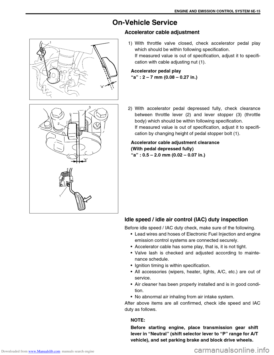
Accelerator cable adjustment
1) With throttle valve closed, check accelerator pedal play
which should be within following specification.
If measured value is out of specification, adjust it to specifi-
cation with cable adjusting nut (1).
Accelerator pedal play
“a” : 2 – 7 mm (0.08 – 0.27 in.)
2) With accelerator pedal depressed fully, check clearance
between throttle lever (2) and lever stopper (3) (throttle
body) which should be within following specification.
If measured value is out of specification, adjust it to specifi-
cation by changing height of pedal stopper bolt (1).
Accelerator cable adjustment clearance
(With pedal depressed fully)
“a” : 0.5 – 2.0 mm (0.02 – 0.07 in.)
Idle speed / idle air control (IAC) duty inspection
Before idle speed / IAC duty check, make sure of the following.
Lead wires and hoses of Electronic Fuel Injection and engine
emission control systems are connected securely.
Accelerator cable has some play, that is, it is not tight.
Valve lash is checked and adjusted according to mainte-
nance schedule.
Ignition timing is within specification.
All accessories (wipers, heater, lights, A/C, etc.) are out of
service.
Air cleaner has been properly installed and is in good condi-
tion.
No abnormal air inhaling from air intake system.
After above items are all confirmed, check idle speed and IAC
duty as follows.
NOTE:
Before starting engine, place transmission gear shift
lever in “Neutral” (shift selector lever to “P” range for A/T
vehicle), and set parking brake and block drive wheels.