steering wheel SUZUKI JIMNY 2005 3.G Service Workshop Manual
[x] Cancel search | Manufacturer: SUZUKI, Model Year: 2005, Model line: JIMNY, Model: SUZUKI JIMNY 2005 3.GPages: 687, PDF Size: 13.38 MB
Page 1 of 687

Downloaded from www.Manualslib.com manuals search engine IMPORTANT
WARNING/CAUTION/NOTE
Please read this manual and follow its instructions carefully. To emphasize special information, the words
WARNING, CAUTION
and NOTE
have special meanings. Pay special attention to the messages highlighted by
these signal words.
WARNING:
Indicates a potential hazard that could result in death or injury.
CAUTION:
Indicates a potential hazard that could result in vehicle damage.
NOTE:
Indicates special information to make maintenance easier or instructions clearer.
WARNING:
This service manual is intended for authorized Suzuki dealers and qualified service mechanics only.
Inexperienced mechanics or mechanics without the proper tools and equipment may not be able to
properly perform the services described in this manual.
Improper repair may result in injury to the mechanic and may render the vehicle unsafe for the driver
and passengers.
WARNING:
For vehicles equipped with a Supplemental Restraint or Air Bag System:
• Service on and around the air bag system components or wiring must be performed only by an
authorized SUZUKI dealer. Refer to “Air Bag System Components and Wiring Location View” under
“General Description” in air bag system section in order to confirm whether you are performing ser-
vice on or near the air bag system components or wiring. Please observe all WARNINGS and “Ser-
vice Precautions” under “On-Vehicle Service” in air bag system section before performing service
on or around the air bag system components or wiring. Failure to follow WARNINGS could result in
unintentional activation of the system or could render the system inoperative. Either of these two
conditions may result in severe injury.
If the air bag system and another vehicle system both need repair, Suzuki recommends that the air
bag system be repaired first, to help avoid unintended air bag system activation.
Do not modify the steering wheel, instrument panel or any other air bag system component on or
around air bag system components or wiring. Modifications can adversely affect air bag system
performance and lead to injury.
If the vehicle will be exposed to temperatures over 93°C (200°F), for example, during a paint baking
process, remove the air bag system components, that is air bag or inflator modules, SDM and/or
seat belt with pretensioner, beforehand to avoid component damage or unintended activation.
Page 4 of 687

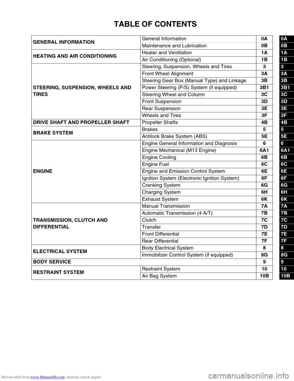
Downloaded from www.Manualslib.com manuals search engine TABLE OF CONTENTS
GENERAL INFORMATIONGeneral Information0A0A
Maintenance and Lubrication0B
0B
HEATING AND AIR CONDITIONINGHeater and Ventilation1A
1A
Air Conditioning (Optional)1B
1B
STEERING, SUSPENSION, WHEELS AND
TIRESSteering, Suspension, Wheels and Tires3
3
Front Wheel Alignment3A
3A
Steering Gear Box (Manual Type) and Linkage3B
3B
Power Steering (P/S) System (if equipped)3B1
3B1
Steering Wheel and Column3C
3C
Front Suspension3D
3D
Rear Suspension3E
3E
Wheels and Tires3F
3F
DRIVE SHAFT AND PROPELLER SHAFT
Propeller Shafts4B
4B
BRAKE SYSTEMBrakes5
5
Antilock Brake System (ABS)5E
5E
ENGINEEngine General Information and Diagnosis6
6
Engine Mechanical (M13 Engine)6A1
6A1
Engine Cooling6B
6B
Engine Fuel6C
6C
Engine and Emission Control System6E
6E
Ignition System (Electronic Ignition System)6F
6F
Cranking System6G
6G
Charging System6H
6H
Exhaust System6K
6K
TRANSMISSION, CLUTCH AND
DIFFERENTIALManual Transmission7A
7A
Automatic Transmission (4 A/T)7B
7B
Clutch7C
7C
Transfer7D
7D
Front Differential7E
7E
Rear Differential7F
7F
ELECTRICAL SYSTEMBody Electrical System8
8
Immobilizer Control System (if equipped)8G
8G
BODY SERVICE9
9
RESTRAINT SYSTEMRestraint System10
10
Air Bag System10B
10B
Page 8 of 687

Downloaded from www.Manualslib.com manuals search engine GENERAL INFORMATION 0A-3
Precautions
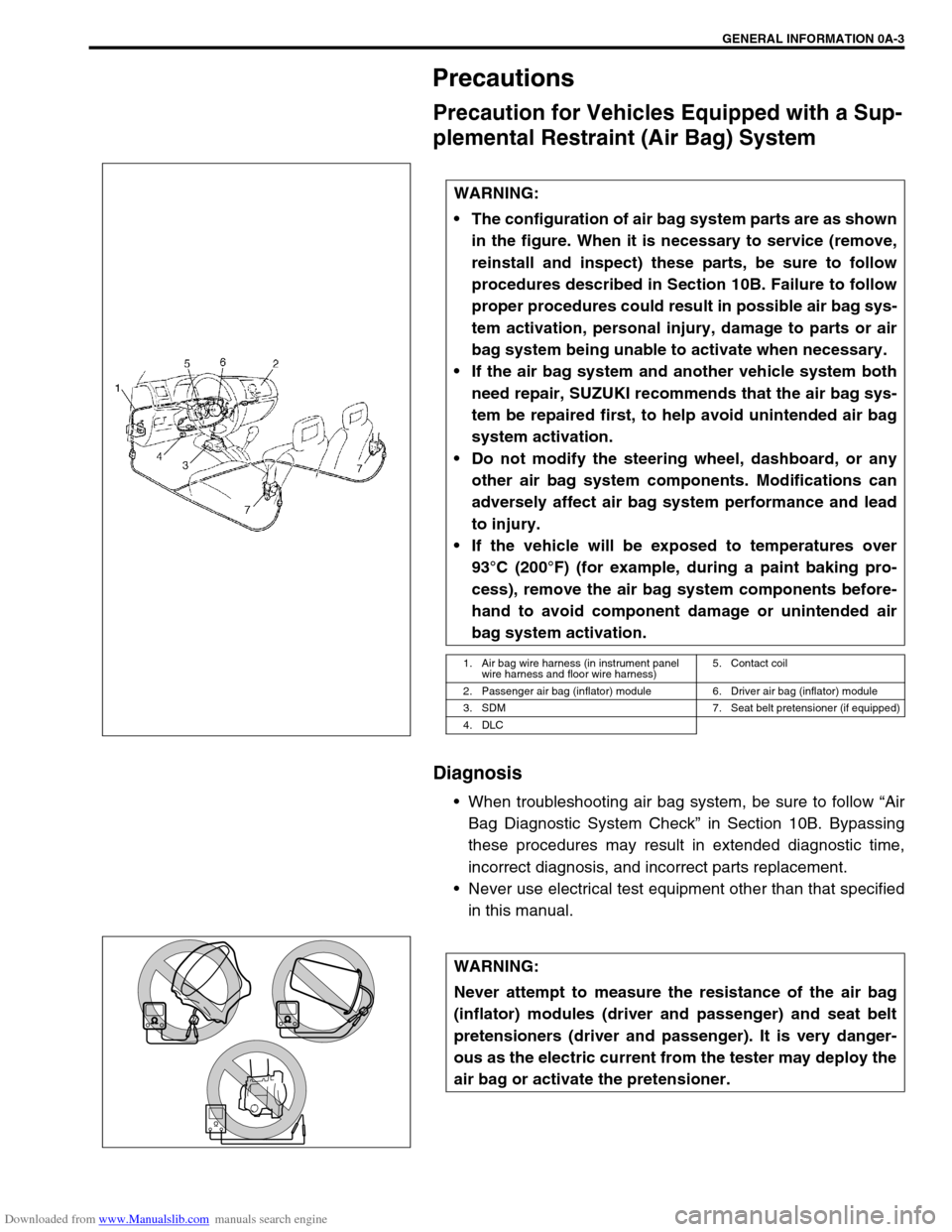
Precaution for Vehicles Equipped with a Sup-
plemental Restraint (Air Bag) System
Diagnosis
When troubleshooting air bag system, be sure to follow “Air
Bag Diagnostic System Check” in Section 10B. Bypassing
these procedures may result in extended diagnostic time,
incorrect diagnosis, and incorrect parts replacement.
Never use electrical test equipment other than that specified
in this manual. WARNING:
The configuration of air bag system parts are as shown
in the figure. When it is necessary to service (remove,
reinstall and inspect) these parts, be sure to follow
procedures described in Section 10B. Failure to follow
proper procedures could result in possible air bag sys-
tem activation, personal injury, damage to parts or air
bag system being unable to activate when necessary.
If the air bag system and another vehicle system both
need repair, SUZUKI recommends that the air bag sys-
tem be repaired first, to help avoid unintended air bag
system activation.
Do not modify the steering wheel, dashboard, or any
other air bag system components. Modifications can
adversely affect air bag system performance and lead
to injury.
If the vehicle will be exposed to temperatures over
93°C (200°F) (for example, during a paint baking pro-
cess), remove the air bag system components before-
hand to avoid component damage or unintended air
bag system activation.
1. Air bag wire harness (in instrument panel
wire harness and floor wire harness)5. Contact coil
2. Passenger air bag (inflator) module 6. Driver air bag (inflator) module
3. SDM 7. Seat belt pretensioner (if equipped)
4. DLC
WARNING:
Never attempt to measure the resistance of the air bag
(inflator) modules (driver and passenger) and seat belt
pretensioners (driver and passenger). It is very danger-
ous as the electric current from the tester may deploy the
air bag or activate the pretensioner.
Page 26 of 687

Downloaded from www.Manualslib.com manuals search engine GENERAL INFORMATION 0A-21
Abbreviations May Be Used In This Manual
Abbreviations
AABC
ATDC
API
ATF
ALR
AC
A/T
A/C
ABDC
A/F
A-ELRAnti-lock Brake System
After Top Dead Center
American Petroleum Institute
Automatic Transmission Fluid
Automatic Locking Retractor
Alternating Current
Automatic Transmission
Air Conditioning
After Bottom Dead Center
Air Fuel Mixture Ratio
Automatic-Emergency
Locking RetractorEEBCM
ECM
ECT Sensor
EGR
EGRT Sensor
EFE Heater
ELR
EPS
EVAP
EVAP CanisterElectronic Brake Control Module,
ABS Control Module
Engine Control Module
Engine Coolant Temperature
Sensor (Water Temp. Sensor,
WTS)
Exhaust Gas Recirculation
EGR Temperature Sensor
(Recirculated Exhaust Gas Temp.
Sensor, REGTS)
Early Fuel Evaporation
Heater (Positive Temperature
Coefficient, PTC Heater)
Emergency Locking Retractor
Electronic Power Steering
Evaporative Emission
Evaporative Emission Canister
(Charcoal Canister) BB+
BTDC
BBDCBattery Positive Voltage
Before Top Dead Center
Before Bottom Dead Center
CCKT
CMP Sensor
CO
CPP Switch
CPU
CRSCircuit
Camshaft Position Sensor
(Crank Angle Sensor, CAS)
Carbon Monoxide
Clutch Pedal Position Switch
(Clutch Switch, Clutch Start
Switch)
Central Processing Unit
Child Restraint SystemF 4WD 4 Wheel Drive
GGEN
GNDGenerator
Ground
HHC
HO2SHydrocarbons
Heated Oxygen Sensor
DDC
DLC
DOHC
DOJ
DRL
DTCDirect Current
Data Link Connector
(Assembly Line Diag. Link, ALDL,
Serial Data Link, SDL)
Double Over Head Camshaft
Double Offset Joint
Daytime Running Light
Diagnostic Trouble Code
(Diagnostic Code)IIAC Valve
IAT Sensor
ICM
IG
ISC ActuatorIdle Air Control Valve (Idle Speed
Control Solenoid Valve, ISC
Solenoid Valve)
Intake Air Temperature Sensor
(Air temperature Sensor, ATS)
Immobilizer Control Module
Ignition
Idle Speed Control Actuator
(Motor)
Page 27 of 687

Downloaded from www.Manualslib.com manuals search engine 0A-22 GENERAL INFORMATION
LLH
LSPVLeft Hand
Load Sensing Proportioning Valve
TTBI
TCC
TCM
TP Sensor
TVV
TWC
2WDThrottle Body Fuel Injection
(Single-Point Fuel Injection, SPI)
Torque Converter Clutch
Transmission Control Module
(A/T Controller, A/T Control Mod-
ule)
Throttle Position Sensor
Thermal Vacuum Valve
(Thermal Vacuum Switching Valve,
TVSV, Bimetal Vacuum Switching
Valve, BVSV)
Three Way Catalytic Converter
(Three Way Catalyst)
2 Wheel Drive MMAF Sensor
MAP Sensor
Max
MFI
Min
MIL
M/TMass Air Flow Sensor
(Air Flow Sensor, AFS, Air Flow
Meter, AFM)
Manifold Absolute Pressure
Sensor (Pressure Sensor, PS)
Maximum
Multiport Fuel Injection
(Multipoint Fuel Injection)
Minimum
Malfunction Indicator Lamp
(“CHECK ENGINE” Light)
Manual Transmission
N NOx Nitrogen Oxides VVIN
VSSVehicle Identification Number
Vehicle Speed Sensor
OOBD
O/D
OHCOn-Board Diagnostic System
(Self-Diagnosis Function)
Overdrive
Over Head CamshaftWWU-OC
WU-TWCWarm Up Oxidation Catalytic
Converter
Warm Up Three Way Catalytic
Converter
PPNP
P/S
PSP Switch
PCM
PCVPark/Neutral Position
Power Steering
Power Steering Pressure Switch
(P/S Pressure Switch)
Powertrain Control Module
Positive Crankcase Ventilation
R RH Right Hand
SSAE
SDM
SFI
SOHCSociety of Automotive Engineers
Sensing and Diagnostic Module
(Air bag controller, Air bag control
module)
Sequential Multiport Fuel Injection
Single Over Head Camshaft
Page 32 of 687

Downloaded from www.Manualslib.com manuals search engine MAINTENANCE AND LUBRICATION 0B-1
0A 6F1
0B
0B
6G
1A 6H
1B 6K
37A
3A 7A1
3B1 7B1
3C1 7C1
3D 7D
3E 7E
3F 7F
4A2 8A
4B 8B
8C
58D
5A 8E
5B
5C 9
5E
5E1 10
10A
610B
6-1
6A1
6A2
6A4
6B
6C
6E1
6E2
SECTION 0B
MAINTENANCE AND LUBRICATION
CONTENTS
Maintenance Schedule .................................. 0B-2
Maintenance Schedule Under Normal
Driving Conditions ........................................ 0B-2
Maintenance Recommended Under Severe
Driving Conditions ........................................ 0B-4
Maintenance Service...................................... 0B-5
Engine .......................................................... 0B-5
Drive Belt .................................................. 0B-5
Valve Lash................................................ 0B-6
Engine Oil and Filter ................................. 0B-6
Engine Coolant ......................................... 0B-8
Exhaust System ....................................... 0B-8
Ignition System ............................................. 0B-9
Spark Plugs .............................................. 0B-9
Fuel System ................................................. 0B-9
Air Cleaner Filter ...................................... 0B-9
Fuel Lines and Connections ................... 0B-10
Fuel Filter ............................................... 0B-10
Fuel Tank ............................................... 0B-10
Emission Control System ........................... 0B-10
Crankcase Ventilation Hoses and
Connections ........................................... 0B-10
PCV (Positive Crankcase Ventilation)
Valve ..................................................... 0B-11Fuel Evaporative Emission Control
System ................................................... 0B-11
Chassis and Body ...................................... 0B-11
Clutch ..................................................... 0B-11
Brake Discs and Pads ............................ 0B-11
Brake Drums and Shoes ........................ 0B-12
Brake Hoses and Pipes.......................... 0B-12
Brake Fluid ............................................. 0B-12
Parking Brake Lever and Cable ............. 0B-13
Tires/Wheels .......................................... 0B-13
Suspension System ............................... 0B-14
Propeller Shafts...................................... 0B-15
Manual Transmission Oil........................ 0B-16
Automatic Transmission Fluid ................ 0B-16
Transfer and Differential Oil ................... 0B-17
Steering System ..................................... 0B-18
Steering Knuckle Seal ............................ 0B-18
Power Steering (P/S) System
(if equipped) ........................................... 0B-19
All Hinges, Latches and Locks ............... 0B-19
Final Inspection............................................ 0B-20
Recommended Fluids and Lubricants ....... 0B-22
WARNING:
For vehicles equipped with Supplemental Restraint (Air Bag) System:
Service on and around the air bag system components or wiring must be performed only by an
authorized SUZUKI dealer. Refer to “Air Bag System Components and Wiring Location View” under
“General Description” in air bag system section in order to confirm whether you are performing ser-
vice on or near the air bag system components or wiring. Please observe all WARNINGS and “Ser-
vice Precautions” under “On-Vehicle Service” in air bag system section before performing service
on or around the air bag system components or wiring. Failure to follow WARNINGS could result in
unintentional activation of the system or could render the system inoperative. Either of these two
conditions may result in severe injury.
Technical service work must be started at least 90 seconds after the ignition switch is turned to the
“LOCK” position and the negative cable is disconnected from the battery. Otherwise, the system
may be activated by reserve energy in the Sensing and Diagnostic Module (SDM).
Page 34 of 687

Downloaded from www.Manualslib.com manuals search engine MAINTENANCE AND LUBRICATION 0B-3
IntervalKm (x 1,000) 153045607590
Miles (x 1,000) 9 18 27 36 45 54
Months 12 24 36 48 60 72
CHASSIS AND BODY
Clutch (pedal height and travel)–I–I–I
Brake discs and pads (thickness, wear, damage) I I I I I I
Brake drums and shoes (wear, damage)–I–I–I
Brake hoses and pipes (leakage, damage, clamp)–I–I–I
Brake fluid–R–R–R
Brake lever and cable (damage, stroke, operation) Inspect at first 15,000 km (9,000 miles) only.
Tires (wear, damage, rotation) I I I I I I
Wheel discs (damage) I I I I I I
Suspension system (tightness, damage, rattle, breakage)–I–I–I
Propeller shafts––I––I
Manual transmission oil (leakage, level) (I: 1st 15,000 km only) I–R––R
Automatic transmission Fluid level–I–I–I
Fluid change Replace every 165,000 km (99,000 miles).
Fluid hose–––R––
Transfer oil (leakage, level) I–I–I–
Differential oil (leakage, level) (R: 1st 15,000 km only) R or I–I–I–
Steering system (tightness, damage, breakage, rattle)–I–I–I
Power steering (if equipped) I I I I I I
All latches, hinges and locks–I–I–I
NOTE:
“R”: Replace or change
“I”: Inspect and correct, replace or lubricate if necessary
Page 35 of 687

Downloaded from www.Manualslib.com manuals search engine 0B-4 MAINTENANCE AND LUBRICATION
Maintenance Recommended Under Severe Driving Conditions
If the vehicle is usually used under the conditions corresponding to any severe condition code given below, it is
recommended that applicable maintenance operation be performed at the particular interval as shown in the fol-
lowing table.
Severe condition code
A : Repeated short trips
B : Driving on rough and/or muddy roads
C : Driving on dusty roads
D : Driving in extremely cold weather and/or salted roads
E : Repeated short trips in extremely cold weather
F : Leaded fuel use
G : – – – – –
H : Trailer towing (if admitted)
Severe
Condition CodeMaintenanceMaintenance
OperationMaintenance Interval
– B C D – – – –Drive belt (V-rib belt)IEvery 15,000 km
(9,000 miles) or 12 months
REvery 45,000 km
(27,000 miles) or 36 months
A – C D E F – H Engine oil and oil filter R Every 5,000 km (3,000 miles) or 4 months
– B – – – – – –Exhaust pipe mountings IEvery 15,000 km
(9,000 miles) or 12 months
– – C – – – – –Air cleaner filter ✱1I Every 2,500 km (1,500 miles)
REvery 30,000 km
(18,000 miles) or 24 months
A B C – E F – H Spark plugsNickel spark plug R Every 10,000 km (6,000 miles) or 8 months
Iridium spark plug
REvery 30,000 km
(18,000 miles) or 24 months
– B C D – – – H Wheel bearing IEvery 15,000 km
(9,000 miles) or 12 months
– B – – – – – –Suspension bolts and nuts TEvery 15,000 km
(9,000 miles) or 12 months
– B – D E – – H Propeller shafts IEvery 15,000 km
(9,000 miles) or 12 months
– B – – E – – HManual transmission,
transfer and differential oilRFirst time only:
15,000 km (9,000 miles) or 12 months
Second time and after: Every 30,000 km
(18,000 miles) or 24 months reckoning from
0 km (0 mile) or 0 month
– B – – E – – H Automatic transmission fluid REvery 30,000 km
(18,000 miles) or 24 months
– B C D – – – –Steering knuckle seal IEvery 15,000 km
(9,000 miles) or 12 months
NOTE:
“I”: Inspect and correct, replace or lubricate if necessary
“R”: Replace or change
“T”: Tighten to the specified torque
✱
✱✱ ✱1: Inspect or replace more frequently if necessary
Page 49 of 687

Downloaded from www.Manualslib.com manuals search engine 0B-18 MAINTENANCE AND LUBRICATION
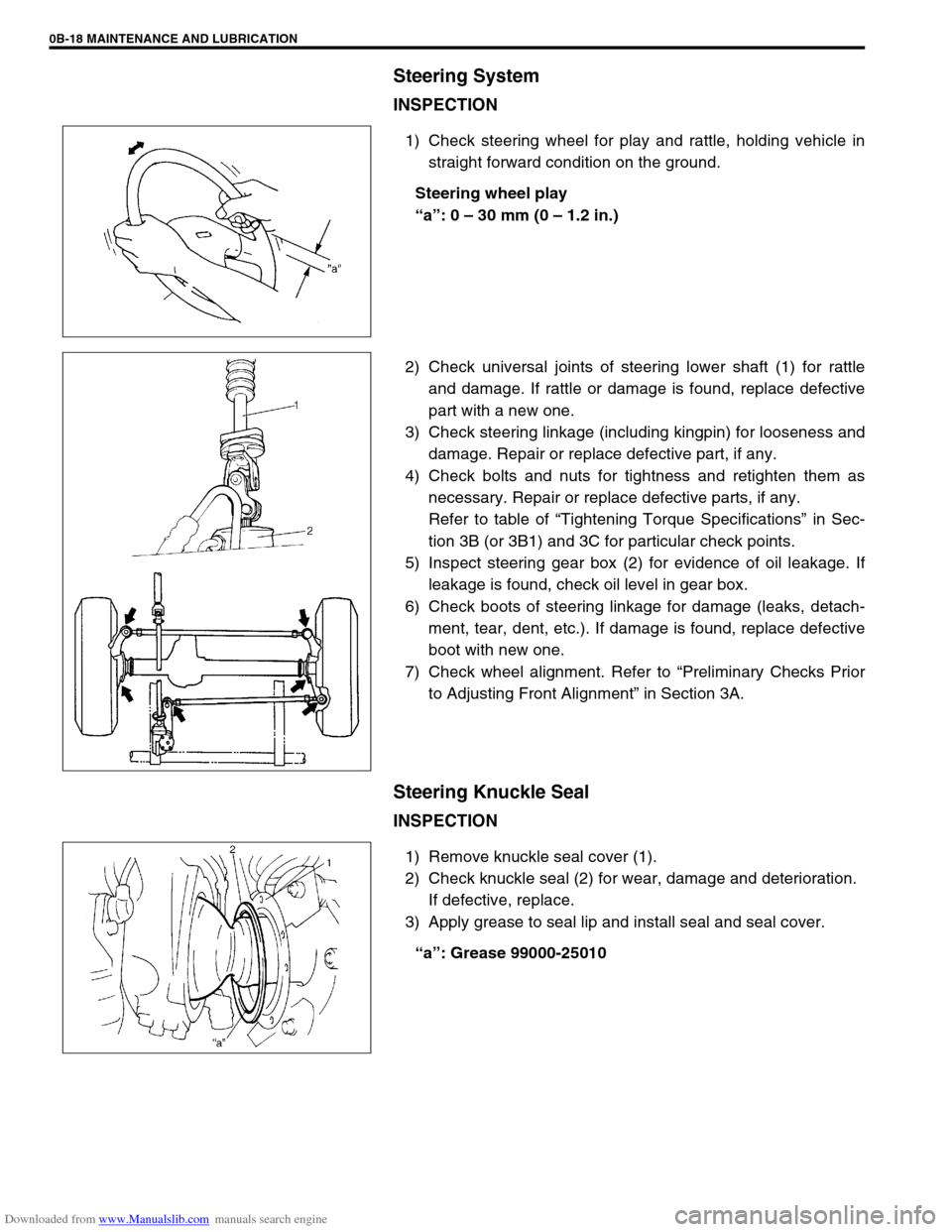
Steering System
INSPECTION
1) Check steering wheel for play and rattle, holding vehicle in
straight forward condition on the ground.
Steering wheel play
“a”: 0 – 30 mm (0 – 1.2 in.)
2) Check universal joints of steering lower shaft (1) for rattle
and damage. If rattle or damage is found, replace defective
part with a new one.
3) Check steering linkage (including kingpin) for looseness and
damage. Repair or replace defective part, if any.
4) Check bolts and nuts for tightness and retighten them as
necessary. Repair or replace defective parts, if any.
Refer to table of “Tightening Torque Specifications” in Sec-
tion 3B (or 3B1) and 3C for particular check points.
5) Inspect steering gear box (2) for evidence of oil leakage. If
leakage is found, check oil level in gear box.
6) Check boots of steering linkage for damage (leaks, detach-
ment, tear, dent, etc.). If damage is found, replace defective
boot with new one.
7) Check wheel alignment. Refer to “Preliminary Checks Prior
to Adjusting Front Alignment” in Section 3A.
Steering Knuckle Seal
INSPECTION
1) Remove knuckle seal cover (1).
2) Check knuckle seal (2) for wear, damage and deterioration.
If defective, replace.
3) Apply grease to seal lip and install seal and seal cover.
“a”: Grease 99000-25010
Page 52 of 687

Downloaded from www.Manualslib.com manuals search engine MAINTENANCE AND LUBRICATION 0B-21
GEARSHIFT OR SELECTOR LEVER (TRANSMISSION)
Check gear shift or selector lever for smooth shifting to all positions and for good performance of transmission in
any position.
With automatic transmission equipped vehicle, also check that shift indicator indicates properly according to
which position selector lever is shifted to.
With automatic transmission equipped vehicle, make sure that vehicle is at complete stop when shifting selector
lever to “P” range position and release all brakes.
BRAKE
Foot Brake
Check the following:
that brake pedal has proper travel,
that brake works properly,
that it is free from noise,
that braking force is applied equally on all wheels,
and that brake do not drag.
Parking Brake
Check that lever has proper travel.
Check to ensure that parking brake is fully effective when the vehicle is stopped on the safe slope and brake
lever is pulled all the way.
STEERING
Check to ensure that steering wheel is free from instability, or abnormally heavy feeling.
Check that the vehicle does not wander or pull to one side.
ENGINE
Check that engine responds readily at all speeds.
Check that engine is free from abnormal noise and abnormal vibration.
BODY, WHEELS AND POWER TRANSMITTING SYSTEM
Check that body, wheels and power transmitting system are free from abnormal noise and abnormal vibration or
any other abnormal condition.
METERS AND GAUGE
Check that speedometer, odometer, fuel meter, temperature gauge, etc. are operating accurately.
LIGHTS
Check that all lights operate properly.
WINDSHIELD DEFROSTER
Periodically check that air comes out from defroster outlet when operating heater or air conditioning.
Set mode control lever to defroster position and fan switch lever to “HI” position for this check. WARNING:
With vehicle parked on a fairly steep slope, make sure nothing is in the way downhill to avoid any per-
sonal injury or property damage. Be prepared to apply regular brake quickly even if vehicle should
start to move.