warning lights SUZUKI JIMNY 2005 3.G Service Workshop Manual
[x] Cancel search | Manufacturer: SUZUKI, Model Year: 2005, Model line: JIMNY, Model: SUZUKI JIMNY 2005 3.GPages: 687, PDF Size: 13.38 MB
Page 52 of 687

Downloaded from www.Manualslib.com manuals search engine MAINTENANCE AND LUBRICATION 0B-21
GEARSHIFT OR SELECTOR LEVER (TRANSMISSION)
Check gear shift or selector lever for smooth shifting to all positions and for good performance of transmission in
any position.
With automatic transmission equipped vehicle, also check that shift indicator indicates properly according to
which position selector lever is shifted to.
With automatic transmission equipped vehicle, make sure that vehicle is at complete stop when shifting selector
lever to “P” range position and release all brakes.
BRAKE
Foot Brake
Check the following:
that brake pedal has proper travel,
that brake works properly,
that it is free from noise,
that braking force is applied equally on all wheels,
and that brake do not drag.
Parking Brake
Check that lever has proper travel.
Check to ensure that parking brake is fully effective when the vehicle is stopped on the safe slope and brake
lever is pulled all the way.
STEERING
Check to ensure that steering wheel is free from instability, or abnormally heavy feeling.
Check that the vehicle does not wander or pull to one side.
ENGINE
Check that engine responds readily at all speeds.
Check that engine is free from abnormal noise and abnormal vibration.
BODY, WHEELS AND POWER TRANSMITTING SYSTEM
Check that body, wheels and power transmitting system are free from abnormal noise and abnormal vibration or
any other abnormal condition.
METERS AND GAUGE
Check that speedometer, odometer, fuel meter, temperature gauge, etc. are operating accurately.
LIGHTS
Check that all lights operate properly.
WINDSHIELD DEFROSTER
Periodically check that air comes out from defroster outlet when operating heater or air conditioning.
Set mode control lever to defroster position and fan switch lever to “HI” position for this check. WARNING:
With vehicle parked on a fairly steep slope, make sure nothing is in the way downhill to avoid any per-
sonal injury or property damage. Be prepared to apply regular brake quickly even if vehicle should
start to move.
Page 272 of 687

Downloaded from www.Manualslib.com manuals search engine BRAKES 5-11
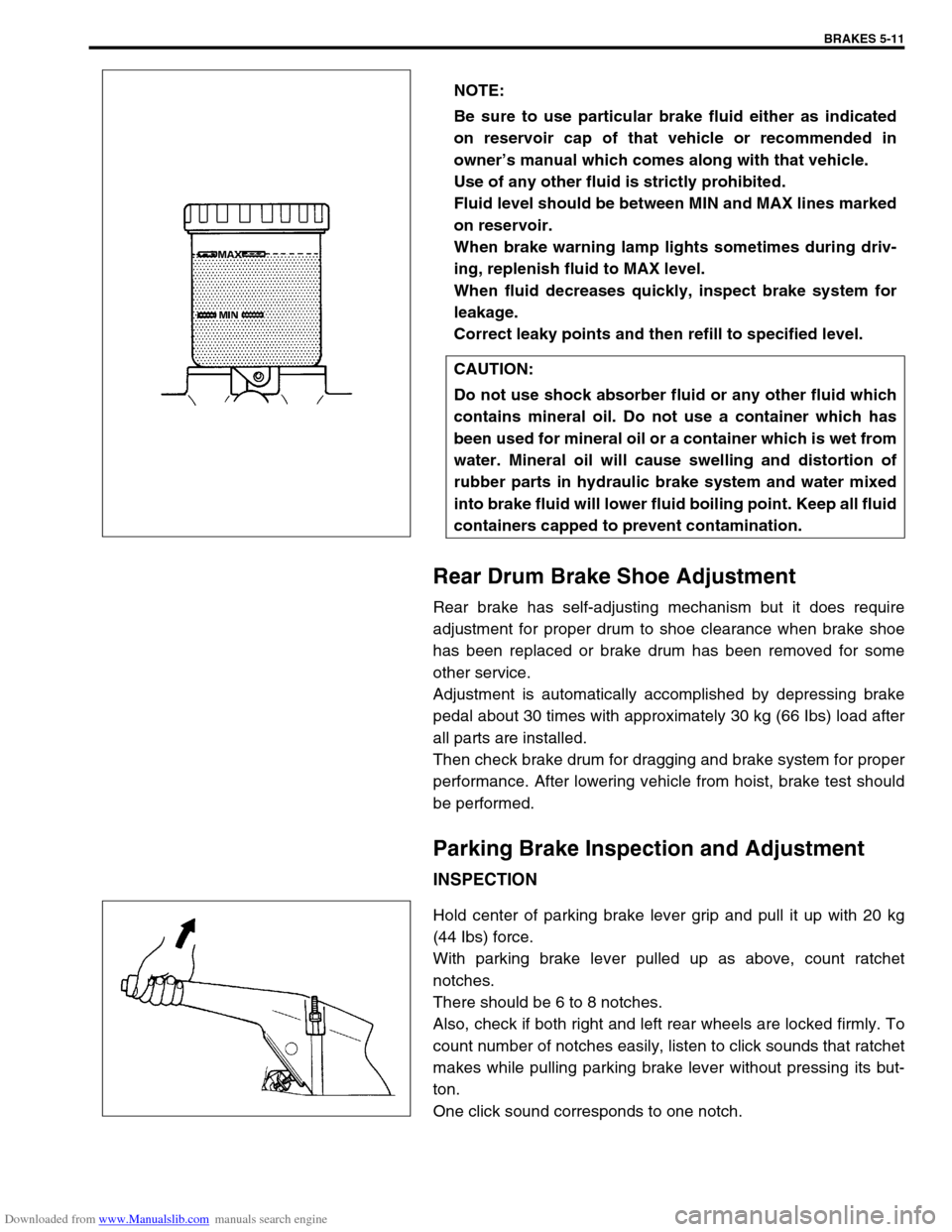
Rear Drum Brake Shoe Adjustment
Rear brake has self-adjusting mechanism but it does require
adjustment for proper drum to shoe clearance when brake shoe
has been replaced or brake drum has been removed for some
other service.
Adjustment is automatically accomplished by depressing brake
pedal about 30 times with approximately 30 kg (66 Ibs) load after
all parts are installed.
Then check brake drum for dragging and brake system for proper
performance. After lowering vehicle from hoist, brake test should
be performed.
Parking Brake Inspection and Adjustment
INSPECTION
Hold center of parking brake lever grip and pull it up with 20 kg
(44 Ibs) force.
With parking brake lever pulled up as above, count ratchet
notches.
There should be 6 to 8 notches.
Also, check if both right and left rear wheels are locked firmly. To
count number of notches easily, listen to click sounds that ratchet
makes while pulling parking brake lever without pressing its but-
ton.
One click sound corresponds to one notch.NOTE:
Be sure to use particular brake fluid either as indicated
on reservoir cap of that vehicle or recommended in
owner’s manual which comes along with that vehicle.
Use of any other fluid is strictly prohibited.
Fluid level should be between MIN and MAX lines marked
on reservoir.
When brake warning lamp lights sometimes during driv-
ing, replenish fluid to MAX level.
When fluid decreases quickly, inspect brake system for
leakage.
Correct leaky points and then refill to specified level.
CAUTION:
Do not use shock absorber fluid or any other fluid which
contains mineral oil. Do not use a container which has
been used for mineral oil or a container which is wet from
water. Mineral oil will cause swelling and distortion of
rubber parts in hydraulic brake system and water mixed
into brake fluid will lower fluid boiling point. Keep all fluid
containers capped to prevent contamination.
Page 319 of 687

Downloaded from www.Manualslib.com manuals search engine 5E-2 ANTILOCK BRAKE SYSTEM (ABS)
General Description
The ABS (Antilock Brake System) is a system to prevent each wheel to lock during hard braking or braking on a
slippery road by controlling the fluid pressure from master cylinder to each brake (either brake caliper or wheel
cylinder).
The ABS of this vehicle monitors all four wheels (four sensors) and controls all four wheels when the system is
active.
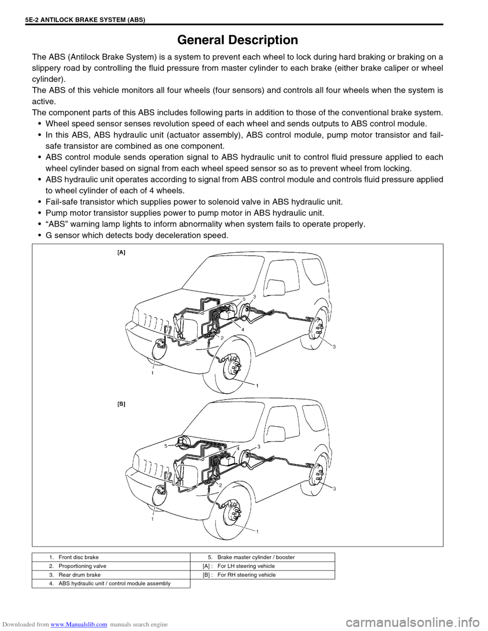
The component parts of this ABS includes following parts in addition to those of the conventional brake system.
Wheel speed sensor senses revolution speed of each wheel and sends outputs to ABS control module.
In this ABS, ABS hydraulic unit (actuator assembly), ABS control module, pump motor transistor and fail-
safe transistor are combined as one component.
ABS control module sends operation signal to ABS hydraulic unit to control fluid pressure applied to each
wheel cylinder based on signal from each wheel speed sensor so as to prevent wheel from locking.
ABS hydraulic unit operates according to signal from ABS control module and controls fluid pressure applied
to wheel cylinder of each of 4 wheels.
Fail-safe transistor which supplies power to solenoid valve in ABS hydraulic unit.
Pump motor transistor supplies power to pump motor in ABS hydraulic unit.
“ABS” warning lamp lights to inform abnormality when system fails to operate properly.
G sensor which detects body deceleration speed.
1. Front disc brake 5. Brake master cylinder / booster
2. Proportioning valve [A] : For LH steering vehicle
3. Rear drum brake [B] : For RH steering vehicle
4. ABS hydraulic unit / control module assembly
Page 322 of 687

Downloaded from www.Manualslib.com manuals search engine ANTILOCK BRAKE SYSTEM (ABS) 5E-5
ABS Control Module
Self-diagnosis function
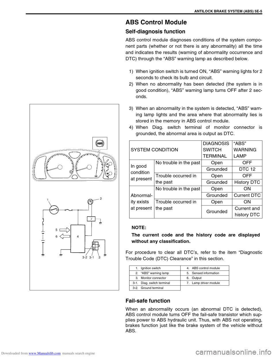
ABS control module diagnoses conditions of the system compo-
nent parts (whether or not there is any abnormality) all the time
and indicates the results (warning of abnormality occurrence and
DTC) through the “ABS” warning lamp as described below.
1) When ignition switch is turned ON, “ABS” warning lights for 2
seconds to check its bulb and circuit.
2) When no abnormality has been detected (the system is in
good condition), “ABS” warning lamp turns OFF after 2 sec-
onds.
3) When an abnormality in the system is detected, “ABS” warn-
ing lamp lights and the area where that abnormality lies is
stored in the memory in ABS control module.
4) When Diag. switch terminal of monitor connector is
grounded, the abnormal area is output as DTC.
For procedure to clear all DTC’s, refer to the item “Diagnostic
Trouble Code (DTC) Clearance” in this section.
Fail-safe function
When an abnormality occurs (an abnormal DTC is detected),
ABS control module turns OFF the fail-safe transistor which sup-
plies power to ABS hydraulic unit. Thus, with ABS not operating,
brakes function just like the brake system of the vehicle without
ABS.SYSTEM CONDITIONDIAGNOSIS
SWITCH
TERMINAL“ABS”
WARNING
LAMP
In good
condition
at presentNo trouble in the past Open OFF
Grounded DTC 12
Trouble occurred in
the pastOpen OFF
Grounded History DTC
Abnormal-
ity exists
at presentNo trouble in the past Open ON
Grounded Current DTC
Trouble occurred in
the pastOpen ON
GroundedCurrent and
history DTC
NOTE:
The current code and the history code are displayed
without any classification.
1. Ignition switch 4. ABS control module
2.“ABS” warning lamp 5. Sensed information
3. Monitor connector 6. Output
3-1. Diag. switch terminal 7. Lamp driver module
3-2. Ground terminal
Page 400 of 687

Downloaded from www.Manualslib.com manuals search engine ENGINE GENERAL INFORMATION AND DIAGNOSIS 6-43
Table A-1 Malfunction Indicator Lamp Circuit Check - Lamp Does Not Come
“ON” at Ignition Switch ON (But Engine at Stop)
CIRCUIT DESCRIPTION
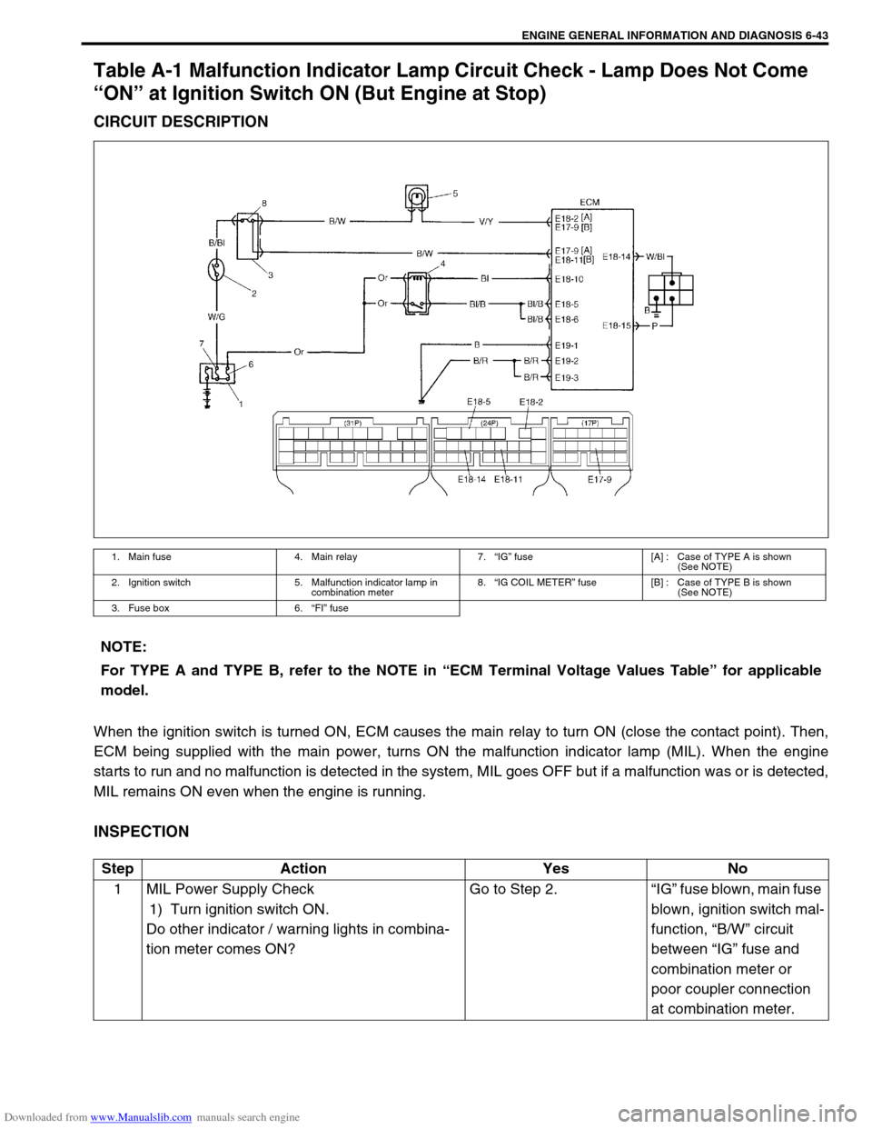
When the ignition switch is turned ON, ECM causes the main relay to turn ON (close the contact point). Then,
ECM being supplied with the main power, turns ON the malfunction indicator lamp (MIL). When the engine
starts to run and no malfunction is detected in the system, MIL goes OFF but if a malfunction was or is detected,
MIL remains ON even when the engine is running.
INSPECTION
1. Main fuse 4. Main relay 7.“IG” fuse [A] : Case of TYPE A is shown
(See NOTE)
2. Ignition switch 5. Malfunction indicator lamp in
combination meter8.“IG COIL METER” fuse [B] : Case of TYPE B is shown
(See NOTE)
3. Fuse box 6.“FI” fuse
NOTE:
For TYPE A and TYPE B, refer to the NOTE in “ECM Terminal Voltage Values Table” for applicable
model.
Step Action Yes No
1 MIL Power Supply Check
1) Turn ignition switch ON.
Do other indicator / warning lights in combina-
tion meter comes ON?Go to Step 2.“IG” fuse blown, main fuse
blown, ignition switch mal-
function, “B/W” circuit
between “IG” fuse and
combination meter or
poor coupler connection
at combination meter.
Page 677 of 687

Downloaded from www.Manualslib.com manuals search engine 6H-10 CHARGING SYSTEM
1) Set parking brake and place automatic transmission in
PARK (NEUTRAL on manual transmission). Turn off ignition,
turn off lights and all other electrical loads.
2) Check electrolyte level. If it is below low level line, add dis-
tilled water.
3) Attach end of one jumper cable to positive terminal of
booster battery and the other end of the same cable to posi-
tive terminal of discharged battery. (Use 12-volt battery only
to jump start engine).
4) Attach one end of the remaining negative cable to negative
terminal of booster battery, and the other end to a solid
engine ground (such as exhaust manifold) at least 45 cm (18
in.) away from battery of vehicle being started.
5) Start engine of vehicle with booster battery and turn off elec-
trical accessories. Then start engine of the vehicle with dis-
charged battery.
6) Disconnect jumper cables in the exact reverse order.
WITH CHARGING EQUIPMENT
WARNING:
Departure from these conditions or procedure
described below could result in:
–Serious personal injury (particularly to eyes) or
property damage from such causes as battery explo-
sion, battery acid, or electrical burns.
–Damage to electronic components of either vehicle.
Remove rings, watches, and other jewelry. Wear
approved eye protection.
Be careful so that metal tools or jumper cables do not
contact positive battery terminal (or metal in contact
with it) and any other metal on vehicle, because a short
circuit could occur.
WARNING:
Do not connect negative cable directly to negative termi-
nal of dead battery.
CAUTION:
When jump starting engine with charging equipment, be
sure equipment used is 12-volt and negative ground. Do
not use 24-volt charging equipment. Using such equip-
ment can cause serious damage to electrical system or
electronic parts.