radio SUZUKI JIMNY 2019 Owners Manual
[x] Cancel search | Manufacturer: SUZUKI, Model Year: 2019, Model line: JIMNY, Model: SUZUKI JIMNY 2019Pages: 421, PDF Size: 6.35 MB
Page 4 of 421
75F135
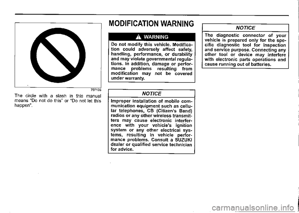
The circle with a slash in this manual means "Do not do this" or "Do not let this happen".
MODIFICATION WARNING
A WARNING
Do not modify this vehicle. Modification could adversely affect safety, handling, performance, or durability and may violate governmental regulations. In addition, damage or performance problems resulting from modification may not be covered under warranty.
NOTICE
Improper installation of mobile communication equipment such as cellular telephones, CB (Citizen's Band) radios or any other wireless transmitters may cause electronic interference with your vehicle's ignition system or any other electrical systems, resulting in vehicle performance problems. Consult a SUZUKI dealer or qualified service technician for advice.
NOTICE
The diagnostic connector of your vehicle is prepared only for the specific diagnostic tool for inspection and service purpose. Connecting any other tool or device may interfere with electronic parts operations and cause running out of batteries.
I
Page 13 of 421
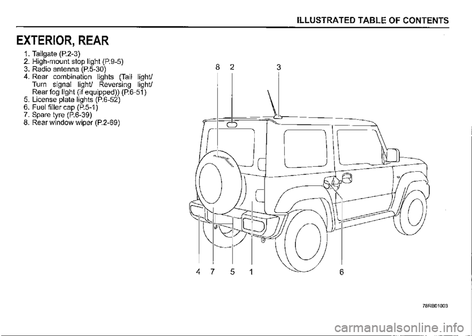
EXTERIOR, REAR
1. Tailgate (P.2-3) 2. High-mount stop light (P.9-5) 3. Radio antenna (P.5-30) 4. Rear combination lights (Tail light/ Turn signal light/ Reversing light/ Rear fog light (if equipped)) (P.6-51) 5. License plate lights (P.6-52) 6. Fuel filler cap (P.5-1) 7. Spare tyre (P.6-39) 8. Rear window wiper (P.2-69)
ILLUSTRATED TABLE OF CONTENTS
8 2 3
0
.... ,,.,,:\:<.
'----
4 7 5 1 6
78RB01003
Page 77 of 421
Keyless entry system
transmitter (if equipped)
(2)
79MH0237
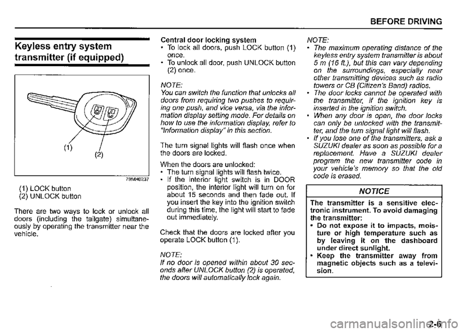
(1) LOCK button (2) UNLOCK button
There are two ways to lock or unlock all doors (including the tailgate) simultaneously by operating the transmitter near the vehicle.
Central door locking system To lock all doors, push LOCK button (1) once. • To unlock all door, push UNLOCK button (2) once.
NOTE: You can switch the function that unlocks all doors from requiring two pushes to requiring one push, and vice versa, via the information display setting mode. For details on how to use the information display, refer to "Information display" in this section.
The turn signal lights will flash once when the doors are locked.
When the doors are unlocked: The turn signal lights will flash twice. If the interior light switch is in DOOR position, the interior light will turn on for about 15 seconds and then fade out. If you insert the key into the ignition switch during this time, the light will start to fade out immediately.
Check that the doors are locked after you operate LOCK button (1 ).
NOTE: If no door is opened within about 30 seconds after UNLOCK button (2) is operated, the doors will automatically lock again.
BEFORE DRIVING
NOTE: The maximum operating distance of the keyless entry system transmitter is about 5 m (16 ft.), but this can vary depending on the surroundings, especially near other transmitting devices such as radio towers or CB (Citizen's Band) radios. The door locks cannot be operated with the transmitter, if the ignition key is inserted in the ignition switch. When any door is open, the door locks can only be unlocked with the transmitter, and the turn signal light will flash. If you lose one of the transmitters, ask a SUZUKI dealer as soon as possible for a replacement. Have a SUZUKI dealer program the new transmitter code in your vehicle's memory so that the old code is erased.
NOTICE
The transmitter is a sensitive electronic instrument. To avoid damaging the transmitter: Do not expose it to impacts, moisture or high temperature such as by leaving it on the dashboard under direct sunlight. Keep the transmitter away from magnetic objects such as a television.
2-6
Page 154 of 421
OPERATING YOUR VEHICLE
68PH00310
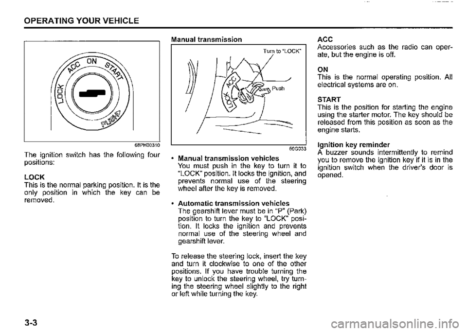
The ignition switch has the following four positions:
LOCK This is the normal parking position. It is the only position in which the key can be removed.
3-3
Manual transmission
Turn to "LOCK"
60G033
Manual transmission vehicles You must push in the key to turn it to "LOCK" position. It locks the ignition, and prevents normal use of the steering wheel after the key is removed.
Automatic transmission vehicles The gearshift lever must be in "P" (Park) position to turn the key to "LOCK" position. It locks the ignition and prevents normal use of the steering wheel and gearshift lever.
To release the steering lock, insert the key and turn it clockwise to one of the other positions. If you have trouble turning the key to unlock the steering wheel, try turning the steering wheel slightly to the right or left while turning the key.
ACC Accessories such as the radio can operate, but the engine is off.
ON This is the normal operating position. All electrical systems are on.
START This is the position for starting the engine using the starter motor. The key should be released from this position as soon as the engine starts.
Ignition key reminder A buzzer sounds intermittently to remind you to remove the ignition key if it is in the ignition switch when the driver's door is opened.
Page 219 of 421

TPMS limitations
The tyre pressure monitoring system may not function properly under certain circumstances. In the following situations, the low tyre pressure warning light may come on and remain on or may blink. When you replace a flat tyre with the spare tyre. When you include a spare tyre during a tyre rotation. When the TPMS sensor is damaged during a tyre replacement or liquid sealants are used to repair a flat tyre. When the electronic signal of TPMS sensor is disturbed in one of the following ways: -Electric devices or facilities using similar radio wave frequencies are nearby. -A metallic film that may cause radio wave interference is attached on the window. -A lot of snow or ice covers the vehicle, in particular, around the wheels or wheel housings. -Snow tyres that are not installed with genuine TPMS sensors or snow chains are used.
When you use non-genuine SUZUKI wheels or tyres. When the pressure of any tyre is too high. When there is a problem with the receiver of the TPMS controller.
TPMS setting (For instrument cluster -Type A)
You can set one of the initial value of tyre pressure below that is indicated on the tyre information label. -Comfort Mode -Load Mode
For details on how to set the mode, refer to "Setting mode" in "BEFORE DRIVING" section.
A WARNING
If the loading weight has changed, adjust the tyre pressure according to the tyre information label and set the initial value via the information display. If the loading weight, tyre pressure and initial value do not match, the tyre pressure monitoring system will not function properly.
OPERATING YOUR VEHICLE
TPMS setting (For instrument clus
ter• Type B)
• You can check the current tyre pressure on the information display. • You can set one of the initial value of tyre pressure below that is indicated on the tyre information label. -Comfort Mode
-Load Mode
A WARNING
If the loading weight has changed, adjust the tyre pressure according to the tyre information label and set the initial value via the information display. If the loading weight, tyre pressure and initial value do not nJatch, the tyre pressure monitoring system will not function properly.
3-68
Page 235 of 421
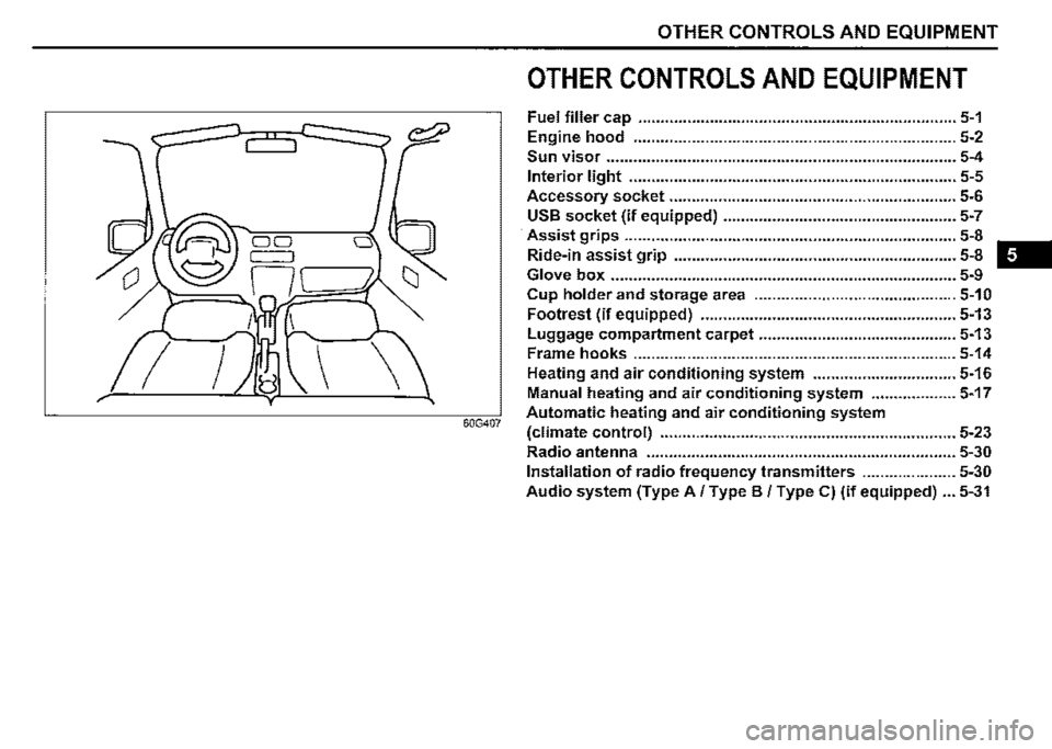
OTHER CONTROLS AND EQUIPMENT
OTHER CONTROLS AND EQUIPMENT
Fuel filler cap ....................................................................... 5-1
Engine hood ........................................................................ 5-2
Sun visor .............................................................................. 5-4
Interior light ......................................................................... 5-5
Accessory socket ................................................................ 5-6
USB socket (if equipped) .................................................... 5-7
Assist grips .......................................................................... 5-8 -
Ride-in assist grip ............................................................... 5-8
Glove box ............................................................................. 5-9
Cup holder and storage area ............................................. 5-10
Footrest (if equipped) ......................................................... 5-13
I
Luggage compartment carpet ............................................ 5-13
Frame hooks ........................................................................ 5-14
Heating and air conditioning system ................................ 5-16
Manual heating and air conditioning system ................... 5-17
60G407 Automatic heating and air conditioning system
(climate control) .................................................................. 5-23
Radio antenna ..................................................................... 5-30
Installation of radio frequency transmitters ..................... 5-30
Audio system (Type A/ Type B / Type C) (if equipped) ... 5-31
Page 265 of 421

Radio antenna
Type A
63J055
Type B
61MMOA113
OTHER CONTROLS AND EQUIPMENT
The radio antenna on the roof is removable. To remove the antenna, turn it counterclockwise. To reinstall the antenna, turn it clockwise firmly by hand.
NOTICE
To avoid damage to the radio antenna: Remove the antenna when using an automatic car wash. • Remove the antenna when the antenna hits anything such as a low ceiling in a parking garage or putting a car cover over your vehicle.
Installation of radio frequency
transmitters
NOTE: When you intend to use Radio Frequency (RF) transmitting equipment in your vehicle, refer to "Installation of Radio Frequency (RF) Transmitting Equipment" in the end of this book.
NOTICE
Improper installation of mobile communication equipment such as cellular telephones, CB (Citizen's Band) radios or any other wireless transmitters may cause electronic interference with your vehicle's ignition system or any other electrical systems resulting in vehicle performance problems. Consult a SUZUKI dealer or qualified service technician for advice.
5-30
Page 267 of 421
Safety information
,A WARNING
If you pay too much attention to operating the audio system or viewing the audio system display while driving, an accident can occur. If you set the sound volume too loud, it could prevent you from being aware of road and traffic conditions. • Keep your eyes on the road and your mind on the drive. Avoid paying too much attention to operating the audio system or viewing the audio system display. Familiarize yourself with the audio system controls and operation of the audio system before driving. • Preset your favorite radio stations before driving so that you can quickly tune to them using the presets. Set the sound volume to a level that will allow you to continue to be aware of road and traffic conditions while driving.
OTHER CONTROLS AND EQUIPMENT
Notes on discs
Precautions
When the inside of the vehicle is very
cold and the player is used soon after
switching on the heater, condensation
may form on the disc or the optical
parts of the player and proper playback
may not be possible. If condensation
forms on the disc, wipe it off with a soft
cloth. If condensation forms on the opti
cal parts of the player, do not use the
player for about one hour. This will
allow the condensation to disappear
normally.
Driving on extremely bumpy roads
which cause severe vibrations may
cause sound to skip.
This unit uses a precision mechanism.
Even in the event that trouble arises,
never open the case, disassemble the
unit, or lubricate the rotating parts.
Bring the unit to a SUZUKI dealer.
Cautions on handling
[rr]oiL DIGITAL AUDIO (A)
52D274
This unit has been designed specifically for
playback of compact discs bearing mark
(A) shown above.
No other discs can be played.
5-32
Page 270 of 421
OTHER CONTROLS AND EQUIPMENT
0 Bluetooth"
The Bluetooth® word mark and logo are
registered trademarks and are owned by
the Bluetooth SIG, Ink.
Stop using this unit and a Bluetooth®
ready device whenever requested.
This unit shares the communication fre
quency with other private or public wireless
communication equipment such as a wire
less LAN and other wireless communica
tion radios.
You should stop using this unit whenever
you are notified that your unit disturbs
other wireless communication immediately.
5-35
CE:
Access to http://www.ptc.panasonic.eu/,
enter the below
Model No. into the keyword search box,
you can download the latest "DECLARA
TION of CONFORMITY" (DoC).
Set No. AZ1601
Page 272 of 421
OTHER CONTROLS AND EQUIPMENT
Part 15 of the FCC Rules
FCC ID: ACJ932AZ1601
NOTE: Properly shielded and grounded cables and connectors must be used for connection to host computers and/or peripherals in order to meet FCC emission limits.
.A. WARNING
RF Exposure This equipment complies with FCC radiation exposure limits set forth for an uncontrolled environment and meets the FCC radio frequency (RF) Exposure Guidelines. This equipment has very low levels of RF energy that it deemed to comply without maximum permissive exposure evaluation (MPE). [But it is desirable that it should be installed and operated keeping the radiator at least 20 cm or more away from person's body.]
.A. CAUTION
Changes or modifications not expressly approved by the party responsible for compliance could void the user's authority to operate the equipment.
5-37
.A. WARNING
This is a class I laser product. Use of controls or adjustments or performance of procedures other than those specified herein may result in hazardous radiation exposure. Do not open covers and do not attempt to repair this unit by yourself. Ask an authorized dealer for the repair.
0 Bluetooth'
The Bluetooth® word mark and logo are
registered trademarks and are owned by
the Bluetooth SIG, Ink.
NOTE:
This equipment complies with FCC radiation exposure limits set forth for uncontrolled equipment and meets the FCC radio frequency (RF) Exposure Guidelines in Supplement C to OET65. This equipment has very low level of RF energy which does not comply with maximum permissive exposure (MPE) evaluation. But it is desirable that it should be installed and operated with at least 20cm and more between the radiator and person's body (excluding extremities: hands, wrists, feet and ankles).