ESP SUZUKI KIZASHI 2010 1.G Owner's Manual
[x] Cancel search | Manufacturer: SUZUKI, Model Year: 2010, Model line: KIZASHI, Model: SUZUKI KIZASHI 2010 1.GPages: 388, PDF Size: 4.94 MB
Page 135 of 388
3-4
OPERATING YOUR VEHICLE
57L20-03E
Keyless Push Start SystemProvided the keyless start system remote
controller is within the “interior workable
area” (Refer to the related explanation in
this section), you can use the engine
switch for starting the engine and selecting
a power supply mode (“ACC” or “ON”). In
addition, the following functions can be
used:
Keyless entry function. Refer to “KeylessStart System Remote Controller” in the
“Before Driving” section for details.
Locking and unlocking doors using a request switch. Refer to “Keyless Start
System Remote Controller” in the
“Before Driving” section for details.
Opening the trunk lid from outside using the trunk lid request switch.
Immobilizer (anti-theft) function. Refer to “Immobilizer System” in the “Before Driv-
ing” section for details.Engine Switch IlluminationThe engine switch is illuminated lit in the
following situations:
The driver’s door is open (only when the
engine is not in operation).
For 15 seconds after the driver’s door is closed (only when the engine is not in
operation).
The position lights are on.
The illumination will fade out when it is not
required.
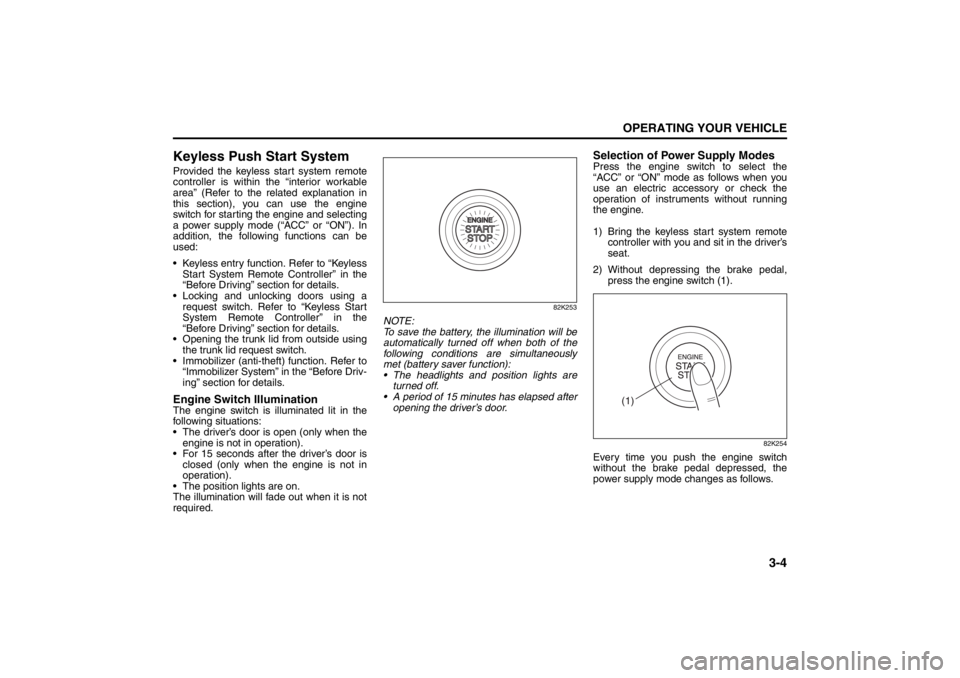
82K253
NOTE:
To save the battery, the illumination will be
automatically turned off when both of the
following conditions are simultaneously
met (battery saver function):
The headlights and position lights are turned off.
A period of 15 minutes has elapsed after opening the driver’s door.
Selection of Power Supply ModesPress the engine switch to select the
“ACC” or “ON” mode as follows when you
use an electric accessory or check the
operation of instruments without running
the engine.
1) Bring the keyless start system remote controller with you and sit in the driver’s
seat.
2) Without depressing the brake pedal, press the engine switch (1).
82K254
Every time you push the engine switch
without the brake pedal depressed, the
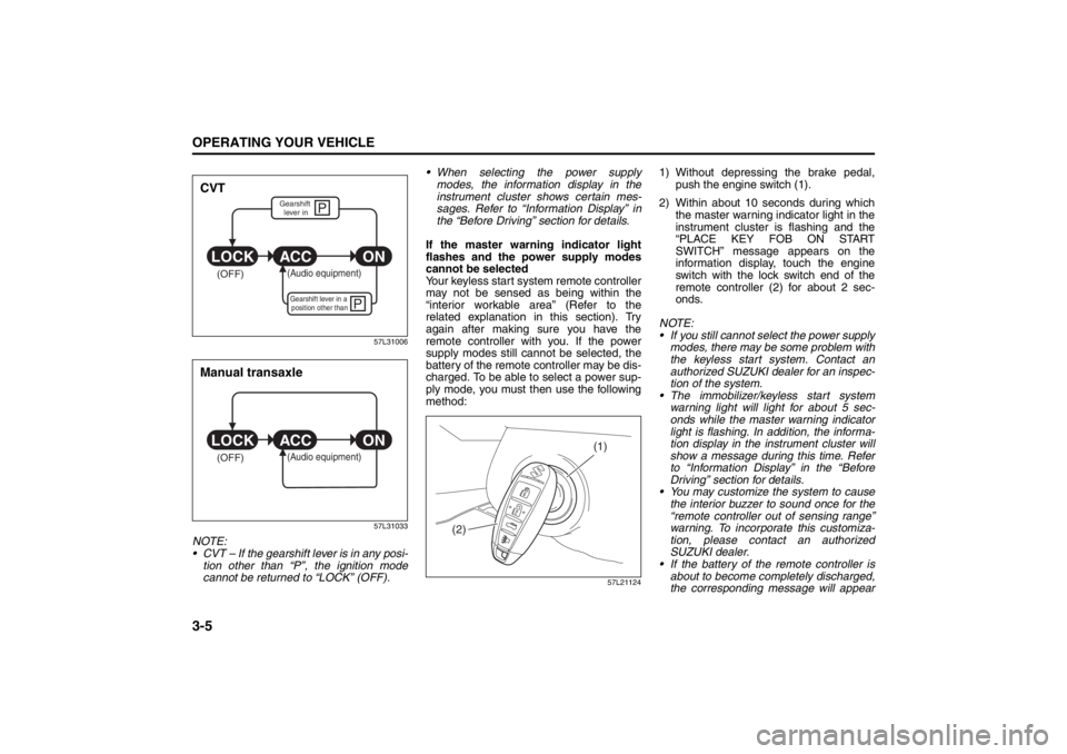
power supply mode changes as follows.
(1)
Lighting/Turn Signal Control Lever: 8
Windshield Wiper and Washer Lever: 8
Page 136 of 388
3-5OPERATING YOUR VEHICLE
57L20-03E
57L31006
57L31033
NOTE:
CVT – If the gearshift lever is in any posi-tion other than “P”, the ignition mode
cannot be returned to “LOCK” (OFF). When selecting the power supply
modes, the information display in the
instrument cluster shows certain mes-
sages. Refer to “Information Display” in
the “Before Driving” section for details.
If the master warning indicator light
flashes and the power supply modes
cannot be selected
Your keyless start system remote controller
may not be sensed as being within the
“interior workable area” (Refer to the
related explanation in this section). Try
again after making sure you have the
remote controller with you. If the power
supply modes still can not be selected, the
battery of the remote controller may be dis-
charged. To be able to select a power sup-
ply mode, you must then use the following
method:
57L21124
1) Without depressing the brake pedal, push the engine switch (1).
2) Within about 10 seconds during which the master warning indicator light in the
instrument cluster is flashing and the
“PLACE KEY FOB ON START
SWITCH” message appears on the
information display, touch the engine
switch with the lock switch end of the
remote controller (2) for about 2 sec-
onds.
NOTE:
If you still cannot select the power supply modes, there may be some problem with
the keyless start system. Contact an
authorized SUZUKI dealer for an inspec-
tion of the system.
The immobilizer/keyless start system warning light will light for about 5 sec-
onds while the master warning indicator
light is flashing. In addition, the informa-
tion display in the instrument cluster will
show a message during this time. Refer
to “Information Display” in the “Before
Driving” section for details.
You may customize the system to cause
the interior buzzer to sound once for the
“remote controller out of sensing range”
warning. To incorporate this customiza-
tion, please contact an authorized
SUZUKI dealer.
If the battery of the remote controller is
about to become completely discharged,
the corresponding message will appear
P
P
(OFF)
ON
ACC
LOCK
(Audio equipment)Gearshift lever in a
position other thanGearshift lever in
CVT
(OFF)
ON
ACC
LOCK
(Audio equipment)
Manual transaxle
(1)
(2)
Windshield Wiper and Washer Lever: 8
Rear Window Wiper/Washer Switch: 8
Page 138 of 388
3-7OPERATING YOUR VEHICLE
57L20-03E
the following conditions, you may not be
able to start the engine or select the
power supply modes, and the “remote
controller outside” warning may be
given.
– The remote controller’s battery is low.
– The remote controller is affected bystrong radio signals or noise.
– The remote controller is in contact with or covered by a metallic object.
– The remote controller is in stowage like the glove box or a door pocket.
– The remote controller is in the sun
visor pocket or on the floor.
Even when the remote controller is out- side the “interior workable area”, if it is in
any of the following conditions, you may
be able to start the engine or select the
power supply mode. The “remote con-
troller outside” warning may not be given
at that time.
– The remote controller is outside the
vehicle but very close to a door.
– The remote controller is on the instru- ment panel.
Starting the EngineBefore Starting the Engine1) Make sure the parking brake is set fully.
2) Manual Transaxle – Shift to “N” (Neu- tral) and fully depress the clutch pedal.
Hold the clutch and brake pedals fully
depressed.
CVT – If the gearshift lever is not in the
“P” (Park) position, shift it to “P”. Hold
the brake pedal fully depressed.
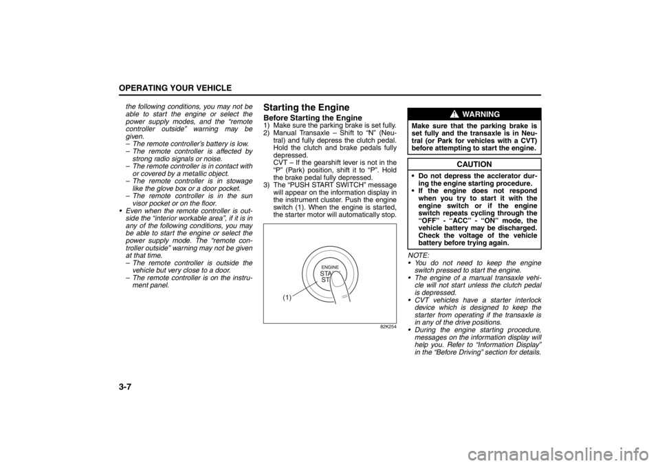
3) The “PUSH START SWITCH” message will appear on the information display in
the instrument cluster. Push the engine
switch (1). When the engine is started,
the starter motor will automatically stop.
82K254
NOTE:
You do not need to keep the engine
switch pressed to start the engine.
The engine of a manual transaxle vehi- cle will not start unless the clutch pedal
is depressed.
CVT vehicles have a starter interlock device which is designed to keep the
starter from operating if the transaxle is
in any of the drive positions.
During the engine starting procedure,
messages on the inform ation display will
help you. Refer to “Information Display”
in the “Before Driving” section for details.
(1)
WARNING
Make sure that the parking brake is
set fully and the tr ansaxle is in Neu-
tral (or Park for vehicles with a CVT)
before attempting to start the engine.
CAUTION
Do not depress the acclerator dur-
ing the engine st arting procedure.
If the engine does not respond when you try to start it with the
engine switch or if the engine
switch repeats cycling through the
“OFF” - “ACC” - “ON” mode, the
vehicle battery may be discharged.
Check the voltage of the vehicle
battery before trying again.
Cruise Control: 7, 8
Page 154 of 388
3-23OPERATING YOUR VEHICLE
57L20-03E
steadily increase. When you release the
switch, the new speed will be maintained.
To reset at a slower cruising speed, press
repeatedly or hold push down the “RES +/
SET –” switch (3) until the vehicle has
slowed to the desired speed, then release
the switch. The new speed will be main-
tained.
NOTE:
You can adjust the set speed by approxi-
mately 1.0 mph (1.6 km/h) by pushing a
cruise control switch quickly.
Cancellation of the Cruise Control
The “SET” indicator light will go off and the
cruise control will be canceled temporarily
with following procedures:
Push the “CANCEL” switch (2).
Depress the brake pedal.
For manual transaxle, depress the clutch
pedal.
For CVT, downshift from 3rd to 2nd in the
manual mode.
The vehicle speed falls more than about
20 percent from the set speed.
Any time the vehicle speed falls below
25 mph (40 km/h).
When the vehicle skids and ESP
® (if
equipped) is activated.
To resume the previously set speed, push
up the “RES +/SET –” switch (3) and turn
on the “SET” indicator light. Besides, the
vehicle speed has to be above 25 mph (40km/h) when the vehicle is not in the above
conditions.
To turn off the cruise control system, push
the “CRUISE” switch (1) and make sure
the “CRUISE” indicator light is off.
Also, if the malfunction indicator light in the
instrument cluster comes on or blinks, the
cruise control system will be turned off.
NOTE:
If you turn off the cruise control system, the
previously set speed in the memory is
cleared. Reset your cruising speed again.
Parking Sensors
(if equipped)
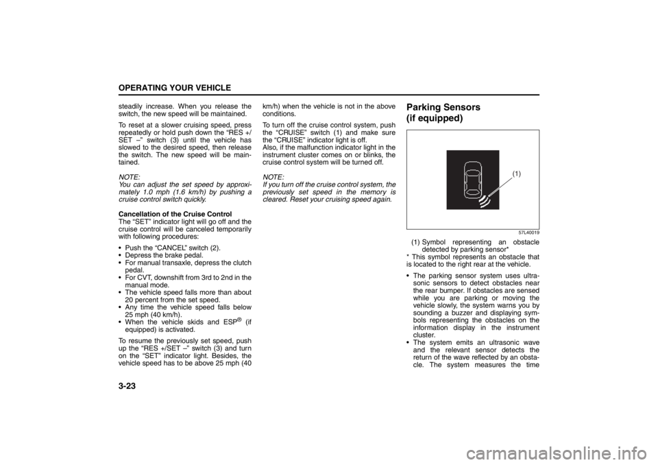
57L40019
(1) Symbol representing an obstacle
detected by parking sensor*
* This symbol represents an obstacle that
is located to the right rear at the vehicle.
The parking sensor system uses ultra-
sonic sensors to detect obstacles near
the rear bumper. If obstacles are sensed
while you are parking or moving the
vehicle slowly, the system warns you by
sounding a buzzer and displaying sym-
bols representing the obstacles on the
information display in the instrument
cluster.
The system emits an ultrasonic wave
and the relevant sensor detects the
return of the wave reflected by an obsta-
cle. The system measures the time
(1)
Page 158 of 388
3-27OPERATING YOUR VEHICLE
57L20-03E
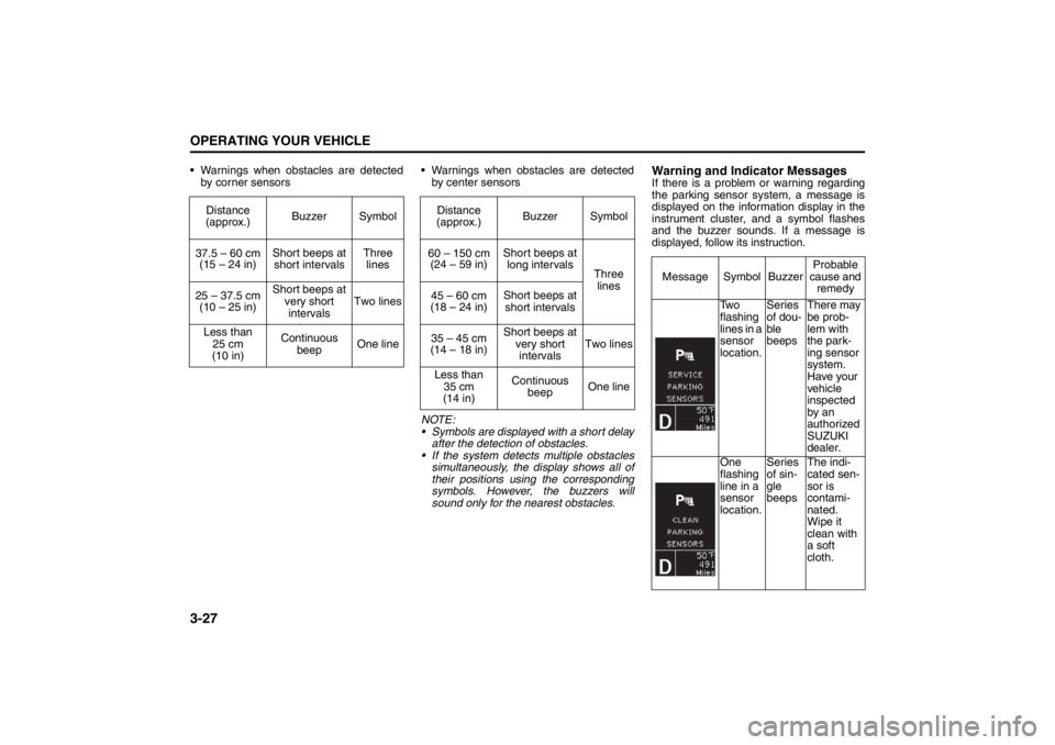
Warnings when obstacles are detected
by corner sensors Warnings when obstacles are detected
by center sensors
NOTE:
Symbols are displayed with a short delay
after the detection of obstacles.
If the system detects multiple obstacles
simultaneously, the display shows all of
their positions using the corresponding
symbols. However, the buzzers will
sound only for the nearest obstacles.
Warning and Indicator MessagesIf there is a problem or warning regarding
the parking sensor system, a message is
displayed on the information display in the
instrument cluster, and a symbol flashes
and the buzzer sounds. If a message is
displayed, follow its instruction. Distance
(approx.)Buzzer Symbol
37.5 – 60 cm
(15 – 24 in)Short beeps at
short intervalsThree
lines
25 – 37.5 cm
(10 – 25 in)Short beeps at
very short
intervalsTwo lines
Less than
25 cm
(10 in)Continuous
beepOne line
Distance
(approx.)Buzzer Symbol
60 – 150 cm
(24 – 59 in)Short beeps at
long intervals
Three
lines
45 – 60 cm
(18 – 24 in)Short beeps at
short intervals
35 – 45 cm
(14 – 18 in)Short beeps at
very short
intervalsTwo lines
Less than
35 cm
(14 in)Continuous
beepOne line
Message Symbol BuzzerProbable
cause and
remedy
Tw o
flashing
lines in a
sensor
location.Series
of dou-
ble
beepsThere may
be prob-
lem with
the park-
ing sensor
system.
Have your
vehicle
inspected
by an
authorized
SUZUKI
dealer.
One
flashing
line in a
sensor
location.Series
of sin-
gle
beepsThe indi-
cated sen-
sor is
contami-
nated.
Wipe it
clean with
a soft
cloth.
Page 162 of 388
3-31OPERATING YOUR VEHICLE
57L20-03E
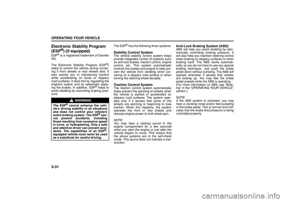
Electronic Stability Program
(ESP
®) (if equipped)
ESP
® is a registered trademark of Daimler
AG.
The Electronic Stability Program (ESP
®)
helps to control the vehicle during corner-
ing if front wheels or rear wheels skid. It
also assists you in maintaining traction
while accelerating on loose or slippery
road surfaces. It does this by regulating the
engine’s output, and by selectively apply-
ing the brakes. In addition, ESP
® helps to
avoid skidding by controlling braking pres-
sure.The ESP
® has the following three systems:
Stability Control SystemThe vehicle stability control system helps
provide integrated control of systems such
as anti-lock brakes, traction control, engine
control, etc. This system automatically
controls the brakes and engine to help pre-
vent the vehicle from skidding when cor-
nering on a slippery road surface or when
turning the steering wheel abruptly.Traction Control SystemThe traction control system automatically
helps prevent the spinning of wheels when
the vehicle is started or accelerated on
slippery road surfaces. The system oper-
ates only if it senses that some of the
wheels are spinning or beginning to lose
traction. When this happens, the system
operates the front or rear brakes and
reduces engine power to limit wheel spin.
NOTE:
You may hear a clicking sound in the
engine compartment for a few seconds
when you start the engine or just after the
vehicle begins to move. This means that
the above systems are in the self-check
mode. This sound does not indicate a mal-
function.
Anti-Lock Braking System (ABS)ABS will help you avoid skidding by elec-
tronically controlling braking pressure. It
will also help you maintain steering control
when braking on slippery surfaces or when
braking hard. The ABS works automati-
cally, so you do not have to use any special
braking technique. Just push the brake
pedal down without pumping. The ABS will
operate whenever it senses that wheels
are locking up. You may feel the brake
pedal pulsate while the ABS is operating.
(For more information on ABS, see “Brak-
ing” in the “OPERATING YOUR VEHICLE”
section.)
NOTE:
If the ABS system is activated, you may
hear a clunking noise and/or feel pulsating
in the brake pedal. This is normal and indi-
cates that the brake fluid pressure is being
controlled properly.
WARNING
The ESP
® cannot enhance the vehi-
cle’s driving stability in all situations
and does not control your vehicle’s
entire braking system. The ESP
® can-
not prevent accidents, including
those resulting from excessive speed
in turns, or hydroplaning. Only a safe
and attentive driver can prevent acci-
dents. The capabilities of an ESP
®-
equipped vehicle must never be used
as a substitute for careful driving.
Page 163 of 388
3-32
OPERATING YOUR VEHICLE
57L20-03E
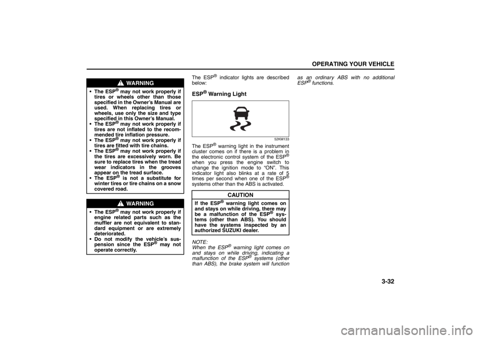
The ESP
® indicator lights are described
below:
ESP
® Warning Light
52KM133
The ESP
® warning light in the instrument
cluster comes on if there is a problem in
the electronic control system of the ESP
®
when you press the engine switch to
change the ignition mode to “ON”. This
indicator light also blinks at a rate of 5
times per second when one of the ESP
®
systems other than the ABS is activated.
NOTE:
When the ESP
® warning light comes on
and stays on while driving, indicating a
malfunction of the ESP
® systems (other
than ABS), the brake system will functionas an ordinary ABS with no additional
ESP
® functions.
WARNING
The ESP
® may not work properly if
tires or wheels other than those
specified in the Owner’s Manual are
used. When replacing tires or
wheels, use only the size and type
specified in this Owner’s Manual.
The ESP® may not work properly if
tires are not inflated to the recom-
mended tire inflation pressure.
The ESP® may not work properly if
tires are fitted with tire chains.
The ESP® may not work properly if
the tires are excessively worn. Be
sure to replace tires when the tread
wear indicators in the grooves
appear on the tread surface.
The ESP® is not a substitute for
winter tires or tire chains on a snow
covered road.
WARNING
The ESP
® may not work properly if
engine related parts such as the
muffler are not equivalent to stan-
dard equipment or are extremely
deteriorated.
Do not modify the vehicle’s sus-
pension since the ESP
® may not
operate correctly.
CAUTION
If the ESP
® warning light comes on
and stays on while driving, there may
be a malfunction of the ESP
® sys-
tems (other than ABS). You should
have the systems inspected by an
authorized SUZUKI dealer.
Page 164 of 388
3-33OPERATING YOUR VEHICLE
57L20-03E
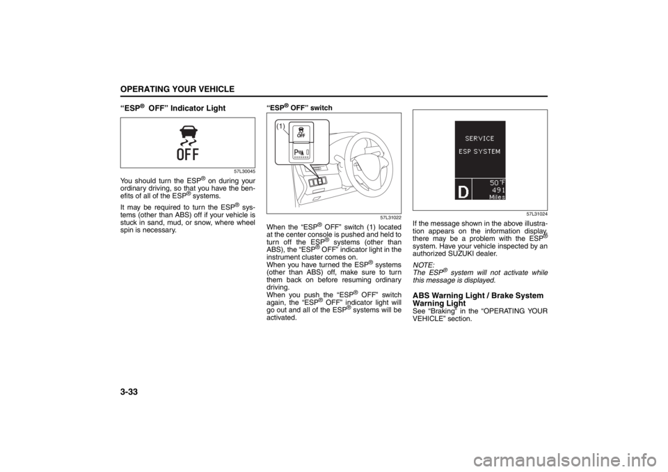
“ESP
® OFF” Indicator Light
57L30045
You should turn the ESP
® on during your
ordinary driving, so that you have the ben-
efits of all of the ESP
® systems.
It may be required to turn the ESP
® sys-
tems (other than ABS) off if your vehicle is
stuck in sand, mud, or snow, where wheel
spin is necessary.“ESP
® OFF” switch
57L31022
When the “ESP
® OFF” switch (1) located
at the center console is pushed and held to
turn off the ESP® systems (other than
ABS), the “ESP
® OFF” indicator light in the
instrument cluster comes on.
When you have turned the ESP
® systems
(other than ABS) off, make sure to turn
them back on before resuming ordinary
driving.
When you push the “ESP
® OFF” switch
again, the “ESP
® OFF” indicator light will
go out and all of the ESP
® systems will be
activated.
57L31024
If the message shown in the above illustra-
tion appears on the information display,
there may be a problem with the ESP
®
system. Have your vehicle inspected by an
authorized SUZUKI dealer.
NOTE:
The ESP
® system will not activate while
this message is displayed.
ABS Warning Light / Brake System
Warning LightSee “Braking” in the “OPERATING YOUR
VEHICLE” section.
(1)
Page 166 of 388
3-35OPERATING YOUR VEHICLE
57L20-03E
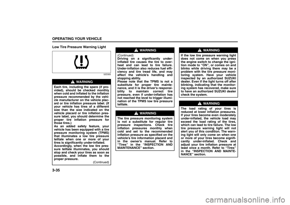
Low Tire Pressure Warning Light
52D305
WARNING
Each tire, including the spare (if pro-
vided), should be checked monthly
when cold and inflated to the inflation
pressure recommended by the vehi-
cle manufacturer on the vehicle plac-
ard or tire inflation pressure label. (If
your vehicle has tires of a different
size than the size indicated on the
vehicle placard or tire inflation pres-
sure label, you should determine the
proper tire inflation pressure for
those tires.)
As an added safety feature, your
vehicle has been equipped with a tire
pressure monitoring system (TPMS)
that illuminates a low tire pressure
telltale when one or more of your
tires is significantly under-inflated.
Accordingly, when the low tire pres-
sure telltale illuminates, you should
stop and check your tires as soon as
possible, and inflate them to the
proper pressure.
(Continued)
WARNING
(Continued)
Driving on a significantly under-
inflated tire causes the tire to over-
heat and can lead to tire failure.
Under-inflation also reduces fuel effi-
ciency and tire tread life, and may
affect the vehicle’s handling and
stopping ability.
Please note that the TPMS is not a
substitute for proper tire mainte-
nance, and it is the driver’s responsi-
bility to maintain correct tire
pressure, even if under-inflation has
not reached the level to trigger illumi-
nation of the TPMS low tire pressure
telltale.
WARNING
The tire pressure monitoring system
is not a substitute for regular tire
pressure inspections. Check tire
inflation pressures monthly when
cold and set to the recommended
inflation pressure as specified on the
vehicle’s tire information placard and
in the owner’s manual. Refer to
“Tires” in the “INSPECTION AND
MAINTENANCE” section.
WARNING
If the low tire pressure warning light
does not come on when you press
the engine switch to change the igni-
tion mode to “ON”, or comes on and
blinks while driving there may be a
problem with the tire pressure moni-
toring system. Have your vehicle
inspected by an authorized SUZUKI
dealer. Even if the light turns off after
blinking, indicating that the monitor-
ing system has recovered, make sure
to have an authorized SUZUKI dealer
check the system.
WARNING
The load rating of your tires is
reduced at lower inflation pressures.
If your tires become even moderately
under-inflated, the vehicle load may
exceed the load rating of the tires,
which can lead to tire failure. The low
tire pressure warning light will not
alert you of this condition. The warn-
ing light will only come on when one
or more of your tires become signifi-
cantly under-inflated. Check and
adjust your tire inflation pressure at
least once a month. Refer to “Tires”
in the “INSPECTION AND MAINTE-
NANCE” section.
Page 170 of 388

3-39OPERATING YOUR VEHICLE
57L20-03E
NOTE:
A TPMS sensor is not installed in the spare
tire. You should use the spare tire only in
an emergency situation, and should
replace the spare tire as soon as possible
to restore normal TPMS operation.For Vehicles Sold in U.S.A.This device complies with Part 15 of the
FCC Rules.
Operation is subject to the following two
conditions:
1) This device may not cause harmful
interference.
2) This device must accept any interfer-
ence received, including interference
that may cause undesired operation.
NOTE:
Changes or modifications not expressly
approved by the party responsible for com-
pliance could void the user’s authority to
operate the equipment.
Traveling to CANADAPlease note that service for the tire pres-
sure monitoring system may not be avail-
able in CANADA should there be any
problems or malfunctions in the system.
WARNING
Only use tires and wheels recom-
mended by SUZUKI as standard or
optional equipment for your vehicle.
Use of tires or wheels not recom-
mended by SUZUKI can result in
TPMS failure. Refer to “Tires” in the
“INSPECTION AND MAINTENANCE”
section for additional information.