service SUZUKI KIZASHI 2010 1.G Owner's Manual
[x] Cancel search | Manufacturer: SUZUKI, Model Year: 2010, Model line: KIZASHI, Model: SUZUKI KIZASHI 2010 1.GPages: 388, PDF Size: 4.94 MB
Page 287 of 388
7-2
INSPECTION AND MAINTENANCE
57L20-03E
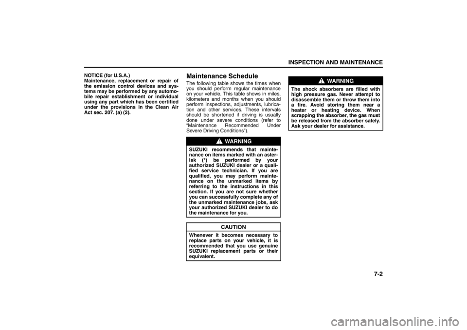
NOTICE (for U.S.A.)
Maintenance, replacement or repair of
the emission control devices and sys-
tems may be performed by any automo-
bile repair establishment or individual
using any part which has been certified
under the provisions in the Clean Air
Act sec. 207. (a) (2).
Maintenance ScheduleThe following table shows the times when
you should perform regular maintenance
on your vehicle. This table shows in miles,
kilometers and months when you should
perform inspections, adjustments, lubrica-
tion and other services. These intervals
should be shortened if driving is usually
done under severe conditions (refer to
“Maintenance Recommended Under
Severe Driving Conditions”).
WARNING
SUZUKI recommends that mainte-
nance on items marked with an aster-
isk (*) be performed by your
authorized SUZUKI dealer or a quali-
fied service technician. If you are
qualified, you may perform mainte-
nance on the unmarked items by
referring to the instructions in this
section. If you are not sure whether
you can successfully complete any of
the unmarked maintenance jobs, ask
your authorized SUZUKI dealer to do
the maintenance for you.
CAUTION
Whenever it becomes necessary to
replace parts on your vehicle, it is
recommended that you use genuine
SUZUKI replacement parts or their
equivalent.
WARNING
The shock absorbers are filled with
high pressure gas. Never attempt to
disassemble them or throw them into
a fire. Avoid storing them near a
heater or heating device. When
scrapping the absorber, the gas must
be released from the absorber safely.
Ask your dealer for assistance.
Driving on Hills: NO
Driving on Slippery Roads: NO
Page 289 of 388
7-4
INSPECTION AND MAINTENANCE
57L20-03E
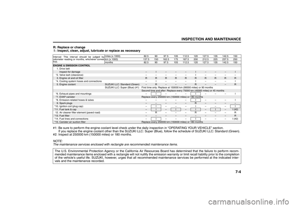
R: Replace or change
I : Inspect, clean, adjust, lubricate or replace as necessary
#1: Be sure to perform the engine coolant level check under the daily inspection in “OPERATING YOUR VEHICLE” section.
If you replace the engine coolant other than the SUZUKI LLC: Super (Blue), follow the schedule of SUZUKI LLC: Standard (Green).
#2: Inspect at 250000 km (150000 miles) or 180 months.
NOTE:
The maintenance services enclosed with rectangle are recommended maintenance items.Interval: This interval should be judged by
odometer reading or months, whichever comes
first.miles (x 1000) 82.5 90 97.5 105 112.5 120 127.5 135 142.5 150
km (x 1000) 137.5 150 162.5 175 187.5 200 212.5 225 237.5 250
months 82.5 90 97.5 105 112.5 120 127.5 135 142.5 150ENGINE & EMISSION CONTROL
1. Drive beltInspect for damage
–
I
–
–
–
I
–
–
–
I
*2. Valve lash (clearance) – – – – – I – – – –3.Engine oil and oil filter
R
R
R
R
R
R
R
R
R
R
*4. Cooling system hoses and connections – I – – – I – – – I5.Engine coolant
SUZUKI LLC: Standard (Green)
–
R
–
–
–
R
–
–
–
R
SUZUKI LLC: Super (Blue) (#1) First time only: Replace at 150000 km (90000 miles) or 90 months
Second time and after: Replace every 75000 km (45000 miles) or 45 months
*6. Exhaust pipes and mountings – I – – – I – – – I*7.
EVAP canister
Replace every 250000 km (150000 miles) or 180 months
*8. Emission-related hoses & tubes – – – – – I – – – I9.Spark plugs
–
–
–
–
–
R
–
–
–
–
*10. Ignition coil (plug cap) – I – – – I – – – I*11.
Fuel tank & cap
–
I
–
I
–
I
–
I
–
I (#2)
12. Air cleaner filter element (paved road) – R – – – R – – – R*13.
Fuel filter
–
–
–
–
–
–
–
–
–
R
*14. Fuel lines and connections – I – – – I – – – I (#2)*15.
Canister air suction filter
Replace every 250000 km (150000 miles) or 180 months
The U.S. Environmental Protection Agency or the California Air Resources Board has determined that the failure to perform recom-
mended maintenance items enclosed with a rectangle will not nullify the emission warranty or limit recall liability prior to the completion
of the vehicle’s useful life. SUZUKI, however, urges that all recommended maintenance services be performed at the indicated inter-
vals and the maintenance recorded.
Driving on Slippery Roads: NO
Page 291 of 388
7-6
INSPECTION AND MAINTENANCE
57L20-03E
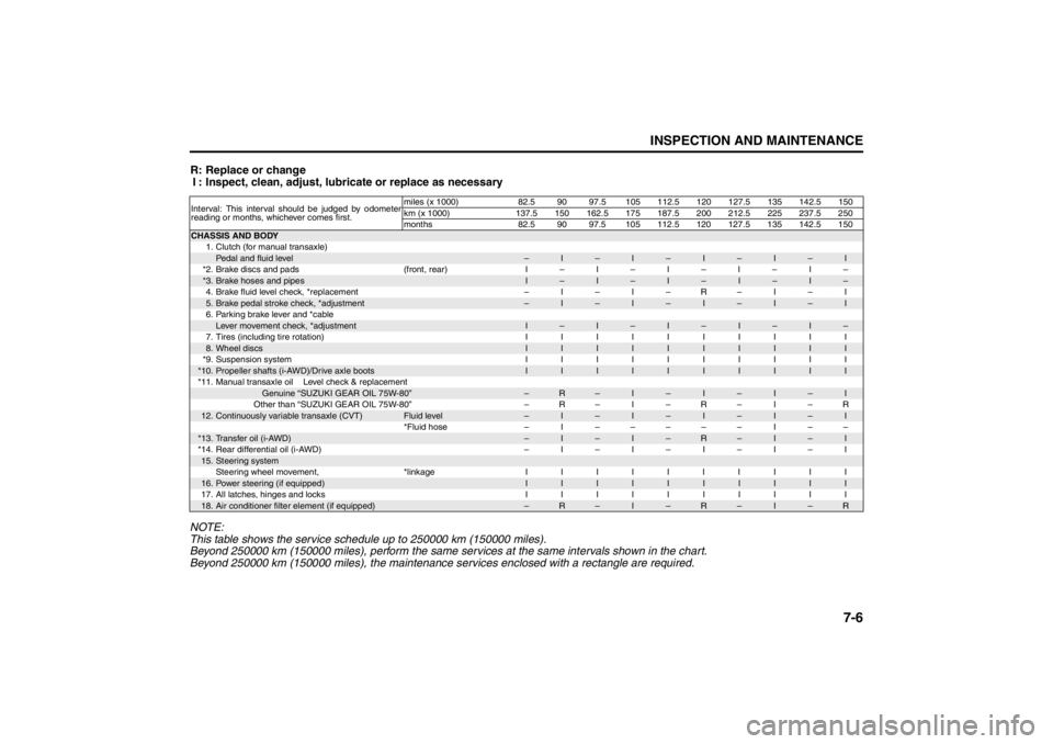
R: Replace or changeI : Inspect, clean, adjust, lubr icate or replace as necessary
NOTE:
This table shows the service schedule up to 250000 km (150000 miles).
Beyond 250000 km (150000 miles), perform the same services at the same intervals shown in the chart.
Beyond 250000 km (150000 miles), the maintenance se rvices enclosed with a rectangle are required.Interval: This interval should be judged by odometer
reading or months, whichever comes first.miles (x 1000) 82.5 90 97.5 105 112.5 120 127.5 135 142.5 150
km (x 1000) 137.5 150 162.5 175 187.5 200 212.5 225 237.5 250
months 82.5 90 97.5 105 112.5 120 127.5 135 142.5 150CHASSIS AND BODY
1. Clutch (for manual transaxle)
Pedal and fluid level
–
I
–
I
–
I
–
I
–
I
*2. Brake discs and pads (front, rear) I – I – I – I – I –
*3.
Brake hoses and pipes
I
–
I
–
I
–
I
–
I
–
4. Brake fluid level check, *replacement – I – I – R – I – I
5.Brake pedal stroke check, *adjustment
–
I
–
I
–
I
–
I
–
I
6. Parking brake lever and *cable
Lever movement check, *adjustment
I
–
I
–
I
–
I
–
I
–
7.Tires (including tire rotation) IIIIIIIIII
8.Wheel discs
I
I
I
I
I
I
I
I
I
I
*9. Suspension system I I I I I I I I I I
*10.
Propeller shafts (i-AWD)/Drive axle boots
I
I
I
I
I
I
I
I
I
I
*11. Manual transaxle oil Level check & replacement
Genuine “SUZUKI GEAR OIL 75W-80”
–
R
–
I
–
I
–
I
–
I
Other than “SUZUKI GEAR OIL 75W-80” – R – I – R – I – R
12.
Continuously variable transaxle (CVT)
Fluid level
–
I
–
I
–
I
–
I
–
I
*Fluid hose – I ––––– I ––
*13.
Transfer oil (i-AWD)
–
I
–
I
–
R
–
I
–
I
*14. Rear differential oil (i-AWD) – I – I – I – I – I
15.
Steering systemSteering wheel movement, *linkage I I I I I I I I I I
16.
Power steering (if equipped)
I
I
I
I
I
I
I
I
I
I
17. All latches, hinges and locks I I I I I I I I I I
18.
Air conditioner filter element (if equipped)
–
R
–
I
–
R
–
I
–
R
Page 292 of 388
7-7INSPECTION AND MAINTENANCE
57L20-03E
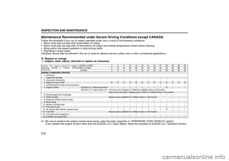
Maintenance Recommended under Severe Driving Conditions except CANADAFollow this schedule if your car is mainly oper ated under one or more of the following conditions:
When most trips are less than 6 kilometers (4 miles)
When most trips are less than 16 kilometers (10 mile s) and outside temperature remain below freezing.
Idling and/or low-speed operation in stop-and-go traffic.
Operating in dusty areas.
Schedule should also be followed if the car is used for delivery service, police, taxi or other commercial applications.
R: Replace or change I : Inspect, clean, adjust, lubr icate or replace as necessary
#1: Be sure to perform the engine coolant level check under the daily inspection in “OPERATING YOUR VEHICLE” section.
If you replace the engine coolant other than the SUZUKI LLC: Super (Blue), follow the schedule of SUZUKI LLC: Standard (Green).Interval: This interval should be judged by
odometer reading or months, whichever
comes first. miles (x 1000) 3 6 9 12151821242730333639
km (x 1000) 5 10 15 20 25 30 35 40 45 50 55 60 65
months 3 6 9 12151821242730333639ENGINE & EMISSION CONTROL
1. Drive belt
Inspect for damage
–
–
–
–
–
–
–
–
–
I
–
–
–
*2.Valve lash (clearance) –––––––––––––
3.Engine oil and oil filter
R
R
R
R
R
R
R
R
R
R
R
R
R
*4. Cooling system hoses and connections – – – – I – – – – I – – –
5.Engine coolant
SUZUKI LLC: Standard (Green)
–
–
–
–
–
–
–
–
–
R
–
–
–
SUZUKI LLC: Super (Blue) (#1) First time only: Replace at 150000 km (90000 miles) or 90 months
Second time and after: Replace every 75000 km (45000 miles) or 45 months
*6. Exhaust pipes and mountings – – – – I – – – – I – – –
*7.
EVAP canister
Replace every 250000 km (150000 miles) or 180 months
*8. Emission-related hoses & tubes – – –––––––––––
9.Spark plugs
–
–
–
–
–
–
–
–
–
–
–
–
–
*10.Ignition coil (plug cap) ––––––––– I –––
*11.
Fuel tank & cap
–
–
–
–
I
–
–
–
–
I
–
–
–
12. Air cleaner filter element (paved road) I I IIIIIIIRIII
*13.
Fuel filter
Replace every 250000 km (150000 miles) or 150 months
*14. Fuel lines and connections – – – – I – – – – I – – –
*15.
Canister air suction filter
–
–
–
–
–
–
–
–
–
–
–
–
–
Page 295 of 388
7-10
INSPECTION AND MAINTENANCE
57L20-03E
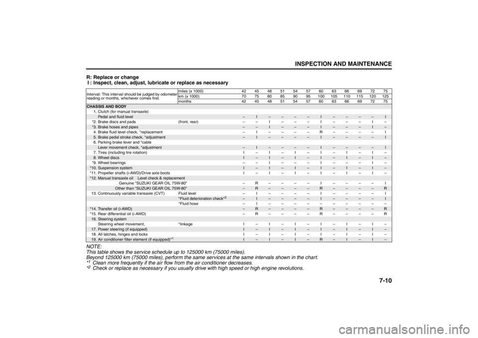
R: Replace or changeI : Inspect, clean, adjust, lubr icate or replace as necessary
NOTE:
This table shows the service schedule up to 125000 km (75000 miles).
Beyond 125000 km (75000 miles), perform the same services at the same intervals shown in the chart.
*1Clean more frequently if the air flow from the air conditioner decreases.
*2Check or replace as necessary if you usually drive with high speed or high engine revolutions.
Interval: This interval should be judged by odometer
reading or months, whichever comes first. miles (x 1000) 42 45 48 51 54 57 60 63 66 69 72 75
km (x 1000) 70 75 80 85 90 95 100 105 110 115 120 125
months 42 45 48 51 54 57 60 63 66 69 72 75CHASSIS AND BODY
1. Clutch (for manual transaxle)
Pedal and fluid level
–
I
–
–
–
–
I
–
–
–
–
I
*2. Brake discs and pads (front, rear) – – I – – – I – – – I –
*3.
Brake hoses and pipes
–
–
I
–
–
–
I
–
–
–
I
–
4.Brake fluid level check, *replacement – I ––––R–––– I
5.Brake pedal stroke check, *adjustment
–
I
–
–
–
–
I
–
–
–
–
I
6. Parking brake lever and *cable
Lever movement check, *adjustment
–
I
–
–
–
–
I
–
–
–
–
I
7. Tires (including tire rotation) I – I – I – I – I – I –
8.Wheel discs
I
–
I
–
I
–
I
–
I
–
I
–
*9. Wheel bearings – – I – – – I – – – I –
*10.
Suspension system
I
–
I
–
I
–
I
–
I
–
I
–
*11. Propeller shafts (i-AWD)/Drive axle boots I – I – I – I – I – I –
*12.
Manual transaxle oil Level check & replacement
Genuine “SUZUKI GEAR OIL 75W-80” –R–––– I –––– IOther than “SUZUKI GEAR OIL 75W-80”
–
R
–
–
–
–
R
–
–
–
–
R
13. Continuously variable transaxle (CVT) Fluid level – I –––– I –––– I
*Fluid deterioration check*
2
–
I
–
–
–
–
I
–
–
–
–
I
*Fluid hose – I ––––––––––
*14.
Transfer oil (i-AWD)
–
R
–
–
–
–
R
–
–
–
–
R
*15.Rear differential oil (i-AWD) –R––––R––––R
16.
Steering systemSteering wheel movement, *linkage I – I – I – I – I – I –
17.
Power steering (if equipped)
I
–
I
–
I
–
I
–
I
–
I
–
18. All latches, hinges and locks I – I – I – I – I – I –
19.
Air conditioner filter element (if equipped)*
1
I
–
I
–
I
–
R
–
I
–
I
–
Page 299 of 388
7-14
INSPECTION AND MAINTENANCE
57L20-03E
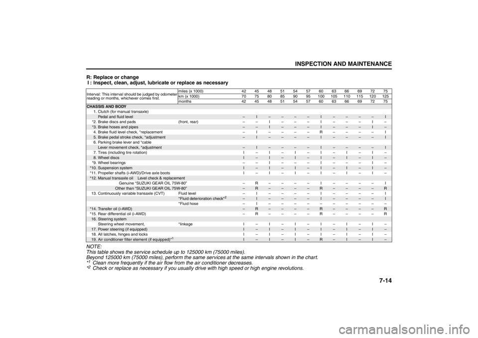
R: Replace or changeI : Inspect, clean, adjust, lubr icate or replace as necessary
NOTE:
This table shows the service schedule up to 125000 km (75000 miles).
Beyond 125000 km (75000 miles), perform the same services at the same intervals shown in the chart.
*1Clean more frequently if the air flow from the air conditioner decreases.
*2Check or replace as necessary if you usually drive with high speed or high engine revolutions.
Interval: This interval should be judged by odometer
reading or months, whichever comes first. miles (x 1000) 42 45 48 51 54 57 60 63 66 69 72 75
km (x 1000) 70 75 80 85 90 95 100 105 110 115 120 125
months 42 45 48 51 54 57 60 63 66 69 72 75CHASSIS AND BODY
1. Clutch (for manual transaxle)
Pedal and fluid level
–
I
–
–
–
–
I
–
–
–
–
I
*2. Brake discs and pads (front, rear) – – I – – – I – – – I –
*3.
Brake hoses and pipes
–
–
I
–
–
–
I
–
–
–
I
–
4.Brake fluid level check, *replacement – I ––––R–––– I
5.Brake pedal stroke check, *adjustment
–
I
–
–
–
–
I
–
–
–
–
I
6. Parking brake lever and *cable
Lever movement check, *adjustment
–
I
–
–
–
–
I
–
–
–
–
I
7. Tires (including tire rotation) I – I – I – I – I – I –
8.Wheel discs
I
–
I
–
I
–
I
–
I
–
I
–
*9. Wheel bearings – – I – – – I – – – I –
*10.
Suspension system
I
–
I
–
I
–
I
–
I
–
I
–
*11. Propeller shafts (i-AWD)/Drive axle boots I – I – I – I – I – I –
*12.
Manual transaxle oil Level check & replacement
Genuine “SUZUKI GEAR OIL 75W-80” –R–––– I –––– IOther than “SUZUKI GEAR OIL 75W-80”
–
R
–
–
–
–
R
–
–
–
–
R
13. Continuously variable transaxle (CVT) Fluid level – I –––– I –––– I
*Fluid deterioration check*
2
–
I
–
–
–
–
I
–
–
–
–
I
*Fluid hose – I ––––––––––
*14.
Transfer oil (i-AWD)
–
R
–
–
–
–
R
–
–
–
–
R
*15.Rear differential oil (i-AWD) –R––––R––––R
16.
Steering systemSteering wheel movement, *linkage I – I – I – I – I – I –
17.
Power steering (if equipped)
I
–
I
–
I
–
I
–
I
–
I
–
18. All latches, hinges and locks I – I – I – I – I – I –
19.
Air conditioner filter element (if equipped)*
1
I
–
I
–
I
–
R
–
I
–
I
–
Page 313 of 388
7-28
INSPECTION AND MAINTENANCE
57L20-03E
TiresFor safe operation of your vehicle, it is
important that the tires be the correct
type and size, in good condition, and
properly inflated. Be sure to follow the
requirements and recommendations in
this section.
Tire Sidewall Labeling
Useful information about a tire is
molded into its sidewall. The example
below shows a typical passenger car
tire.
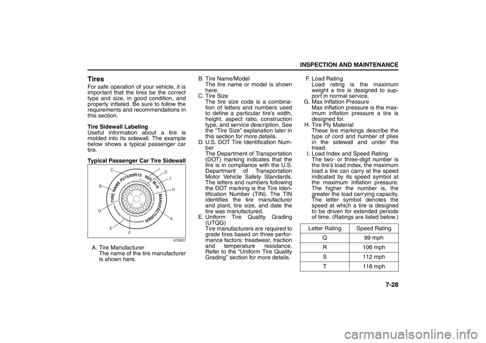
Typical Passenger Car Tire Sidewall
67D027
A. Tire Manufacturer
The name of the tire manufacturer
is shown here.B. Tire Name/Model
The tire name or model is shown
here.
C. Tire Size
The tire size code is a combina-
tion of letters and numbers used
to define a particular tire’s width,
height, aspect ratio, construction
type, and service description. See
the “Tire Size” explanation later in
this section for more details.
D. U.S. DOT Tire Identification Num-
ber
The Department of Transportation
(DOT) marking indicates that the
tire is in compliance with the U.S.
Department of Transportation
Motor Vehicle Safety Standards.
The letters and numbers following
the DOT marking is the Tire Iden-
tification Number (TIN). The TIN
identifies the tire manufacturer
and plant, tire size, and date the
tire was manufactured.
E. Uniform Tire Quality Grading
(UTQG)
Tire manufacturers are required to
grade tires based on three perfor-
mance factors: treadwear, traction
and temperature resistance.
Refer to the “Uniform Tire Quality
Grading” section for more details.F. Load Rating
Load rating is the maximum
weight a tire is designed to sup-
port in normal service.
G. Max Inflation Pressure
Max inflation pressure is the max-
imum inflation pressure a tire is
designed for.
H. Tire Ply Material
These tire markings describe the
type of cord and number of plies
in the sidewall and under the
tread.
I. Load Index and Speed Rating
The two- or three-digit number is
the tire’s load index, the maximum
load a tire can carry at the speed
indicated by its speed symbol at
the maximum inflation pressure.
The higher the number is, the
greater the load carrying capacity.
The letter symbol denotes the
speed at which a tire is designed
to be driven for extended periods
of time. (Ratings are listed below.)
AH B
G
E
FD
J I
C
Letter Rating Speed Rating
Q99 mph
R 106 mph
S 112 mph
T 118 mph
Page 316 of 388
7-31INSPECTION AND MAINTENANCE
57L20-03E
Measuring Air Pressure
Use the following steps to achieve
proper tire inflation:
1) Identify the recommended tire pres-
sure on the vehicle’s Tire and Load-
ing Information Label or in the
owner’s manual.
2) Remove the valve cap from the tire
valve stem.
3) Using a reliable pressure gauge,
measure the tire inflation pressure
by pressing the tire gauge firmly
onto the valve to get a pressure
measurement. Remember that
inflation pressures should be
checked when the tires are “cold”,
meaning before they have been
driven one mile or after sitting for
three hours or more allowing the
tire to cool to ambient air tempera-
ture.
4) If the air pressure is too high, slowly
release the air by pressing on the
tire valve stem with the edge of the
tire gauge until you reach the cor-
rect pressure.
5) If the air pressure is too low, fill the
tire with air at a service station until
it reaches the recommended pres-
sure.
6) Make sure all tires have the same
air pressure (unless the owner’s
manual indicates otherwise).Tire Inspection
Inspect your vehicle’s tires at least
once a month by performing the fol-
lowing checks:
1) Measure the air pressure with a tire
gauge. Adjust the pressure if nec-
essary. Remember to check the
spare tire, too. Refer to the “Mea-
suring Air Pressure” section.
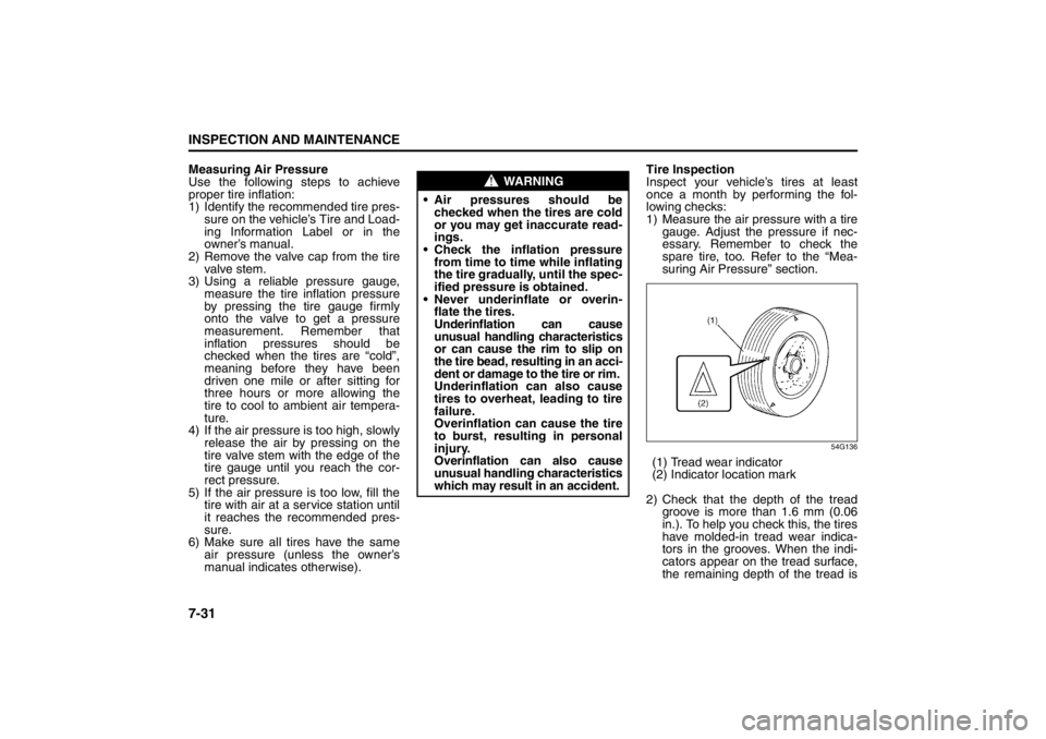
54G136
(1) Tread wear indicator
(2) Indicator location mark
2) Check that the depth of the tread
groove is more than 1.6 mm (0.06
in.). To help you check this, the tires
have molded-in tread wear indica-
tors in the grooves. When the indi-
cators appear on the tread surface,
the remaining depth of the tread is
WARNING
Air pressures should be
checked when the tires are cold
or you may get inaccurate read-
ings.
Check the inflation pressure
from time to time while inflating
the tire gradually, until the spec-
ified pressure is obtained.
Never underinflate or overin-
flate the tires.
Underinflation can cause
unusual handling characteristics
or can cause the rim to slip on
the tire bead, resulting in an acci-
dent or damage to the tire or rim.
Underinflation can also cause
tires to overheat, leading to tire
failure.
Overinflation can cause the tire
to burst, resulting in personal
injury.
Overinflation can also cause
unusual handling characteristics
which may result in an accident.
Page 318 of 388
7-33INSPECTION AND MAINTENANCE
57L20-03E
Uniform Tire Quality Grading
The U.S. National Highway Traffic
Safety Administration has developed a
grading system for evaluating the per-
formance of passenger car tires. The
following information will help you
understand the grading system, which
applies to vehicles sold in the U.S.
Consult your SUZUKI dealer or tire
retailer for help in choosing the correct
replacement tires for your vehicle.
Quality grades can be found where
applicable on the tire sidewall between
tread shoulder and maximum section
width. For example:
Treadwear 200 Traction AA Tempera-
ture A
DOT Quality Grades
Treadwear
Traction AA A B C
Temperature A B C
All Passenger Car Tires Must Conform
To Federal Safety Requirements in
Addition To These GradesTreadwear
The treadwear grade is a comparative
rating based on the wear rate of the tire
when tested under controlled condi-
tions on a specified government test
course. For example, a tire graded 150
would wear one and one-half (1 1/2)
times as well on the government course
as a tire graded 100. The relative per-
formance of tires depends upon the
actual conditions of their use, however
and may depart significantly from the
norm due to variations in driving habits,
service practices and differences in
road characteristics and climate.
Traction – AA, A, B, C
The traction grades, from highest to
lowest, are AA, A, B and C. Those
grades represent the tire’s ability to
stop on wet pavement as measured
under controlled conditions on speci-
fied government test surfaces of
asphalt and concrete. A tire marked C
may have poor traction performance.Temperature – A, B, C
The temperature grades are A (the
highest), B and C, representing the
tire’s resistance to the generation of
heat and its ability to dissipate heat
when tested under controlled condi-
tions on a specified indoor laboratory
test wheel. Sustained high tempera-
ture can cause the material of the tire
to degenerate and reduce tire life, and
excessive temperature can lead to
sudden tire failure. The grade C corre-
sponds to a level of performance
which all passenger car tires must
meet under the Federal Motor Vehicle
Safety Standard No. 109. Grades B
and A represent higher levels of per-
formance on the laboratory test wheel
than the minimum required by law.
WARNING
The traction grade assigned to
this tire is based on straight-
ahead braking traction tests, and
does not include acceleration,
cornering, hydroplaning or peak
traction characteristics.
WARNING
The temperature grade for this
tire is established for a tire that is
properly inflated and not over-
loaded. Excessive speed, under-
inflation or excessive loading,
either separately or in combina-
tion, can cause heat buildup and
possible tire failure.
Page 321 of 388

7-36
INSPECTION AND MAINTENANCE
57L20-03E
GLOSSARY OF TIRE TERMINOL-
OGY
Accessory Weight – the combined
weight (in excess of those standard
items which may be replaced) of CVT,
power steering, power brakes, power
windows, power seats, radio, and
heater, to the extent that these items
are available as factory-installed
equipment (whether installed or not).
Cold Tire Inflation Pressure – the pres-
sure in a tire that has been driven less
than 1 mile or has been standing for
three hours or more.
Curb Weight – the weight of a motor
vehicle with standard equipment
including the maximum capacity of
fuel, oil, and coolant, and, if so
equipped, air conditioning and addi-
tional weight optional engine.
Intended Outboard Sidewall – (1) the
sidewall that contains a whitewall,
bears white lettering or bears manu-
facturer, brand, and/or model name
molding that is higher or deeper than
the same molding on the other side-
wall of the tire, or (2) the outward fac-
ing sidewall of an asymmetrical tire
that has a particular side that must
always face outward when mounted
on a vehicle.Maximum Inflation Pressure – the max-
imum cold inflation pressure a tire is
designed to support in normal service.
Maximum Loaded Vehicle Weight –
the sum of curb weight, accessory
weight, vehicle capacity weight (total
load capacity), and production options
weight.
Normal Occupant Weight – 68 kilo-
grams times the number of occupants
specified in the second column of
Table 1 (shown below).
Occupant distribution – distribution of
occupants in a vehicle as specified in
the third column of Table 1 (shown
below).
Production Options Weight – the com-
bined weight of those installed regular
production options weighing over 2.3
kilograms in excess of those standard
items which they replace, not previ-
ously considered in curb weight or
accessory weight, including heavy
duty brakes, ride levelers, roof rack,
heavy duty battery, and special trim.
Recommended Inflation Pressure –
the cold tire inflation pressure recom-
mended by a manufacturer.
Rim – metal support for a tire or tire
and tube assembly upon which the tire
beads are seated.Vehicle Capacity Weight – the rated
cargo and luggage load plus 68 kilo-
grams (150 lbs) times the vehicle’s
designated seating capacity.
Vehicle Maximum Load on the Tire –
the load on an individual tire that is
determined by distributing to each axle
its share of the maximum loaded vehi-
cle weight and dividing by two.
Vehicle Normal Load on the Tire – the
load on an individual tire that is deter-
mined by distributing to each axle its
share of the curb weight, accessory
weight, and normal occupant weight
(distributed in accordance with Table 1
shown below) and dividing by 2.
TABLE 1 – Occupant Loading and
Distribution For Vehicle Normal
Load For Various Designated Seat-
ing Capacities
Designated
seating
capacity,
number of
occupantsVehicle nor-
mal load,
number of
occupants
Occupant
distribution
in a nor-
mally loaded
vehicle
2 through 4 2 2 in front5 through 10
32 in front,
1 in second
seat