parking brake SUZUKI KIZASHI 2010 1.G Owner's Guide
[x] Cancel search | Manufacturer: SUZUKI, Model Year: 2010, Model line: KIZASHI, Model: SUZUKI KIZASHI 2010 1.GPages: 388, PDF Size: 4.94 MB
Page 310 of 388
7-25INSPECTION AND MAINTENANCE
57L20-03E
6) The handle of the CVT fluid dipstick is
colored red or orange for easy identifi-
cation.
Remove the dipstick, clean it and push
it back in until the cap seats. Pull out
the dipstick and read the fluid level.
The fluid level should be between the
two marks in the “HOT” range on the
dipstick.
7) Add just enough specified fluid through
the dipstick hole to fill the transaxle to
the proper level. It takes only 0.6 liters
(1.27 US pt) for CVT to raise the level
from “LOW” to “FULL”.Deterioration Checking or Chang-
ing FluidSince special procedures, materials and
tools are required to check the deteriora-
tion of CVT fluid or change, it is recom-
mended that you trust this job to your
authorized SUZUKI dealer.
BrakesBrake Fluid
57L71010
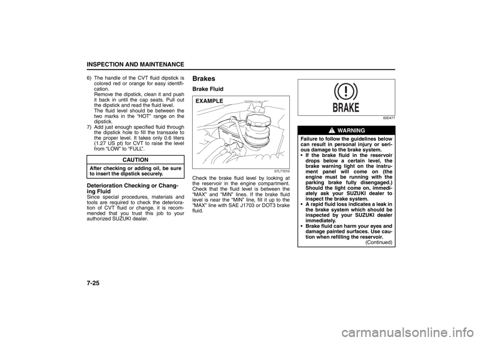
Check the brake fluid level by looking at
the reservoir in the engine compartment.
Check that the fluid level is between the
“MAX” and “MIN” lines. If the brake fluid
level is near the “MIN” line, fill it up to the
“MAX” line with SAE J1703 or DOT3 brake
fluid.
65D477
CAUTION
After checking or adding oil, be sure
to insert the dipstick securely.
EXAMPLE
WARNING
Failure to follow the guidelines below
can result in personal injury or seri-
ous damage to the brake system.
If the brake fluid in the reservoir
drops below a certain level, the
brake warning light on the instru-
ment panel will come on (the
engine must be running with the
parking brake fully disengaged.)
Should the light come on, immedi-
ately ask your SUZUKI dealer to
inspect the brake system.
A rapid fluid loss indicates a leak in
the brake system which should be
inspected by your SUZUKI dealer
immediately.
Brake fluid can harm your eyes and
damage painted surfaces. Use cau-
tion when refilling the reservoir.
(Continued)
Page 311 of 388

7-26
INSPECTION AND MAINTENANCE
57L20-03E
NOTE:
With disc brakes, the fluid level can be
expected to gradually fall as the brake
pads wear.Brake Pedal
65D345
With the engine running and the parking
brake set, measure the distance between
the brake pedal and floor carpet when the
pedal is depressed with approximately 300
N (66 lbs, 30 kg) of force. The minimum
distance required is as specified. Since
your vehicle’s brake system is self-adjust-
ing, there is no need for pedal adjustment.
If the pedal to floor carpet distance asmeasured above is less than the minimum
distance required, have your vehicle
inspected by your SUZUKI dealer.
NOTE:
When measuring the distance between the
brake pedal and floor wall, be sure not to
include the floor mat or rubber on the floor
wall in your measurement.
60G104
WARNING
(Continued)
Do not use any fluid other than SAE
J1703 or DOT3 brake fluid. Do not
use reclaimed fluid or fluid that has
been stored in old or open contain-
ers. It is essential that foreign parti-
cles and other liquids are kept out
of the brake fluid reservoir.
WARNING
Brake fluid is harmful or fatal if swal-
lowed, and harmful if it comes in con-
tact with skin or eyes. If swallowed,
do not induce vomiting. Immediately
contact a poison control center or a
physician. If brake fluid gets in eyes,
flush eyes with water and seek medi-
cal attention. Wash thoroughly after
handling. Solution can be poisonous
to animals. Keep out of the reach of
children and animals.
CAUTION
The brake fluid should be replaced
according to the maintenance sched-
ule. Have the brake fluid replaced by
your SUZUKI dealer.
Pedal to floor carpet minimum distance
“a”
73 mm (2.9 in.)
“a”
Floor carpet
Page 312 of 388
7-27INSPECTION AND MAINTENANCE
57L20-03E
Parking Brake Lever
60A226
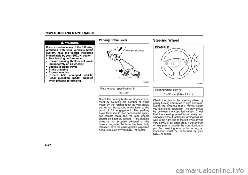
Check the parking brake for proper adjust-
ment by counting the number of clicks
made by the ratchet teeth as you slowly
pull up on the parking brake lever to the
point of full engagement. The parking
brake lever should stop between the speci-
fied ratchet teeth and the rear wheels
should be securely locked. If the parking
brake is not properly adjusted or the
brakes drag after the lever has been fully
released, have the parking brake inspected
and/or adjusted by your SUZUKI dealer.
Steering Wheel
80J005
Check the play of the steering wheel by
gently turning it from left to right and mea-
suring the distance that it moves before
you feel slight resistance. The play should
be between the specified values. Check
that the steering wheel turns easily and
smoothly without rattling by turning it all the
way to the right and to the left while driving
very slowly in an open area. If the amount
of free play is outside the specification or
you find anything else to be wrong, an
inspection must be performed by your
SUZUKI dealer.
WARNING
If you experience any of the following
problems with your vehicle’s brake
system, have the vehicle inspected
immediately by your SUZUKI dealer.
Poor braking performance
Uneven braking (brakes not work-
ing uniformly on all wheels.)
Excessive pedal travel
Brake dragging
Excessive noise
(Except ABS equipped vehicle)
Pedal pulsation (pedal pulsates
when pressed for braking.)
Ratchet tooth specification “b”
6th – 8th
200 N (44 lbs, 20 kg)
“b”
Steering wheel play “c”
0 – 30 mm (0.0 – 1.2 in.)
“c”
EXAMPLE
Page 345 of 388

8-2
EMERGENCY SERVICE
57L20-03E
Jacking Instructions
75F062
1) Place the vehicle on level, hard ground.
2) Set the parking brake firmly and shift
into “P” (Park) if your vehicle has a CVT,
or shift into “R” (Reverse) if your vehicle
has a manual transaxle.
3) Turn on the hazard warning flasher if
your vehicle is near traffic.4) Block the front and rear of the wheel
diagonally opposite of the wheel being
lifted.
5) Place the spare wheel near the wheel
being lifted as shown in the illustration
in case that the jack slips.
57L7004779K058
(1) Jacking point
6) Position the jack as shown in the illus-
tration and raise the jack by turning the
jack-head groove fits around the jacking
point beneath the vehicle body.
WARNING
Be sure to shift into “P” (Park) for a
CVT vehicle, or into “R” (Reverse)
for a manual transaxle vehicle
when you jack up the vehicle.
Never jack up the vehicle with the
transaxle in “N” (Neutral). Other-
wise, an unstable jack may cause
an accident.
(1)
(1)
(1)
Trailer Towing: 5, 11, 13
Towing Your Vehicle (recreational towing): 13
Page 349 of 388
8-6
EMERGENCY SERVICE
57L20-03E
Jump Starting Instructions
When jump starting your vehicle, use
the following procedure:
60A269
1) Use only a 12-volt battery to jump startyour vehicle. Position the good 12-volt
battery close to your vehicle so that the
jumper cables will reach both batteries.
When using a battery installed on
another vehicle, DO NOT LET THE
VEHICLES TOUCH. Set the parking
brakes fully on both vehicles. 2) Turn off all vehicle accessories, except
those necessary for safety reasons (for
example, headlights or hazard lights).
57L81004
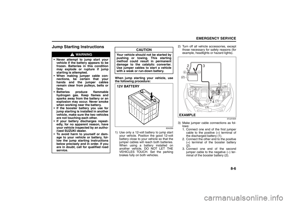
3) Make jumper cable connections as fol-lows:
1. Connect one end of the first jumper
cable to the positive (+) terminal of
the discharged battery (1).
2. Connect the other end to the positive (+) terminal of the booster battery
(2).
3. Connect one end of the second
jumper cable to the negative (–) ter-
minal of the booster battery (2).
WARNING
• Never attempt to jump start yourvehicle if the battery appears to be
frozen. Batteries in this condition
may explode or rupture if jump
starting is attempted.
When making jumper cable con- nections, be certain that your
hands and the jumper cables
remain clear from pulleys, belts or
fans.
Batteries produce flammable
hydrogen gas. Keep flames and
sparks away from the battery or an
explosion may occur. Never smoke
when working near the battery.
If the booster battery you use for jump starting is installed in another
vehicle, make sure the two vehicles
are not touching each other.
If your battery discharges repeat- edly, for no apparent reason, have
your vehicle inspected by an autho-
rized SUZUKI dealer.
To avoid harm to yourself or dam- age to your vehicle or battery, fol-
low the jump starting instructions
below precisely and in order. If you
are in doubt, call for qualified road
service.
CAUTION
Your vehicle should not be started by
pushing or towing. This starting
method could result in permanent
damage to the catalytic converter.
Use jumper cables to start a vehicle
with a weak or run-down battery.12V BATTERY
(3)
(2)
(1)
1
4
23
EXAMPLE
Page 379 of 388
12-3
SPECIFICATIONS
57L20-03E
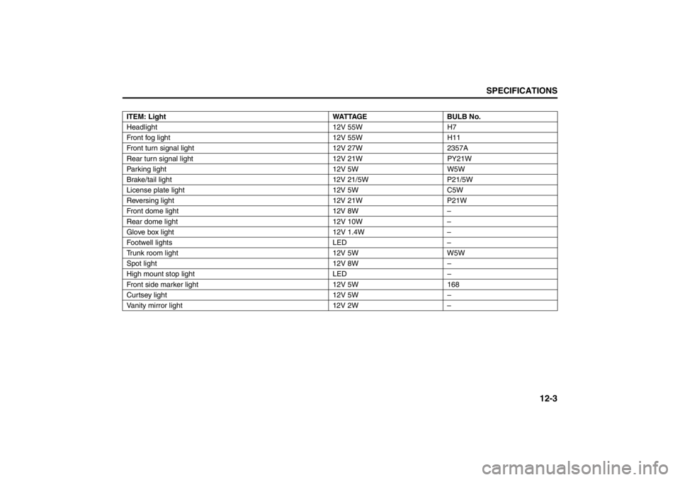
ITEM: Light WATTAGE BULB No.
Headlight 12V 55W H7
Front fog light 12V 55W H11
Front turn signal light 12V 27W 2357A
Rear turn signal light 12V 21W PY21W
Parking light 12V 5W W5W
Brake/tail light 12V 21/5W P21/5W
License plate light 12V 5W C5W
Reversing light 12V 21W P21W
Front dome light 12V 8W –
Rear dome light 12V 10W –
Glove box light 12V 1.4W –
Footwell lights LED –
Trunk room light 12V 5W W5W
Spot light 12V 8W –
High mount stop light LED –
Front side marker light 12V 5W 168
Curtsey light 12V 5W –
Vanity mirror light 12V 2W –
Specifications: 1, 2, 5, 6, 7, 10, 11
Page 384 of 388

13-4INDEX
57L20-03E
NNet/Rope Hooks ................................................................... 5-92OOdometer .............................................................................. 2-84
Oil Level Check .................................................................... 7-15
Oil Pressure Light ................................................................ 2-72
On-Board Vehicle Computers and Event Data
Recorders ............................................................................. 10-3
Open Door Warning Light ................................................... 2-75
Outside Rearview Mirrors ................................................... 2-22
Overhead Console ............................................................... 5-86PParking Brake Lever ................................................... 3-10, 7-27
Parking Sensors .................................................................. 3-23
Pedals ................................................................................... 3-11
Periodic Maintenance Schedule ........................................... 7-3
Power Door Locking System ................................................ 2-4
Power Mirror Control ........................................................... 2-22
Power Window Controls ..................................................... 2-17
Power-Assisted Brakes ....................................................... 3-28RRadio Antenna ....................................................................... 5-9
Rain-sensing Wipers ......................................................... 2-108
Rain-sensing Wipers and Washer Lever ......................... 2-107
Rear Center Seat Belt .......................................................... 2-38
Rear Seats ............................................................................ 2-29
Refill with Oil and Check for Leaks .................................... 7-18
Refilling................................................................................. 7-16
Replace the Oil Filter ........................................................... 7-17
Replacing Tires and/or Wheels .......................................... 3-38
Reporting Safety Defects .................................................... 10-4 Roof Rack Anchors .............................................................. 5-92
SSafety Certification Label .................................................... 10-2
Seat Belt Extender ............................................................... 2-53
Seat Belt Inspection ............................................................. 2-43
Seat Belt Pretensioner System ........................................... 2-54
Seat Belt Reminder .............................................................. 2-40
Seat Belts and Child Restraint Systems ............................ 2-34
Seat Position Memory System ............................................ 2-26
Selection of Coolant ............................................................ 7-18
Selection of Power Supply Modes........................................ 3-4
Setting Mode......................................................................... 2-85
Shoulder Anchor Height Adjuster ...................................... 2-43
Side Air Bags and Side Curtain Air Bags .......................... 2-59
Side Door Locks ..................................................................... 2-3
Snow Tires ............................................................................ 7-35
Spark Plugs .......................................................................... 7-20
SPECIFICATIONS .......
.......................................................... 12-1
Specified Fluid...................................................................... 7-24
Specified Gear Oil ................................................................ 7-22
Specified Oil ......................................................................... 7-15
Speedometer ........................................................................ 2-78
Spot Light ............................................................................. 5-80
Stability Control System...................................................... 3-31
Starting the Engine ................................................................ 3-7
Steering Wheel ..................................................................... 7-27
Sun Visor .............................................................................. 5-77
Sunroof ................................................................................. 5-83
Supplemental Restraint System (a ir bags) ........................ 2-55TTachometer ........................................................................... 2-78