Air conditioning SUZUKI KIZASHI 2010 1.G Owners Manual
[x] Cancel search | Manufacturer: SUZUKI, Model Year: 2010, Model line: KIZASHI, Model: SUZUKI KIZASHI 2010 1.GPages: 388, PDF Size: 4.94 MB
Page 12 of 388

ILLUSTRATED TABLE OF CONTENTS
57L20-03E
INSTRUMENT PANEL1. Power Window Controls (P.2-17)/Lock switch (P.2-18)
2. Power Mirror Control (P.2-22)
3. Remote Audio Controls (P.5-64)
4. Front Air Bags (P.2-57)
5. Cruise Control Switch (if equipped) (P.3-21)
6. Audio (P.5-10)
7. Heating and Air Conditioning System (P.5-1)
8. Fuse Box (P.7-40)
9. Information display switches (P.2-80)
10. Parking Brake Lever (P.3-10)
11. Center Console Box (P.5-89)/ Accessory Socket (P.5-80)
12. Glove Box (P.5-85)
57L1F005
9
8
10 12
11
8
1
1
7
4
4
3
5
6
2
Page 104 of 388
2-85BEFORE DRIVING
57L20-03E
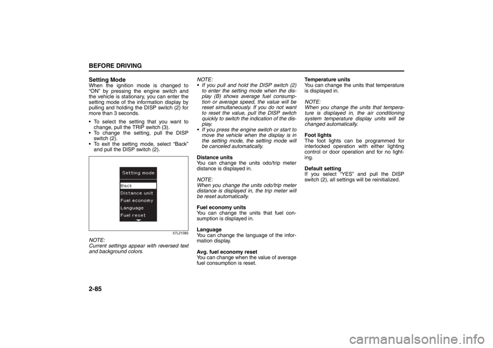
Setting ModeWhen the ignition mode is changed to
“ON” by pressing the engine switch and
the vehicle is stationary, you can enter the
setting mode of the information display by
pulling and holding the DISP switch (2) for
more than 3 seconds.
To select the setting that you want to
change, pull the TRIP switch (3).
To change the setting, pull the DISP
switch (2).
To exit the setting mode, select “Back”
and pull the DISP switch (2).
57L21085
NOTE:
Current settings appear with reversed text
and background colors.NOTE:
If you pull and hold the DISP switch (2)
to enter the setting mode when the dis-
play (B) shows average fuel consump-
tion or average speed, the value will be
reset simultaneously. If you do not want
to reset the value, pull the DISP switch
quickly to switch the indication of the dis-
play.
If you press the engine switch or start to
move the vehicle when the display is in
the setting mode, the setting mode will
be canceled automatically.
Distance units
You can change the units odo/trip meter
distance is displayed in.
NOTE:
When you change the units odo/trip meter
distance is displayed in, the trip meter will
be reset automatically.
Fuel economy units
You can change the units that fuel con-
sumption is displayed in.
Language
You can change the language of the infor-
mation display.
Avg. fuel economy reset
You can change when the value of average
fuel consumption is reset.Temperature units
You can change the units that temperature
is displayed in.
NOTE:
When you change the units that tempera-
ture is displayed in, the air conditioning
system temperature display units will be
changed automatically.
Foot lights
The foot lights can be programmed for
interlocked operation with either lighting
control or door operation and for no light-
ing.
Default setting
If you select “YES” and pull the DISP
switch (2), all settings will be reinitialized.
Page 132 of 388
3-1OPERATING YOUR VEHICLE
57L20-03E
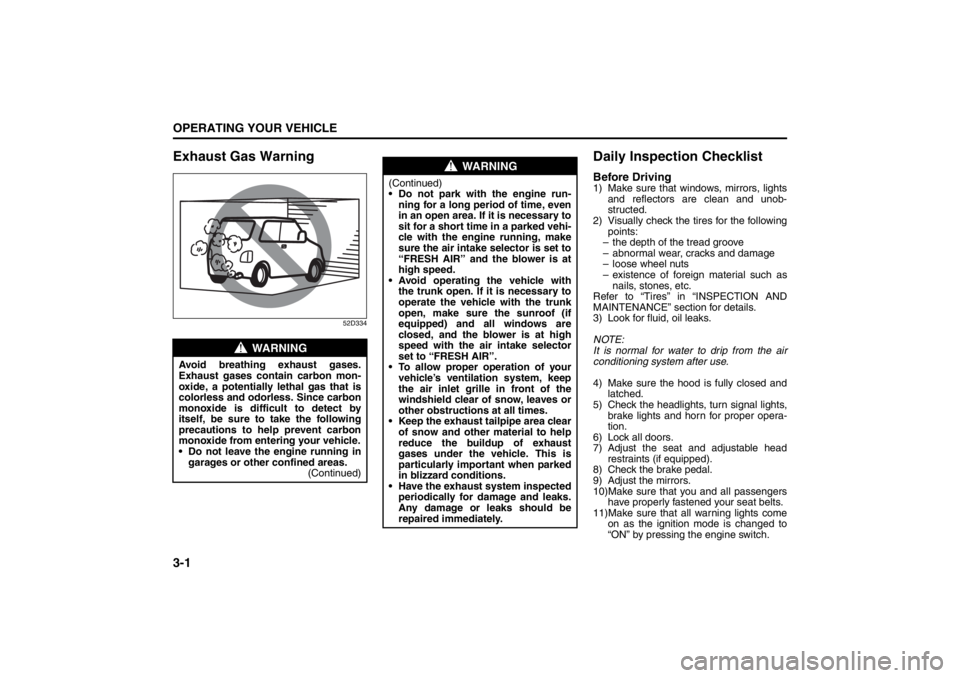
Exhaust Gas Warning
52D334
Daily Inspection ChecklistBefore Driving1) Make sure that windows, mirrors, lights
and reflectors are clean and unob-
structed.
2) Visually check the tires for the following
points:
– the depth of the tread groove
– abnormal wear, cracks and damage
– loose wheel nuts
– existence of foreign material such as
nails, stones, etc.
Refer to “Tires” in “INSPECTION AND
MAINTENANCE” section for details.
3) Look for fluid, oil leaks.
NOTE:
It is normal for water to drip from the air
conditioning system after use.
4) Make sure the hood is fully closed and
latched.
5) Check the headlights, turn signal lights,
brake lights and horn for proper opera-
tion.
6) Lock all doors.
7) Adjust the seat and adjustable head
restraints (if equipped).
8) Check the brake pedal.
9) Adjust the mirrors.
10)Make sure that you and all passengers
have properly fastened your seat belts.
11)Make sure that all warning lights come
on as the ignition mode is changed to
“ON” by pressing the engine switch.
WARNING
Avoid breathing exhaust gases.
Exhaust gases contain carbon mon-
oxide, a potentially lethal gas that is
colorless and odorless. Since carbon
monoxide is difficult to detect by
itself, be sure to take the following
precautions to help prevent carbon
monoxide from entering your vehicle.
Do not leave the engine running in
garages or other confined areas.
(Continued)
WARNING
(Continued)
Do not park with the engine run-
ning for a long period of time, even
in an open area. If it is necessary to
sit for a short time in a parked vehi-
cle with the engine running, make
sure the air intake selector is set to
“FRESH AIR” and the blower is at
high speed.
Avoid operating the vehicle with
the trunk open. If it is necessary to
operate the vehicle with the trunk
open, make sure the sunroof (if
equipped) and all windows are
closed, and the blower is at high
speed with the air intake selector
set to “FRESH AIR”.
To allow proper operation of your
vehicle’s ventilation system, keep
the air inlet grille in front of the
windshield clear of snow, leaves or
other obstructions at all times.
Keep the exhaust tailpipe area clear
of snow and other material to help
reduce the buildup of exhaust
gases under the vehicle. This is
particularly important when parked
in blizzard conditions.
Have the exhaust system inspected
periodically for damage and leaks.
Any damage or leaks should be
repaired immediately.
Ignition Switch: 8
Page 139 of 388
3-8
OPERATING YOUR VEHICLE
57L20-03E
You should turn off such loads as theheadlights and air conditioning system to
facilitate starting of the engine.
Even if you fail to start the engine, the
starter motor will stop turning automati-
cally after a short time. After the starter
motor has stopped or if there is some
problem with the system, the starter
motor will rotate only while the engine
switch is being pressed.Stopping the engine Depress the engine switch to stop theengine after the vehicle stopped com-
pletely.
In case of emergency, you can stop the engine by depressing the engine switch
more than 3 seconds while the vehicle in
motion.
NOTE:
Except in emergency, do not stop the
engine while the vehicle in motion.
The steering and braking operation will
require more effort s when the engine
stopped.
Refer to “Braking” in the “OPERATING
YOUR VEHICLE” section.
Starting a Cold EngineWith your foot off the accelerator pedal,
crank the engine by pressing the engine
switch to change the ignition mode to
“START”.
After pressing the engine switch to change
the ignition mode to “START”, the starter
cranks the engine for about 12 seconds
before it can start the engine. If the engine
fails to start at the first attempt, wait about
15 seconds, then try again while keeping
the engine switch pressed while pressing
down the accelerator pedal to 1/3 of its
travel. Release the accelerator pedal when
the engine starts.
If the engine still does not start, try holding
the accelerator pedal all the way to the
floor while cranking. Th is should clear the
engine if it is flooded.
If you are unable to start the engine using
this procedure, consult your SUZUKI
dealer.
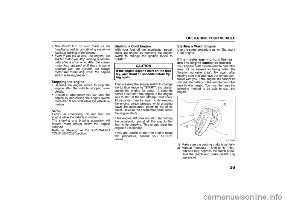
Starting a Warm EngineUse the same procedure as for “Starting a
Cold Engine”.If the master warning light flashes
and the engine cannot be startedYour keyless start system remote controller
may not be sensed as being within the
“interior workable area”. Try again after
making sure that you have the remote con-
troller with you. If the engine still cannot be
started, the battery of the remote controller
may be discharged. You must then use the
following method to be able to start the
engine.
57L21124
1) Make sure the parking brake is set fully.
2) Manual Transaxle – Shift to “N” (Neu- tral) and fully depress the clutch pedal.
Hold the clutch and brake pedals fully
depressed.
CAUTION
If the engine doesn’ t start on the first
try, wait about 15 seconds before try-
ing again.
(1)
(2)
Cruise Control: 7, 8
Remote Audio Controls:
Horn: 6
Page 179 of 388
OTHER CONTROLS AND EQUIPMENT
5
57L20-03E
60G407
OTHER CONTROLS AND EQUIPMENTAutomatic Heating and Air Conditioning System
(Climate Control) ................................................................. 5-1
Radio Antenna ..................................................................... 5-9
Audio Systems .................................................................... 5-10
Fuel Filler Door .................................................................... 5-73
Fuel Filler Cap ..................................................................... 5-74
Engine Hood ........................................................................ 5-75
Sun Visor ............................................................................. 5-77
Interior Light Switch ........................................................... 5-78
Courtesy Lights ................................................................... 5-79
Footwell Lights .................................................................... 5-79
Trunk Light .......................................................................... 5-79
Spot Light ............................................................................ 5-80
Accessory Socket ............................................................... 5-80
Assist Grips ......................................................................... 5-82
Coat Hooks .......................................................................... 5-83
Sunroof (if equipped) .......................................................... 5-83
Glove Box ............................................................................ 5-85
Overhead Console .............................................................. 5-86
Lidded Instrument Panel Box ............................................ 5-87
Cup Holder and Storage Area (if equipped) ..................... 5-87
Front Seat Back Pocket (if equipped) ............................... 5-89
Footrest ................................................................................ 5-89
Center Console Box ............................................................ 5-89
Armrest ................................................................................ 5-90
Floor Mats (if equipped) ..................................................... 5-91
Luggage Under-box ............................................................ 5-92
Net/Rope Hooks .................................................................. 5-92
Roof Rack Anchors (if equipped) ...................................... 5-92
HomeLink
® (if equipped) .................................................... 5-93
Frame Hooks ....................................................................... 5-96
Page 180 of 388

5-1OTHER CONTROLS AND EQUIPMENT
57L20-03E
Automatic Heating and Air Conditioning System
(Climate Control)Air Outlet
57L51001
(6) (6)(5)
(5)
(7)
(3)
(2) (3)(2)(1)
(4)
EXAMPLE
(1) Windshield defroster outlet
(2) Side defroster outlet
(3) Side outlet
(4) Center outlet
(5) Floor outlet
(6) Rear floor outlet
(7) Rear outlet
Parking Brake Lever: 6
Pedals: 6
Page 182 of 388

5-3OTHER CONTROLS AND EQUIPMENT
57L20-03E
Description of Controls
57L51002
(1) (9)
(6) (11)
(4)(2)
(5) (10) (3) (8) (7)
EXAMPLE
(1) Driver’s temperature selector
(2) Passenger’s temperature selector
(3) “DUAL” switch
(4) Blower speed selector
(5) Air intake selector
(6) “MODE” switch
(7) Defrost switch
(8) Air conditioning switch
(9) “AUTO” switch
(10) “OFF” switch
(11) Display
Gearshift Lever: 10
Fuel Filler Cap: 5
Page 186 of 388
5-7OTHER CONTROLS AND EQUIPMENT
57L20-03E
Temperature-controlled air comes out of
the windshield defroster outlets, the side
defroster outlets and the side outlets.
1. All areas other than Mexico
NOTE:
When you push the defrost switch (7), the
“FRESH AIR” mode will be automatically
selected and the air conditioning switch will
automatically turn on (“A/C” will appear on
the display). Furthermore, it is impossible
to return to the “RECIRCULATED AIR”
mode even if you push the air intake selec-
tor (5). In cold weather, air flows out of the
defroster outlets but the air conditioning
does not turn on even though the A/C indi-
cator comes on as well as the defrost indi-
cator.
2. Mexico
NOTE:
When you push the defrost switch (7), the
“FRESH AIR” mode will be automatically
selected and the air conditioning switch will
automatically turn on (“A/C” will appear on
the display). In cold weather, air flows out
of the defroster outlets but the air condi-
tioning does not turn on even though the A/
C indicator comes on as well as the defrost
indicator.Air conditioning switch (8)
57L51016
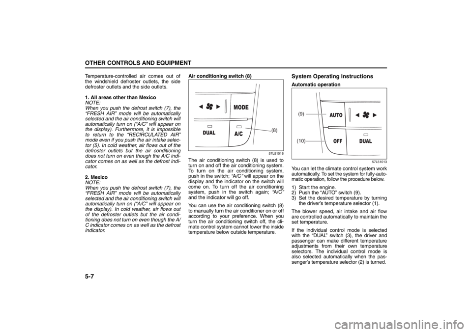
The air conditioning switch (8) is used to
turn on and off the air conditioning system.
To turn on the air conditioning system,
push in the switch; “A/C” will appear on the
display and the indicator on the switch will
come on. To turn off the air conditioning
system, push in the switch again; “A/C”
and the indicator will go off.
You can use the air conditioning switch (8)
to manually turn the air conditioner on or off
according to your preference. When you
turn the air conditioning switch off, the cli-
mate control system cannot lower the inside
temperature below outside temperature.
System Operating InstructionsAutomatic operation
57L51013
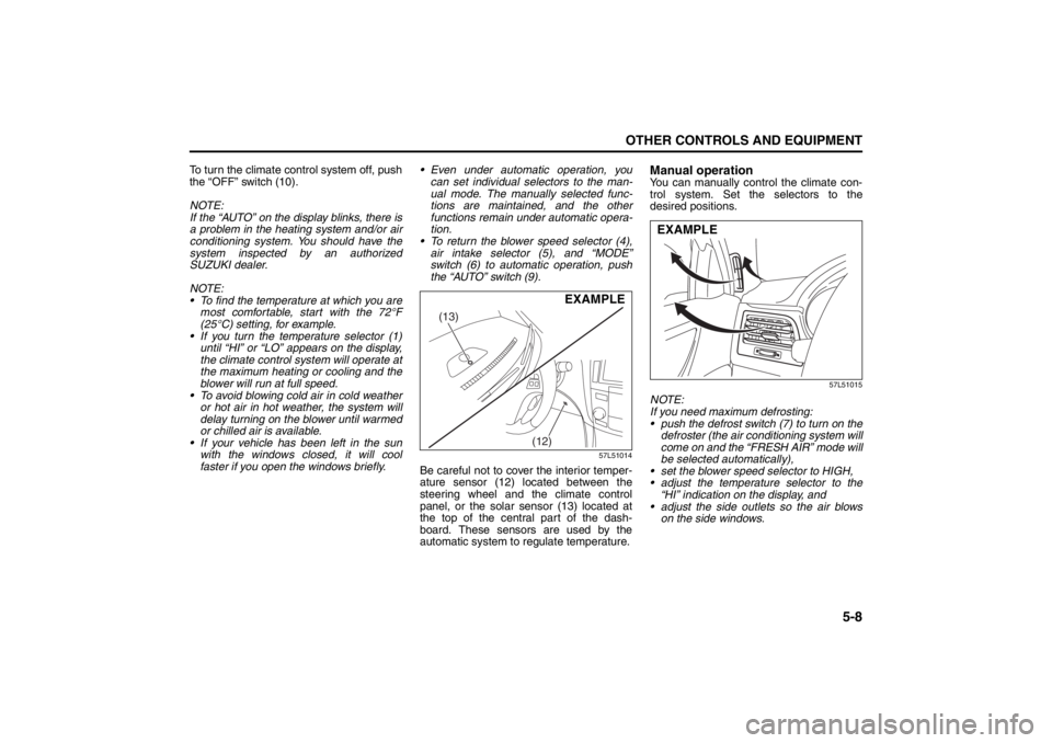
You can let the climate control system work
automatically. To set the system for fully-auto-
matic operation, follow the procedure below.
1) Start the engine.
2) Push the “AUTO” switch (9).
3) Set the desired temperature by turning
the driver’s temperature selector (1).
The blower speed, air intake and air flow
are controlled automatically to maintain the
set temperature.
If the individual control mode is selected
with the “DUAL” switch (3), the driver and
passenger can make different temperature
adjustments from their own temperature
selectors. The individual control mode is
also selected automatically when the pas-
senger’s temperature selector (2) is turned.
(8)
(9)
(10)
Folding Rear Seats: 3
Page 187 of 388
5-8
OTHER CONTROLS AND EQUIPMENT
57L20-03E
To turn the climate control system off, push
the “OFF” switch (10).
NOTE:
If the “AUTO” on the display blinks, there is
a problem in the heating system and/or air
conditioning system. You should have the
system inspected by an authorized
SUZUKI dealer.
NOTE:
To find the temperature at which you are
most comfortable, start with the 72°F
(25°C) setting, for example.
If you turn the temperature selector (1)
until “HI” or “LO” appears on the display,
the climate control system will operate at
the maximum heating or cooling and the
blower will run at full speed.
To avoid blowing cold air in cold weather
or hot air in hot weather, the system will
delay turning on the blower until warmed
or chilled air is available.
If your vehicle has been left in the sun
with the windows closed, it will cool
faster if you open the windows briefly. Even under automatic operation, you
can set individual selectors to the man-
ual mode. The manually selected func-
tions are maintained, and the other
functions remain under automatic opera-
tion.
To return the blower speed selector (4),
air intake selector (5), and “MODE”
switch (6) to automatic operation, push
the “AUTO” switch (9).
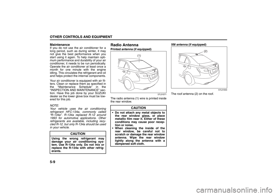
57L51014
Be careful not to cover the interior temper-
ature sensor (12) located between the
steering wheel and the climate control
panel, or the solar sensor (13) located at
the top of the central part of the dash-
board. These sensors are used by the
automatic system to regulate temperature.
Manual operationYou can manually control the climate con-
trol system. Set the selectors to the
desired positions.
57L51015
NOTE:
If you need maximum defrosting:
push the defrost switch (7) to turn on the
defroster (the air conditioning system will
come on and the “FRESH AIR” mode will
be selected automatically),
set the blower speed selector to HIGH,
adjust the temperature selector to the
“HI” indication on the display, and
adjust the side outlets so the air blows
on the side windows.
(13)
(12)
EXAMPLE
EXAMPLE
Folding Rear Seats: 3
Page 188 of 388
5-9OTHER CONTROLS AND EQUIPMENT
57L20-03E
MaintenanceIf you do not use the air conditioner for a
long period, such as during winter, it may
not give the best performance when you
start using it again. To help maintain opti-
mum performance and durability of your air
conditioner, it needs to be run periodically.
Operate the air conditioner at least once a
month for one minute with the engine
idling. This circulates the refrigerant and oil
and helps protect the internal components.
Your air conditioner is equipped with air fil-
ters. Clean or replace them as specified in
the “Maintenance Schedule” in the
“INSPECTION AND MAINTENANCE” sec-
tion. Have this job done by your SUZUKI
dealer as the lower glove box must be low-
ered for this job.
NOTE:
Your vehicle uses the air conditioning
refrigerant HFC-134a, commonly called
“R-134a”. R-134a replaced R-12 around
1993 for automotive applications. Other
refrigerants are available, including recy-
cled R-12, but only R-134a should be used
in your vehicle.
Radio AntennaPrinted antenna (if equipped)
57L51071
The radio antenna (1) wire is printed inside
the rear window.XM antenna (if equipped)
57L51053
The roof antenna (2) on the roof.
CAUTION
Using the wrong refrigerant may
damage your air conditioning sys-
tem. Use R-134a only. Do not mix or
replace the R-134a with other refrig-
erants.
CAUTION
Do not attach any metal objects to
the rear window glass, or place
metallic film near it. Either of these
conditions may cause poor recep-
tion or noise.
When cleaning the inside of the
rear window, be careful not to
scratch or damage the rear window
antenna. Wipe the rear window
lightly along the antenna with a
dampened soft cloth.
(1)
(2)
Folding Rear Seats: 3
Armrest: 3