clock SUZUKI KIZASHI 2010 1.G Owners Manual
[x] Cancel search | Manufacturer: SUZUKI, Model Year: 2010, Model line: KIZASHI, Model: SUZUKI KIZASHI 2010 1.GPages: 388, PDF Size: 4.94 MB
Page 53 of 388
2-34
BEFORE DRIVING
57L20-03E
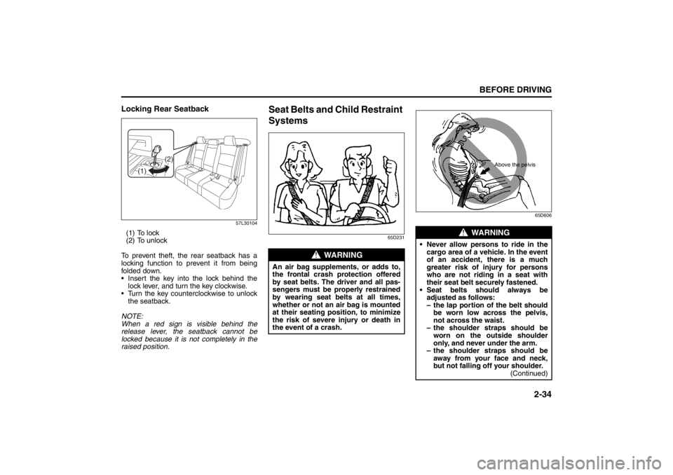
Locking Rear Seatback
57L30104
(1) To lock
(2) To unlock
To prevent theft, the rear seatback has a
locking function to prevent it from being
folded down.
Insert the key into the lock behind the
lock lever, and turn the key clockwise.
Turn the key counterclockwise to unlock
the seatback.
NOTE:
When a red sign is visible behind the
release lever, the seatback cannot be
locked because it is not completely in the
raised position.
Seat Belts and Child Restraint
Systems
65D23165D606
(1)(2)
WARNING
An air bag supplements, or adds to,
the frontal crash protection offered
by seat belts. The driver and all pas-
sengers must be properly restrained
by wearing seat belts at all times,
whether or not an air bag is mounted
at their seating position, to minimize
the risk of severe injury or death in
the event of a crash.
WARNING
Never allow persons to ride in the
cargo area of a vehicle. In the event
of an accident, there is a much
greater risk of injury for persons
who are not riding in a seat with
their seat belt securely fastened.
Seat belts should always be
adjusted as follows:
– the lap portion of the belt should
be worn low across the pelvis,
not across the waist.
– the shoulder straps should be
worn on the outside shoulder
only, and never under the arm.
– the shoulder straps should be
away from your face and neck,
but not falling off your shoulder.
(Continued)
Above the pelvis
Seat Belts and Child Restraint Systems: 3
Supplemental Restraint System (advanced air bags):
3, 9, 12
Page 98 of 388
2-79BEFORE DRIVING
57L20-03E
If the low fuel warning light (1) comes on,
fill the fuel tank immediately.
When the low fuel warning light (1) comes
on, a ding sounds once to remind you to fill
the fuel.
If you do not fill the fuel, a ding sounds
every time you press the engine switch to
change the ignition mode to “ON”.
NOTE:
The activation point of the low fuel warning
light (1) varies depending on road condi-
tions (for example, slope or curve) and
driving conditions because of fuel moving
in the tank.
The mark (2) indicates that the fuel filler
door is located on the left side of the vehi-
cle.
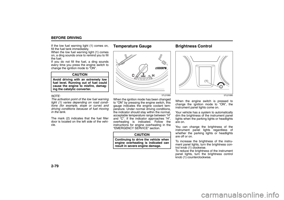
Temperature Gauge
57L21060
When the ignition mode has been changed
to “ON” by pressing the engine switch, this
gauge indicates the engine coolant tem-
perature. Under normal driving conditions,
the indicator should stay within the normal,
acceptable temperature range between “H”
and “C”. If the indicator approaches “H”,
overheating is indicated. Follow the
instructions for engine overheating in the
“EMERGENCY SERVICE” section.
Brightness Control
57L21080
When the engine switch is pressed to
change the ignition mode to “ON”, the
instrument panel lights come on.
Your vehicle has a system to automatically
dim the brightness of the instrument panel
lights when the parking lights or headlights
are on.
You can change the brightness of the
instrument panel lights regardless of
whether the parking lights or headlights
are off or on.
To increase the brightness of the instru-
ment panel lights, turn the brightness con-
trol knob (1) clockwise.
To reduce the brightness of the instrument
panel lights, turn the brightness control
knob (1) counterclockwise.
CAUTION
Avoid driving with an extremely low
fuel level. Running out of fuel could
cause the engine to misfire, damag-
ing the catalytic converter.
CAUTION
Continuing to drive the vehicle when
engine overheating is indicated can
result in severe engine damage.
(1)
Page 196 of 388

5-17OTHER CONTROLS AND EQUIPMENT
57L20-03E
Turning power on/off
Press the VOL PUSH POWER knob (1).
The unit starts in the function mode it was
in when the power was turned off last.
Adjusting the clock
1) Press and hold the H button (4) for 1
second or longer.
2) Press the H button (4) to adjust the
hours. Press and hold H button (4) to
successive change.
3) Press the M button (5).
4) Press the M button (5) to adjust the
minutes. Press and hold M button (5)
to successive change.
NOTE:
If no operation takes place for more than
3 seconds, the displayed time is fixed.
Pressing the H button (4) and M button
(5) simultaneously allows users to set
the clock on the hour. If “the minute” of
the clock is between 31 and 59, “the
hour” of the clock advances 1 hour.Adjusting the volume
Turn the VOL PUSH POWER knob (1).
Turning it clockwise increases the volume;
turning it counterclockwise decreases the
volume.
NOTE:
While driving, adjust the volume to an
extent that sound and/or noise coming
from outside the car can be heard.
Mute
Press the MUTE button (3).
Press the MUTE button (3) again, it
returns to the original volume.Adjusting bass/middle/treble/balance/
fader
1) Press the TUNE FOLDER PUSH
SOUND knob (2).
Each time it is pressed, sound adjust-
ment is changed as follows:
For standard specifications
Bass adjustment (BASS 0)
Treble adjustment (TRE 0)
Balance adjustment (BAL 0)
Fader adjustment (FADE 0)
AVC adjustment (LEVEL 2)
Page 219 of 388

5-40
OTHER CONTROLS AND EQUIPMENT
57L20-03E
Receiving a call
Press the Off Hook button (7) to receive a
call.
Ending a call
Press the On Hook button (8) to end a call.
Rejecting a call (only for supported-
models)
Press the On Hook button (8) to reject a
incoming call.Adjusting the listening volume
Turn the VOL PUSH POWER knob (2)
during a call.
Turning it clockwise increases the vol-
ume; turning it counterclockwise
decreases the volume.
Lean the VOL switch (9) during a call.
Leaning to the upper side increases the
volume; leaning the lower side
decreases the volume.
Adjusting the ring volume
Turn the VOL PUSH POWER knob (2)
while a call coming in.
Turning it clockwise increases the vol-
ume; turning it counterclockwise
decreases the volume.
Lean the VOL switch (9) while a call
coming in.
Leaning to the upper side increases the
volume; leaning the lower side
decreases the volume.Dialing by using Redial/Callback
The last dialed number is dialed.
NOTE:
Up to latest 5 calls can be stored for each.
1) Press the Off Hook button (7).
The Bluetooth
® main menu appears.
2) Turn the TUNE FOLDER PUSH
SOUND knob (1) to select “Redial” or
“Callback”, and press the TUNE
FOLDER PUSH SOUND knob (1) to
determine the selection.
For calling from the outgoing call
record or incoming call record, “Redial”
or “Callback” shall be selected, respec-
tively.
3) Turn the TUNE FOLDER PUSH
SOUND knob (1) to select a number,
and press the TUNE FOLDER PUSH
SOUND knob (1) to determine the
selection.
4) Turn the TUNE FOLDER PUSH
SOUND knob (1) to select “Dial”, and
press the TUNE FOLDER PUSH
SOUND knob (1) to determine the
selection.
The selected number is dialed.
NOTE:
Selection of “Go Back” displays the pre-
vious menu.
Pressing the Off Hook button (7) in the
2nd step allows users to forward to the
3rd step with a single motion.
Page 253 of 388
5-74
OTHER CONTROLS AND EQUIPMENT
57L20-03E
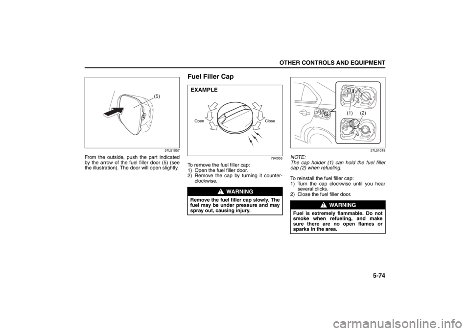
57L51057
From the outside, push the part indicated
by the arrow of the fuel filler door (5) (see
the illustration). The door will open slightly.
Fuel Filler Cap
79K053
To remove the fuel filler cap:
1) Open the fuel filler door.
2) Remove the cap by turning it counter-
clockwise.
57L51019
NOTE:
The cap holder (1) can hold the fuel filler
cap (2) when refueling.
To reinstall the fuel filler cap:
1) Turn the cap clockwise until you hear
several clicks.
2) Close the fuel filler door.
(5)
WARNING
Remove the fuel filler cap slowly. The
fuel may be under pressure and may
spray out, causing injury.Open CloseEXAMPLE
WARNING
Fuel is extremely flammable. Do not
smoke when refueling, and make
sure there are no open flames or
sparks in the area.
(1) (2)
Page 264 of 388
5-85OTHER CONTROLS AND EQUIPMENT
57L20-03E
65D612
Be sure to close the sunroof when you
leave the vehicle unattended.
Periodically inspect the guide rail for dirt
and clean it if any dirt has accumulated.
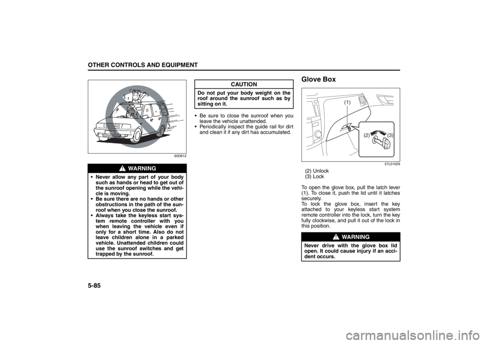
Glove Box
57L51029
(2) Unlock
(3) Lock
To open the glove box, pull the latch lever
(1). To close it, push the lid until it latches
securely.
To lock the glove box, insert the key
attached to your keyless start system
remote controller into the lock, turn the key
fully clockwise, and pull it out of the lock in
this position.
WARNING
Never allow any part of your body
such as hands or head to get out of
the sunroof opening while the vehi-
cle is moving.
Be sure there are no hands or other
obstructions in the path of the sun-
roof when you close the sunroof.
Always take the keyless start sys-
tem remote controller with you
when leaving the vehicle even if
only for a short time. Also do not
leave children alone in a parked
vehicle. Unattended children could
use the sunroof switches and get
trapped by the sunroof.
CAUTION
Do not put your body weight on the
roof around the sunroof such as by
sitting on it.
WARNING
Never drive with the glove box lid
open. It could cause injury if an acci-
dent occurs.
(1)
(3) (2)
Page 302 of 388
7-17INSPECTION AND MAINTENANCE
57L20-03E
5) Reinstall the drain plug and gasket.
Tighten the plug with a wrench to the
specified torque.
6) Reinstall the engine under cover.
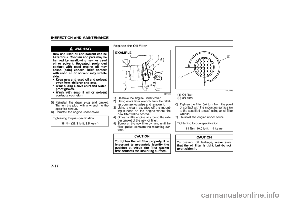
Replace the Oil Filter
60A198
1) Remove the engine under cover.
2) Using an oil filter wrench, turn the oil fil-
ter counterclockwise and remove it.
3) Using a clean rag, wipe off the mount-
ing surface on the engine where the
new filter will be seated.
4) Smear a little engine oil around the rub-
ber gasket of the new oil filter.
5) Screw on the new filter by hand until the
filter gasket contacts the mounting sur-
face.
54G093
(1) Oil filter
(2) 3/4 turn
6) Tighten the filter 3/4 turn from the point
of contact with the mounting surface (or
to the specified torque) using an oil filter
wrench.
7) Reinstall the engine under cover.
WARNING
New and used oil and solvent can be
hazardous. Children and pets may be
harmed by swallowing new or used
oil or solvent. Repeated, prolonged
contact with used engine oil may
cause [skin] cancer. Brief contact
with used oil or solvent may irritate
skin.
Keep new and used oil and solvent
away from children and pets.
Wear a long-sleeve shirt and water-
proof gloves.
Wash with soap if oil or solvent
contacts your skin.
Tightening torque specification
35 Nm (25.3 lb-ft, 3.5 kg-m)
CAUTION
To tighten the oil filter properly, it is
important to accurately identify the
position at which the filter gasket
first contacts the mounting surface.EXAMPLE
Tightening torque specification
14 Nm (10.0 lb-ft, 1.4 kg-m)
CAUTION
To prevent oil leakage, make sure
that the oil filter is tight, but do not
overtighten it.
Page 332 of 388
7-47INSPECTION AND MAINTENANCE
57L20-03E
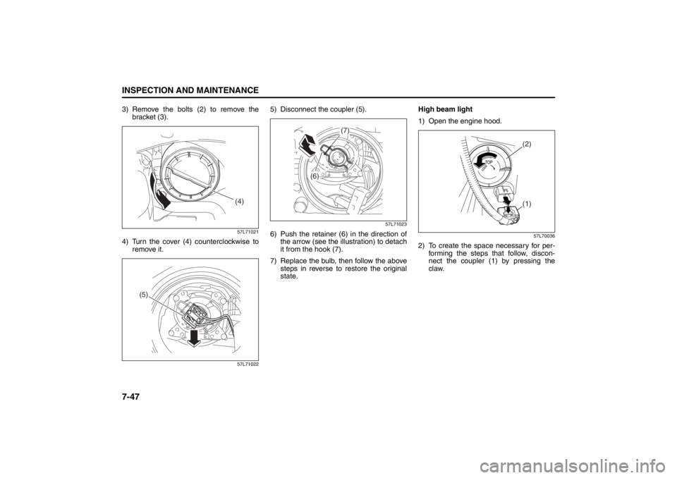
3) Remove the bolts (2) to remove the
bracket (3).
57L71021
4) Turn the cover (4) counterclockwise to
remove it.
57L71022
5) Disconnect the coupler (5).
57L71023
6) Push the retainer (6) in the direction of
the arrow (see the illustration) to detach
it from the hook (7).
7) Replace the bulb, then follow the above
steps in reverse to restore the original
state.High beam light
1) Open the engine hood.
57L70036
2) To create the space necessary for per-
forming the steps that follow, discon-
nect the coupler (1) by pressing the
claw.
(4)
(5)
(7)
(6)
(2)(1)
Page 333 of 388
7-48
INSPECTION AND MAINTENANCE
57L20-03E
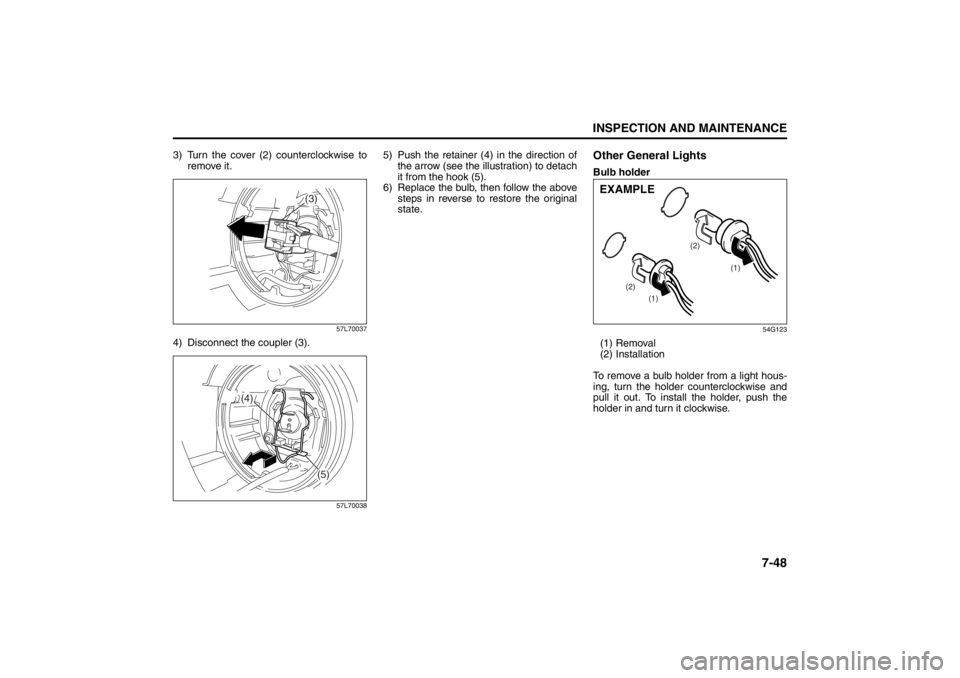
3) Turn the cover (2) counterclockwise to
remove it.
57L70037
4) Disconnect the coupler (3).
57L70038
5) Push the retainer (4) in the direction of
the arrow (see the illustration) to detach
it from the hook (5).
6) Replace the bulb, then follow the above
steps in reverse to restore the original
state.
Other General LightsBulb holder
54G123
(1) Removal
(2) Installation
To remove a bulb holder from a light hous-
ing, turn the holder counterclockwise and
pull it out. To install the holder, push the
holder in and turn it clockwise.
(3)
(4)
(5)
(1)
(1) (2)(2)
EXAMPLE
Page 334 of 388
7-49INSPECTION AND MAINTENANCE
57L20-03E
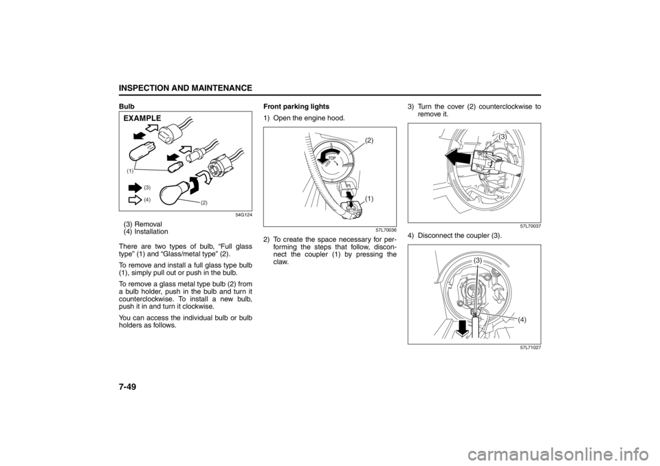
Bulb
54G124
(3) Removal
(4) Installation
There are two types of bulb, “Full glass
type” (1) and “Glass/metal type” (2).
To remove and install a full glass type bulb
(1), simply pull out or push in the bulb.
To remove a glass metal type bulb (2) from
a bulb holder, push in the bulb and turn it
counterclockwise. To install a new bulb,
push it in and turn it clockwise.
You can access the individual bulb or bulb
holders as follows.Front parking lights
1) Open the engine hood.
57L70036
2) To create the space necessary for per-
forming the steps that follow, discon-
nect the coupler (1) by pressing the
claw.3) Turn the cover (2) counterclockwise to
remove it.
57L70037
4) Disconnect the coupler (3).
57L71027
(1)
(2) (3)
(4)EXAMPLE
(2)(1)
(3)
(4)
(3)