tow SUZUKI MARUTI 2005 1.G Owners Manual
[x] Cancel search | Manufacturer: SUZUKI, Model Year: 2005, Model line: MARUTI, Model: SUZUKI MARUTI 2005 1.GPages: 136, PDF Size: 2.93 MB
Page 1 of 136
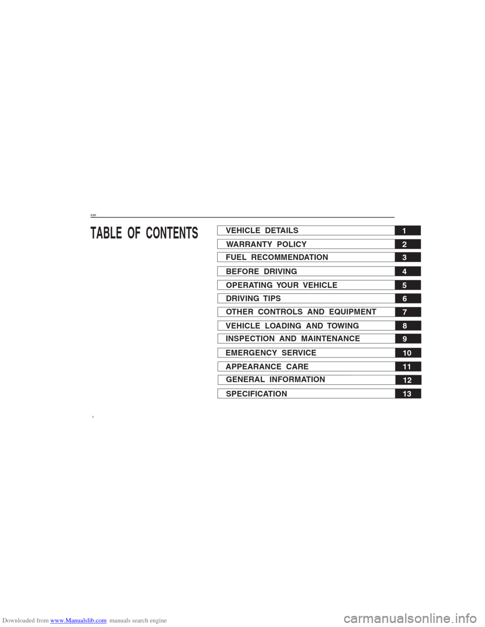
Downloaded from www.Manualslib.com manuals search engine 183KTABLE OF CONTENTS
1
VEHICLE DETAILS
2
WARRANTY POLICY
3
FUEL RECOMMENDATION
4
BEFORE DRIVING
5
OPERATING YOUR VEHICLE
6
DRIVING TIPS
7
OTHER CONTROLS AND EQUIPMENT
8
VEHICLE LOADING AND TOWING
9
INSPECTION AND MAINTENANCE
10
EMERGENCY SERVICE
11
APPEARANCE CARE
12
GENERAL INFORMATION
13
SPECIFICATION
Page 14 of 136
Downloaded from www.Manualslib.com manuals search engine 1483K
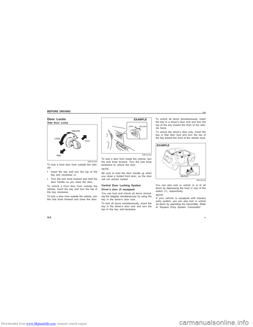
Door LocksSide Door Locks
To lock a door from inside the vehicle, turn
the lock knob forward. Turn the lock knob
backward to unlock the door.
NOTE:
Be sure to hold the door handle up when
you close a locked front door, as the door
will not remain locked.
EXAMPLE BEFORE DRIVING
4-2
83K-02-003
To lock a front door from outside the vehi-
cle:
Insert the key and turn the top of the
key anti clockwise or
Turn the lock knob forward and hold the
door handle as you close the door.
To unlock a front door from outside the
vehicle, insert the key and turn the top of
the key clockwise.
To lock a door from outside the vehicle, turn
the lock knob forward and close the door.
83K-02-004
Central Door Locking SystemDriver’s door (if equipped)
You can lock and unlock all doors (includ-
ing the tailgate) simultaneously by using the
key in the driver’s door lock.
To lock all doors simultaneously, insert the
key in the driver’s door lock and turn the
top of the key anti-clockwiseTo unlock all doors simultaneously, insert
the key in a driver’s door lock and turn the
top of the key toward the front of the vehi-
cle twice.
To unlock the driver’s door only, insert the
key in that door lock and turn the top of
the key toward the front of the vehicle once.
You can also lock or unlock (4 or 5) all
doors by depressing the front or rear of the
switch (1), respectively.
NOTE:
If your vehicle is equipped with keyless
entry system, you can also lock or unlock
all doors by operating the transmitter. Refer
to “Keyless Entry System Transmitter”.
83K-02-006
EXAMPLE
Page 17 of 136
Downloaded from www.Manualslib.com manuals search engine 1783K
BEFORE DRIVING
4-5
Be sure the doors are locked after you
operate the “LOCK” button. If no door is
opened within about 30 seconds after the
“UNLOCK” button is operated, the doors will
automatically lock again.NOTE:
The maximum operating distance of the
keyless entry system transmitter is about
5 m (16 ft.), but this can vary depending
on the surroundings, especially near
other transmitting devices such as radio
towers or CB (citizen’s band).
The door locks can not be operated with
the transmitter if the ignition switch is in
a position other than “LOCK”, or the igni-
tion key is inserted in the ignition switch.
When any door is open, the door locks
can be operated only unlock with the
transmitter, and the turn signal light will
not flash.
If you lose one of the transmitters, con-
tact your MARUTI SUZUKI authorized
dealer as soon as possible for a replace-
ment. Be sure to have your dealer pro-
gram the new transmitter code in your
vehicle’s memory so that the old code
is erased.
CAUTION
The transmitter is a sensitive elec-
tronic instrument. To avoid damaging
the transmitter:
Do not expose it to impacts, mois-
ture or high temperature such as by
leaving it on the dashboard under
direct sunlight.
Keep the transmitter away from
magnetic objects such as a televi-
sion.
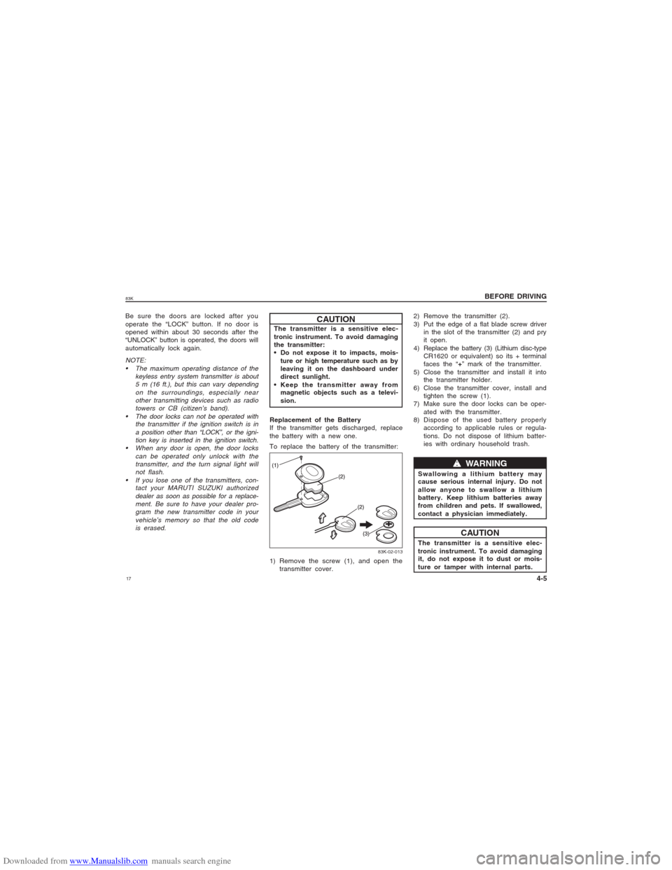
Replacement of the Battery
If the transmitter gets discharged, replace
the battery with a new one.
To replace the battery of the transmitter:
83K-02-013
1) Remove the screw (1), and open the
transmitter cover.2) Remove the transmitter (2).
3) Put the edge of a flat blade screw driver
in the slot of the transmitter (2) and pry
it open.
4) Replace the battery (3) (Lithium disc-type
CR1620 or equivalent) so its + terminal
faces the “+” mark of the transmitter.
5) Close the transmitter and install it into
the transmitter holder.
6) Close the transmitter cover, install and
tighten the screw (1).
7) Make sure the door locks can be oper-
ated with the transmitter.
8) Dispose of the used battery properly
according to applicable rules or regula-
tions. Do not dispose of lithium batter-
ies with ordinary household trash.
CAUTIONw ww w
w WARNING
Swallowing a lithium battery may
cause serious internal injury. Do not
allow anyone to swallow a lithium
battery. Keep lithium batteries away
from children and pets. If swallowed,
contact a physician immediately.
The transmitter is a sensitive elec-
tronic instrument. To avoid damaging
it, do not expose it to dust or mois-
ture or tamper with internal parts.
Page 23 of 136
Downloaded from www.Manualslib.com manuals search engine 2383K
BEFORE DRIVING
4-11
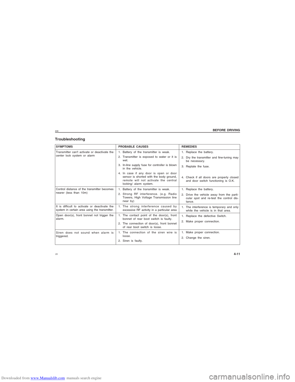
SYMPTOMS
Transmitter can't activate or deactivate the
center lock system or alarm
Control distance of the transmitter becomes
nearer (less than 10m)
It is difficult to activate or deactivate the
system in certain area using the transmitter.
Open door(s), front bonnet not trigger the
alarm.
Siren does not sound when alarm is
triggered.Troubleshooting
PROBABLE CAUSES
1. Battery of the transmitter is weak.
2. Transmitter is exposed to water or it is
wet.
3. In-line supply fuse for controller is blown
in the vehicle.
4. In case if any door is open or door
sensor is shorted with the body ground,
remote will not activate the central
locking/ alarm system.
1. Battery of the transmitter is weak.
2. Strong RF interference. (e.g. Radio
Towers, High Voltage Transmission line
near by)
1. The strong interference caused by
excessive RF activity in a particular area
1. The contact point of the door(s), front
bonnet of rear boot switch is faulty.
2. The connection of door(s), front bonnet
of rear boot switch is loose.
1. The connection of the siren wire is
loose.
2. Siren is faulty.REMEDIES
1. Replace the battery.
2. Dry the transmitter and fine-tuning may
be necessary.
3. Replate the fuse.
4. Check if all doors are properly closed
and door switch functioning is O.K.
1. Replace the battery.
2. Drive the vehicle away from the parti-
cular spot and re-test the control dis-
tance.
1. The interference is temporary and only
while the vehicle is in that area.
1. Replace the defective Switch.
2. Make proper connection.
1. Make proper connection.
2. Change the siren.
Page 41 of 136
Downloaded from www.Manualslib.com manuals search engine 4183K
BEFORE DRIVING
4-29
The light also comes on together with the
ABS warning light when the rear brake force
control function (Proportioning valve
function) of the ABS system fails.
If the brake system warning light comes on
while you are driving the vehicle, it may
mean that there is something wrong with
the vehicle’s brake system. If this happens,
you should:
1) Pull off the road and stop carefully.
w ww w
w WARNING
Remember that stopping distance may
be longer, you may have to push
harder on the pedal, and the pedal
may go down farther than normal.
w ww w
w WARNING
If the brake system warning light
does not go out after the engine
has been started and the parking
brake has been fully released.
If the brake system warning light
does not come on when the ignition
switch is turned to the “ON” or
“START” position.
If the brake system warning light
comes on at any time during vehi-
cle operation.
2) Test the brakes by carefully starting and
stopping at the side of the road.
– If you determine that it is safe, drive
carefully at low speed to the nearest
MARUTI SUZUKI dealer for repairs, or
– Have the vehicle towed to the nearest
MARUTI SUZUKI dealer for repairs.
V VV V
V
w ww w
w WARNING
If any of the following conditions
occur, you should immediately ask
your MARUTI SUZUKI dealer to
inspect the brake system.
V VV V
V
NOTE:
Because the disc brake system is self-
adjusting, the fluid level will drop as the
brake pads become worn. Replenishing the
brake fluid reservoir is considered normal
periodic maintenance.Seat Belt Warning Light (if
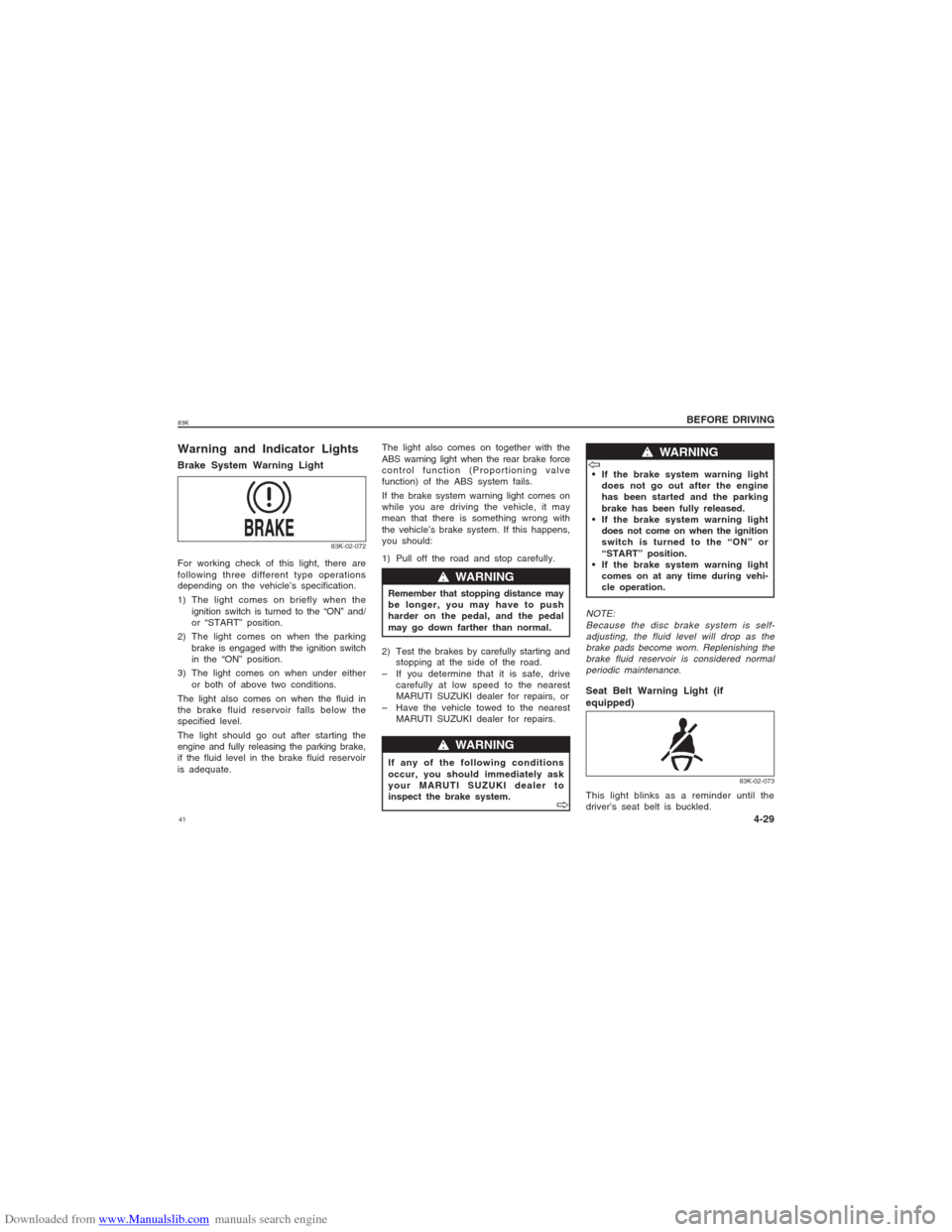
equipped)This light blinks as a reminder until the
driver’s seat belt is buckled.
83K-02-073
Warning and Indicator LightsBrake System Warning LightFor working check of this light, there are
following three different type operations
depending on the vehicle’s specification.
1) The light comes on briefly when the
ignition switch is turned to the “ON” and/
or “START” position.
2) The light comes on when the parking
brake is engaged with the ignition switch
in the “ON” position.
3) The light comes on when under either
or both of above two conditions.
The light also comes on when the fluid in
the brake fluid reservoir falls below the
specified level.
The light should go out after starting the
engine and fully releasing the parking brake,
if the fluid level in the brake fluid reservoir
is adequate.
83K-02-072
Page 51 of 136
Downloaded from www.Manualslib.com manuals search engine 5183KEXAMPLE
83K-02-098
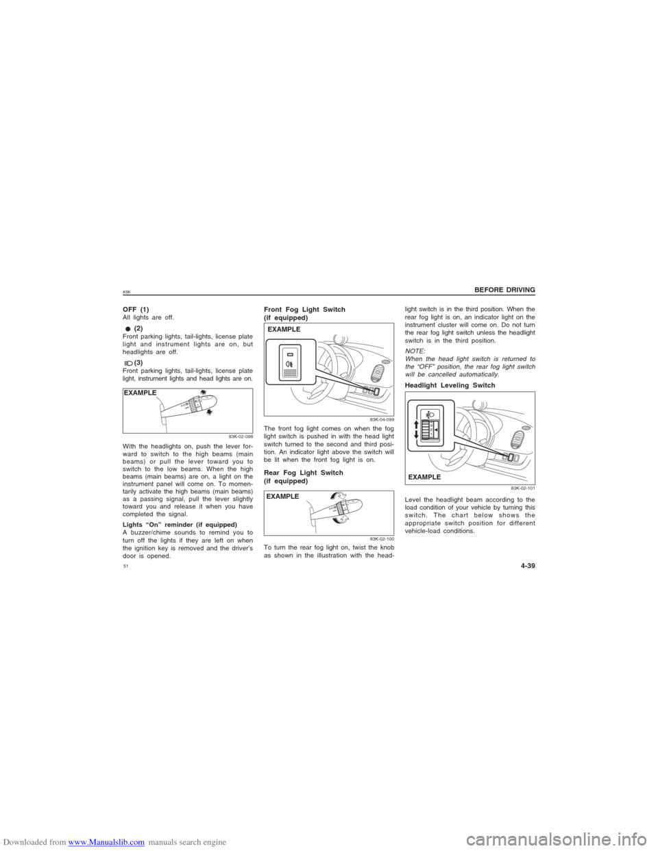
With the headlights on, push the lever for-
ward to switch to the high beams (main
beams) or pull the lever toward you to
switch to the low beams. When the high
beams (main beams) are on, a light on the
instrument panel will come on. To momen-
tarily activate the high beams (main beams)
as a passing signal, pull the lever slightly
toward you and release it when you have
completed the signal.
Lights “On” reminder (if equipped)
A buzzer/chime sounds to remind you to
turn off the lights if they are left on when
the ignition key is removed and the driver’s
door is opened.OFF (1)All lights are off. (2)Front parking lights, tail-lights, license plate
light and instrument lights are on, but
headlights are off. (3)Front parking lights, tail-lights, license plate
light, instrument lights and head lights are on.
Front Fog Light Switch
(if equipped)
83K-04-099
EXAMPLEThe front fog light comes on when the fog
light switch is pushed in with the head light
switch turned to the second and third posi-
tion. An indicator light above the switch will
be lit when the front fog light is on.Rear Fog Light Switch
(if equipped)
83K-02-100
To turn the rear fog light on, twist the knob
as shown in the illustration with the head-
light switch is in the third position. When the
rear fog light is on, an indicator light on the
instrument cluster will come on. Do not turn
the rear fog light switch unless the headlight
switch is in the third position.NOTE:
When the head light switch is returned to
the “OFF” position, the rear fog light switch
will be cancelled automatically.Headlight Leveling Switch
83K-02-101
EXAMPLELevel the headlight beam according to the
load condition of your vehicle by turning this
switch. The chart below shows the
appropriate switch position for different
vehicle-load conditions.
BEFORE DRIVING
4-39 EXAMPLE
Page 53 of 136
Downloaded from www.Manualslib.com manuals search engine 5383K
BEFORE DRIVING
4-41
position, the wipers operate at a steady high
speed. To turn off the wipers, move the
lever back to the “OFF” position.
Move the lever up and hold it to the “MIST”
position, the windshield wipers will turn on
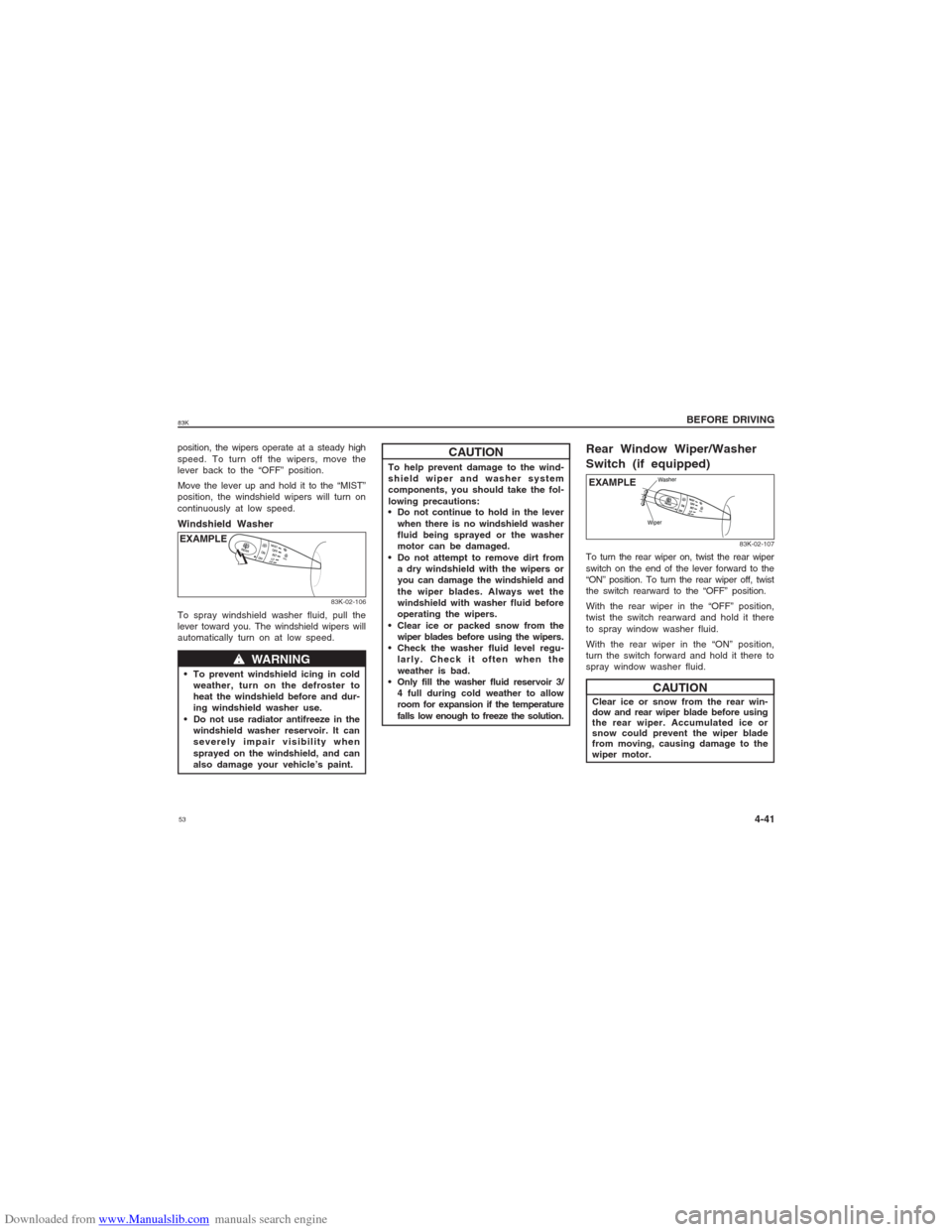
continuously at low speed.Windshield Washer
83K-02-106
w ww w
w WARNING
To prevent windshield icing in cold
weather, turn on the defroster to
heat the windshield before and dur-
ing windshield washer use.
Do not use radiator antifreeze in the
windshield washer reservoir. It can
severely impair visibility when
sprayed on the windshield, and can
also damage your vehicle’s paint.EXAMPLE
CAUTION
To help prevent damage to the wind-
shield wiper and washer system
components, you should take the fol-
lowing precautions:
Do not continue to hold in the lever
when there is no windshield washer
fluid being sprayed or the washer
motor can be damaged.
Do not attempt to remove dirt from
a dry windshield with the wipers or
you can damage the windshield and
the wiper blades. Always wet the
windshield with washer fluid before
operating the wipers.
Clear ice or packed snow from the
wiper blades before using the wipers.
Check the washer fluid level regu-
larly. Check it often when the
weather is bad.
Only fill the washer fluid reservoir 3/
4 full during cold weather to allow
room for expansion if the temperature
falls low enough to freeze the solution.
To spray windshield washer fluid, pull the
lever toward you. The windshield wipers will
automatically turn on at low speed.
EXAMPLE
83K-02-107
Rear Window Wiper/Washer
Switch (if equipped)To turn the rear wiper on, twist the rear wiper
switch on the end of the lever forward to the
“ON” position. To turn the rear wiper off, twist
the switch rearward to the “OFF” position.
With the rear wiper in the “OFF” position,
twist the switch rearward and hold it there
to spray window washer fluid.
With the rear wiper in the “ON” position,
turn the switch forward and hold it there to
spray window washer fluid.
Clear ice or snow from the rear win-
dow and rear wiper blade before using
the rear wiper. Accumulated ice or
snow could prevent the wiper blade
from moving, causing damage to the
wiper motor.
CAUTION
Page 68 of 136
Downloaded from www.Manualslib.com manuals search engine 6883K
To minimize the possibility of catalyst
or other vehicle damage:
Maintain the engine in the proper
operating condition.
In the event of an engine malfunc-
tion, particularly one involving
engine misfire or other apparent
loss of performance, have the vehi-
cle serviced promptly.
Do not turn off the engine or inter-
rupt the ignition when the transmis-
sion is in gear and the vehicle is in
motion.
Do not try to start the engine by
pushing or towing the vehicle, or
coasting down a hill.
Do not idle the engine with any
spark plug wires disconnected or
removed, such as during diagnostic
testing.
Do not idle the vehicle for pro-
longed periods if idling seems rough
or there are other malfunctions.
Do not allow the fuel tank to get
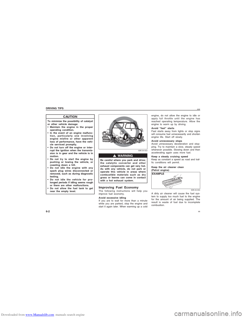
near the empty level.Be careful where you park and drive;
the catalytic converter and other
exhaust components can get very hot.
As with any vehicle, do not park or
operate this vehicle in areas where
combustible materials such as dry
grass or leaves can come in contact
with a hot exhaust system.
w ww w
w WARNING
83K-04-003
engine, do not allow the engine to idle or
apply full throttle until the engine has
reached operating temperature. Allow the
engine to warm up by driving.
Avoid “fast” starts
Fast starts away from lights or stop signs
will consume fuel unnecessarily and shorten
engine life. Start off slowly.
Avoid unnecessary stops
Avoid unnecessary deceleration and stop-
ping. Try to maintain a slow, steady speed
whenever possible. Slowing down and then
accelerating again uses more fuel.
Keep a steady cruising speed
Keep as constant a speed as road and traf-
fic conditions will permit.
DRIVING TIPS
6-2
CAUTION
Improving Fuel EconomyThe following instructions will help you
improve fuel economy.
Avoid excessive idling
If you are to wait for more than a minute
while you are parked, stop the engine and
start it again later. When warming up a coldKeep the air cleaner clean
(Petrol engine)
EXAMPLE
83K-04-004
A dirty air cleaner will cause the fuel sys-
tem to supply too much fuel to the engine
for the amount of air being supplied. The
result is waste of fuel due to incomplete
combustion.
Page 84 of 136
Downloaded from www.Manualslib.com manuals search engine 8483K
OTHER CONTROLS AND EQUIPMENT
7-10
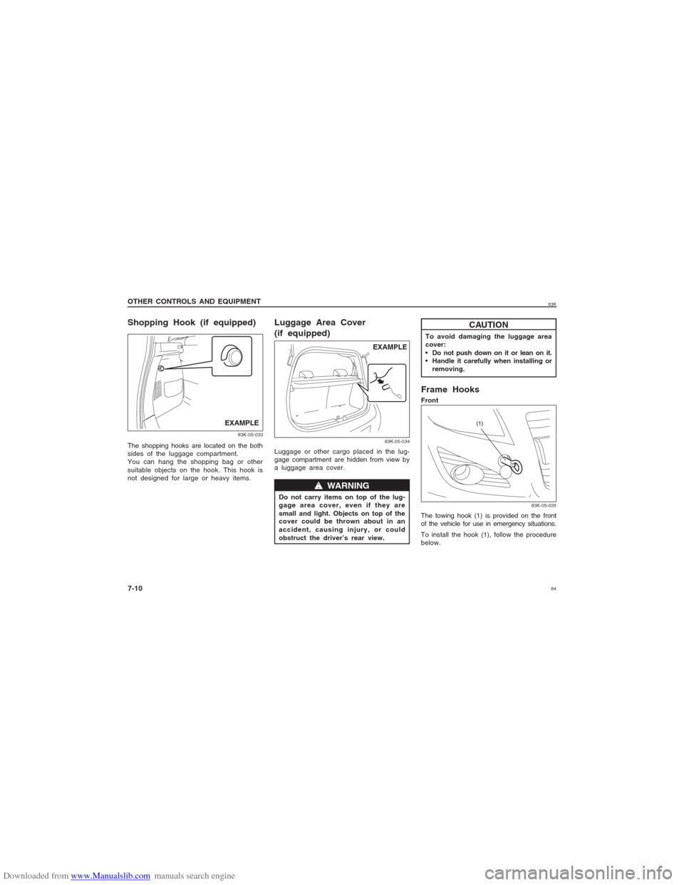
Luggage Area Cover
(if equipped)Luggage or other cargo placed in the lug-
gage compartment are hidden from view by
a luggage area cover.
83K-05-034
EXAMPLE
w ww w
w WARNING
Do not carry items on top of the lug-
gage area cover, even if they are
small and light. Objects on top of the
cover could be thrown about in an
accident, causing injury, or could
obstruct the driver’s rear view.
Shopping Hook (if equipped)
83K-05-033
EXAMPLE
The shopping hooks are located on the both
sides of the luggage compartment.
You can hang the shopping bag or other
suitable objects on the hook. This hook is
not designed for large or heavy items.
Frame HooksFront
The towing hook (1) is provided on the front
of the vehicle for use in emergency situations.
To install the hook (1), follow the procedure
below.
CAUTION
To avoid damaging the luggage area
cover:
Do not push down on it or lean on it.
Handle it carefully when installing or
removing.
83K-05-035
Page 85 of 136
Downloaded from www.Manualslib.com manuals search engine 8583K
OTHER CONTROLS AND EQUIPMENT
7-11
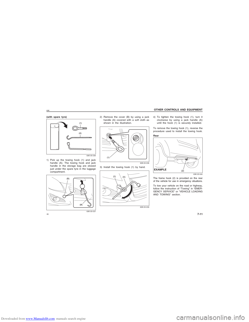
(with spare tyre)
83K-05-03683K-05-037
1) Pick up the towing hook (1) and jack
handle (A). The towing hook and jack
handle in the storage bag are stowed
just under the spare tyre in the luggage
compartment.2) Remove the cover (B) by using a jack
handle (A) covered with a soft cloth as
shown in the illustration.
83K-05-038
3) Install the towing hook (1) by hand.
83K-05-039
To remove the towing hook (1), reverse the
procedure used to install the towing hook.
Rear
83K-05-040
The frame hook (2) is provided on the rear
of the vehicle for use in emergency situations.
To tow your vehicle on the road or highway,
follow the instruction of “Towing” in “EMER-
GENCY SERVICE” or “VEHICLE LOADING
AND TOWING” section.EXAMPLE4) To tighten the towing hook (1), turn it
clockwise by using a jack handle (A)
until the hook (1) is securely installed.