Steering SUZUKI SWIFT 2000 1.G RG413 Service Owners Manual
[x] Cancel search | Manufacturer: SUZUKI, Model Year: 2000, Model line: SWIFT, Model: SUZUKI SWIFT 2000 1.GPages: 698, PDF Size: 16.01 MB
Page 192 of 698
STEERING WHEEL AND COLUMN 3C-19
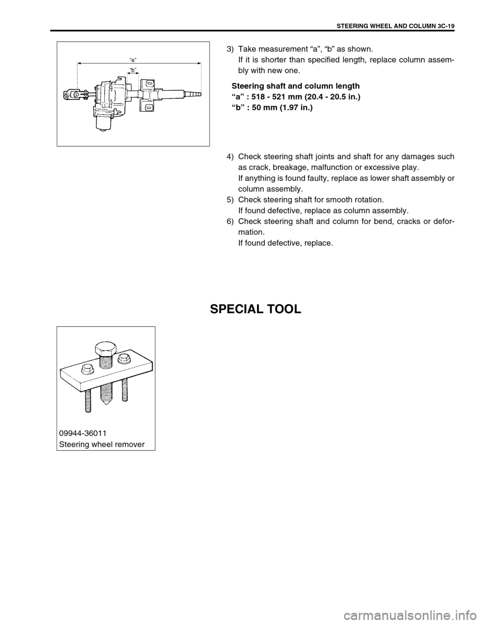
3) Take measurement “a”, “b” as shown.
If it is shorter than specified length, replace column assem-
bly with new one.
Steering shaft and column length
“a” : 518 - 521 mm (20.4 - 20.5 in.)
“b” : 50 mm (1.97 in.)
4) Check steering shaft joints and shaft for any damages such
as crack, breakage, malfunction or excessive play.
If anything is found faulty, replace as lower shaft assembly or
column assembly.
5) Check steering shaft for smooth rotation.
If found defective, replace as column assembly.
6) Check steering shaft and column for bend, cracks or defor-
mation.
If found defective, replace.
SPECIAL TOOL
09944-36011
Steering wheel remover
Page 193 of 698
3C-20 STEERING WHEEL AND COLUMN
Page 194 of 698
FRONT SUSPENSION 3D-1
6F1
6F2
6G
1A
6K
7A
7A1
7B1
7C1
3D
7F
8A
8B
8C
8D
8E
9
10
10A
10B
SECTION 3D
FRONT SUSPENSION
CONTENTS
GENERAL DESCRIPTION .............................. 3D-1
DIAGNOSIS ..................................................... 3D-3
STABILIZER BAR AND/OR BUSHING
CHECK ......................................................... 3D-3
STRUT ASSEMBLY CHECK ....................... 3D-3
SUSPENSION CONTROL ARM / STEERING
KNUCKLE CHECK ....................................... 3D-4
SUSPENSION CONTROL ARM BUSHING
CHECK ......................................................... 3D-4
SUSPENSION CONTROL ARM JOINT
CHECK ......................................................... 3D-4
FRONT SUSPENSION FASTENERS
CHECK ......................................................... 3D-5WHEEL DISC, NUT AND BEARING
CHECK ........................................................ 3D-5
ON-VEHICLE SERVICE .................................. 3D-6
STRUT ASSEMBLY..................................... 3D-6
STABILIZER BAR AND/OR BUSHINGS ..... 3D-9
WHEEL HUB AND STEERING
KNUCKLE .................................................. 3D-11
SUSPENSION CONTROL ARM /
BUSHING................................................... 3D-16
REQUIRED SERVICE MATERIAL................ 3D-19
SPECIAL TOOL ............................................ 3D-19
GENERAL DESCRIPTION
The front suspension is the strut type independent suspension. The upper end of a strut is anchored to the vehi-
cle body by a strut support. The strut and strut support are isolated by a rubber mount. A strut bearing is also
installed a little lower to the rubber mount.
The lower end of the strut is connected to the upper end of a steering knuckle and lower end of knuckle is
attached to the stud of a ball joint which is incorporated in a unit with a suspension control arm. And connected
to this steering knuckle is the tie rod end.
Thus, movement of the steering wheel is transmitted to the tie rod end and then to the knuckle, eventually caus-
ing the wheel-and-tire to move. In this operation, with the movement of the knuckle, the strut also rotates by
means of the strut bearing and lower ball joint.NOTE:
All front suspension fasteners are an important attaching part in that it could affect the perfor-
mance of vital parts and systems, and/or could result in major repair expense. They must be
replaced with one of the same part number or with an equivalent part if replacement becomes nec-
essary. Do not use a replacement part of lesser quality or substitute design. Torque values must be
used as specified during reassembly to assure proper retention of this part.
Never attempt to heat, quench or straighten any front suspension part. Replace it with a new part or
damage to the part may result.
Page 195 of 698
![SUZUKI SWIFT 2000 1.G RG413 Service Owners Manual 3D-2 FRONT SUSPENSION
1. Strut assembly 4. Wheel 7. Drive shaft [A] : FORWARD
2. Stabilizer bar 5. Suspension control arm 8. Tie rod Tightening torque
3. Steering knuckle 6. Vehicle body 9. Brake disc SUZUKI SWIFT 2000 1.G RG413 Service Owners Manual 3D-2 FRONT SUSPENSION
1. Strut assembly 4. Wheel 7. Drive shaft [A] : FORWARD
2. Stabilizer bar 5. Suspension control arm 8. Tie rod Tightening torque
3. Steering knuckle 6. Vehicle body 9. Brake disc](/img/20/7606/w960_7606-194.png)
3D-2 FRONT SUSPENSION
1. Strut assembly 4. Wheel 7. Drive shaft [A] : FORWARD
2. Stabilizer bar 5. Suspension control arm 8. Tie rod Tightening torque
3. Steering knuckle 6. Vehicle body 9. Brake disc Do not reuse.
[A]
4
92
35
8
660 N·m(6.0 kg-m) 175 N·m(17.5 kg-m)
60 N·m(6.0 kg-m)
85 N·m(8.5 kg-m)
85 N·m(8.5 kg-m)
43 N·m(4.3 kg-m)
65 N·m(6.5 kg-m)
65 N·m(6.5 kg-m)
23 N·m(2.3 kg-m)
50 N·m(5.0 kg-m)
175 N·m(17.5 kg-m)
105 N·m(10.5 kg-m)
1
8
45 N·m (4.5kg-m) 7
5
4
9
Page 197 of 698

3D-4 FRONT SUSPENSION
Inspect spring seat for cracks or deformation.
If defective, replace.
Inspect bump stopper for deterioration.
If defective, replace.
Inspect rebound stopper and strut mount for wear, cracks or
deformation.
If defective, replace.
SUSPENSION CONTROL ARM / STEERING
KNUCKLE CHECK
Inspect for cracks, deformation or damage.
If defective, replace.
SUSPENSION CONTROL ARM BUSHING
CHECK
Inspect for damage, wear or deterioration.
If defective, replace.
SUSPENSION CONTROL ARM JOINT CHECK
Check for smooth rotation.
Inspect ball stud for damage.
Inspect dust cover for damage.
If there is any damage to either, control arm assembly must be
replaced as a complete unit.
NOTE:
Suspension control arm and arm joint cannot be sepa-
rated.
Page 204 of 698

FRONT SUSPENSION 3D-11
WHEEL HUB AND STEERING KNUCKLE
REMOVAL
1) Hoist vehicle and remove wheel.
2) Uncaulk drive shaft nut (1).
3) Depress foot brake pedal and hold it there. Remove drive
shaft nut (1).
4) Remove caliper carrier bolts.
5) Remove caliper (1) with carrier.
6) Pull brake disc (2) off by using two 8 mm bolts.
1. Front wheel hub 4. Steering knuckle Tightening torque
2. Circlip 5. Drive shaft nut
: Calk, after tightening.Do not reuse.
3. Wheel bearing
: Face grooved rubber seal side to wheel hub.6. Hub bolt
NOTE:
Hang removed caliper with a wire hook or the like (3) so
as to prevent brake hose (4) from bending and twisting
excessively or being pulled.
Don’t operate brake pedal with pads removed.
Page 205 of 698
3D-12 FRONT SUSPENSION
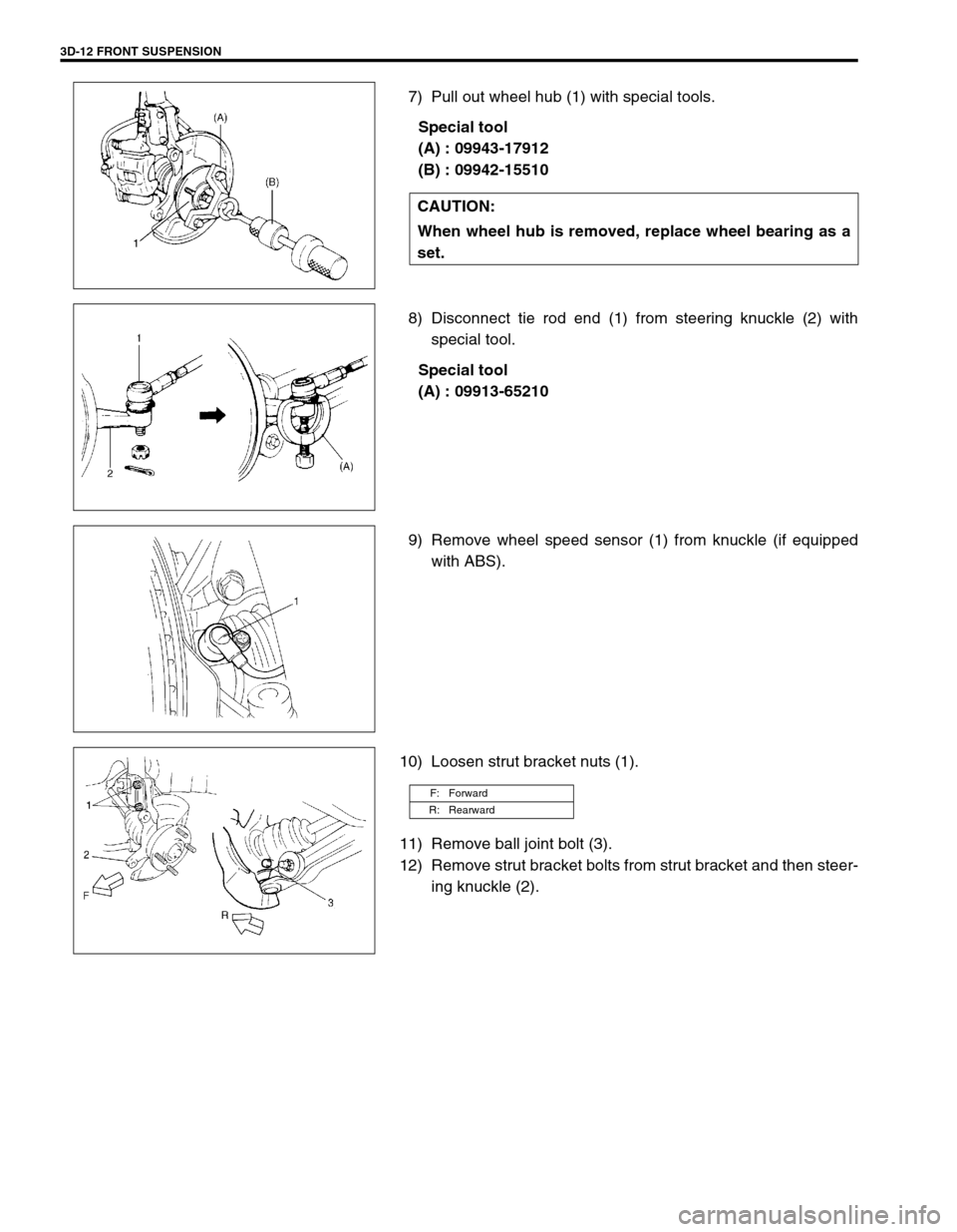
7) Pull out wheel hub (1) with special tools.
Special tool
(A) : 09943-17912
(B) : 09942-15510
8) Disconnect tie rod end (1) from steering knuckle (2) with
special tool.
Special tool
(A) : 09913-65210
9) Remove wheel speed sensor (1) from knuckle (if equipped
with ABS).
10) Loosen strut bracket nuts (1).
11) Remove ball joint bolt (3).
12) Remove strut bracket bolts from strut bracket and then steer-
ing knuckle (2). CAUTION:
When wheel hub is removed, replace wheel bearing as a
set.
F: Forward
R: Rearward
Page 208 of 698
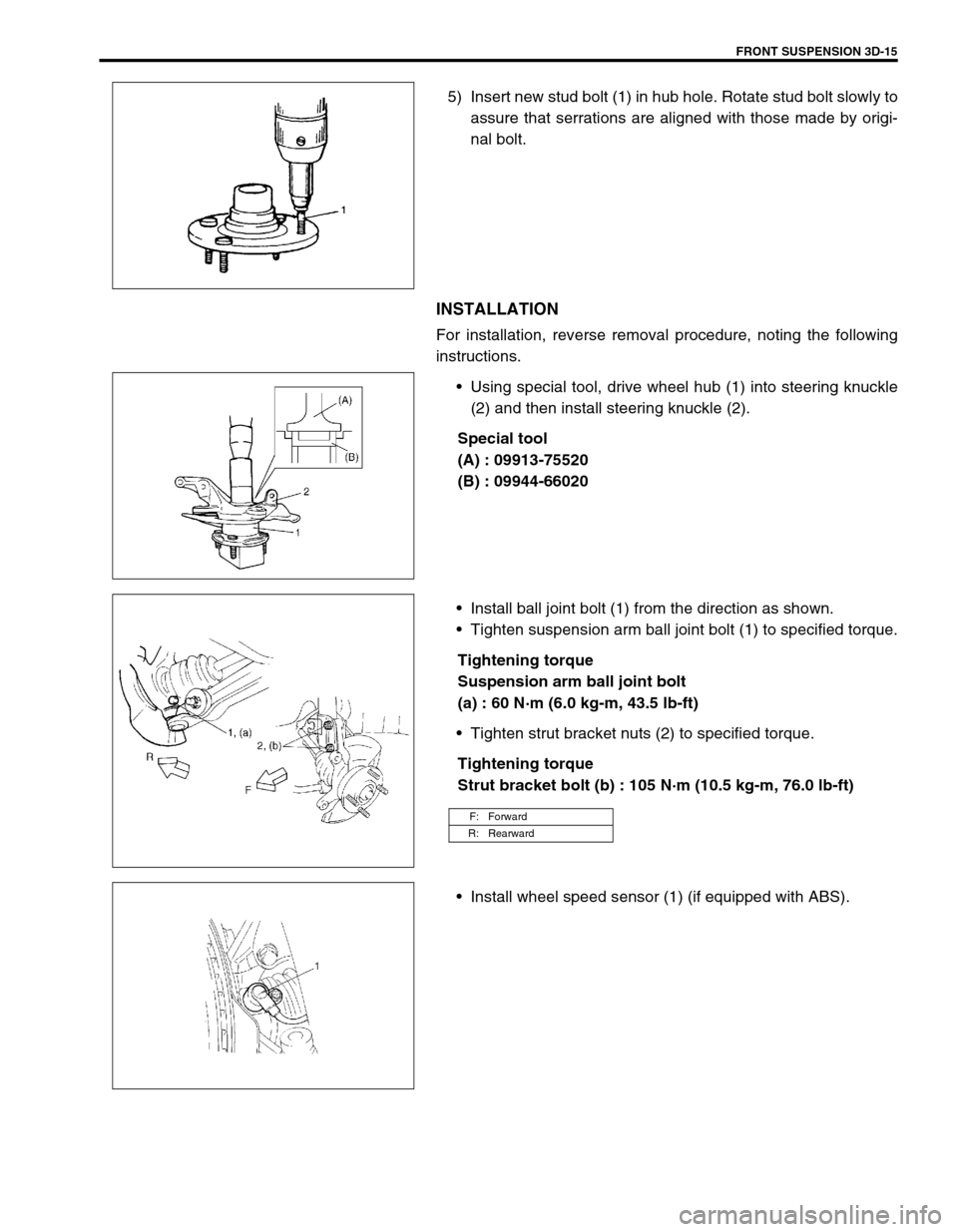
FRONT SUSPENSION 3D-15
5) Insert new stud bolt (1) in hub hole. Rotate stud bolt slowly to
assure that serrations are aligned with those made by origi-
nal bolt.
INSTALLATION
For installation, reverse removal procedure, noting the following
instructions.
Using special tool, drive wheel hub (1) into steering knuckle
(2) and then install steering knuckle (2).
Special tool
(A) : 09913-75520
(B) : 09944-66020
Install ball joint bolt (1) from the direction as shown.
Tighten suspension arm ball joint bolt (1) to specified torque.
Tightening torque
Suspension arm ball joint bolt
(a) : 60 N·m (6.0 kg-m, 43.5 lb-ft)
Tighten strut bracket nuts (2) to specified torque.
Tightening torque
Strut bracket bolt (b) : 105 N·m (10.5 kg-m, 76.0 lb-ft)
Install wheel speed sensor (1) (if equipped with ABS).
F: Forward
R: Rearward
Page 209 of 698

3D-16 FRONT SUSPENSION
Connect tie rod end (1) to steering knuckle (2) and tighten tie
rod end castle nut (3) to specified torque.
Tightening torque
The rod end castle nut (a) : 43 N·m (4.3 kg-m, 31.5 lb-ft)
Install new split pin (4).
Install brake disc (2) and brake caliper (3).
Tighten brake caliper bolt to specified torque.
Tightening torque
Brake caliper bolt : 85 N·m (8.5 kg-m, 61.5 lb-ft)
Depress foot brake pedal and hold it there.
Tighten new drive shaft nut (1) to specified torque.
Tightening torque
Drive shaft nut (a) : 175 N·m (17.5 kg-m, 127.0 lb-ft)
Caulk drive shaft nut (1) as shown.
Caulking specification
“a” : 0.5 mm (0.02 in.) or more
Tightening wheel nut to specified torque.
Tightening torque
Wheel nut : 85 N·m (8.5 kg-m, 61.5 lb-ft)
SUSPENSION CONTROL ARM / BUSHING
REMOVAL
1) Remove stabilizer bar. Refer to “STABILIZER BAR AND/OR
BUSHINGS” in this section.
2) Remove suspension control arm ball joint bolt (1).
CAUTION:
Never reuse drive shaft nut (1).
CAUTION:
Be careful while caulking nut so that no crack will occur
in caulked part of nut. Cracked nut must be replaced with
new one.
F: Forward
Page 211 of 698

3D-18 FRONT SUSPENSION
2) Press-fit bushing so that dimensions “A” and “B” in figure
become equal.
INSTALLATION
1) Install body side of suspension control arm but tighten sus-
pension control arm bolt (1) only temporarily.
2) Install suspension control arm ball joint to steering knuckle.
Align ball stud groove with steering knuckle bolt hole. Then
install ball joint bolt (1) from the direction as shown in figure.
Tighten suspension arm ball joint bolt (1) to specified torque.
Tightening torque
Suspension arm ball joint bolt
(a) : 60 N·m (6.0 kg-m, 43.5 lb-ft)
3) Install stabilizer bar, referring to “STABILIZER BAR AND/OR
BUSHINGS” in this section.
4) Lower hoist and vehicle in non-loaded condition, tighten con-
trol arm bolt (1) to specified torque.
Tightening torque
Control arm bolt (a) : 60 N·m (6.0 kg-m, 43.5 lb-ft)
5) Confirm front end (wheel) alignment referring to Section 3A.
F: Forward