wheel SUZUKI SWIFT 2000 1.G RG413 Service Workshop Manual
[x] Cancel search | Manufacturer: SUZUKI, Model Year: 2000, Model line: SWIFT, Model: SUZUKI SWIFT 2000 1.GPages: 698, PDF Size: 16.01 MB
Page 300 of 698
BRAKES 5-27
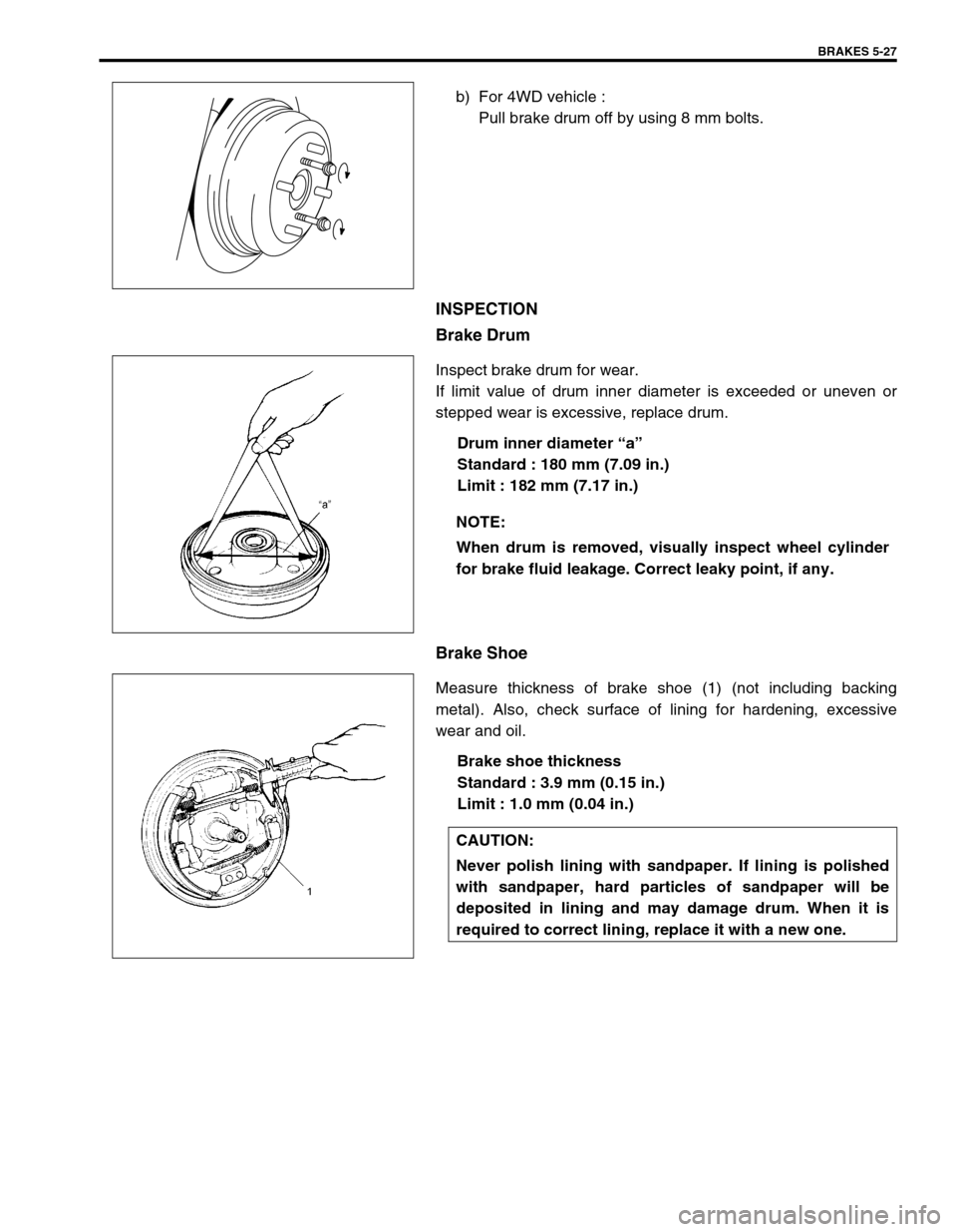
b) For 4WD vehicle :
Pull brake drum off by using 8 mm bolts.
INSPECTION
Brake Drum
Inspect brake drum for wear.
If limit value of drum inner diameter is exceeded or uneven or
stepped wear is excessive, replace drum.
Drum inner diameter “a”
Standard : 180 mm (7.09 in.)
Limit : 182 mm (7.17 in.)
Brake Shoe
Measure thickness of brake shoe (1) (not including backing
metal). Also, check surface of lining for hardening, excessive
wear and oil.
Brake shoe thickness
Standard : 3.9 mm (0.15 in.)
Limit : 1.0 mm (0.04 in.)
NOTE:
When drum is removed, visually inspect wheel cylinder
for brake fluid leakage. Correct leaky point, if any.
CAUTION:
Never polish lining with sandpaper. If lining is polished
with sandpaper, hard particles of sandpaper will be
deposited in lining and may damage drum. When it is
required to correct lining, replace it with a new one.
Page 301 of 698
5-28 BRAKES
INSTALLATION
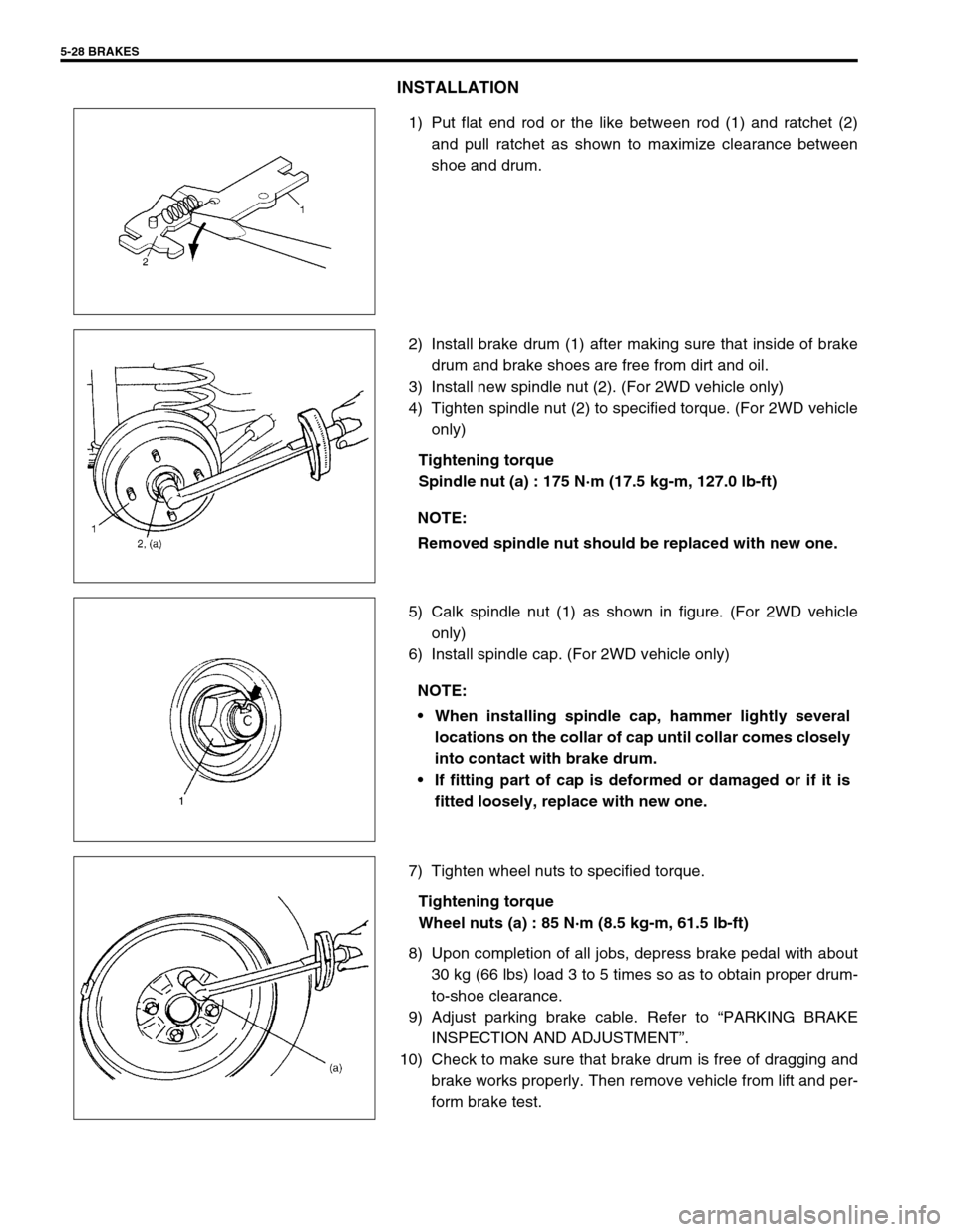
1) Put flat end rod or the like between rod (1) and ratchet (2)
and pull ratchet as shown to maximize clearance between
shoe and drum.
2) Install brake drum (1) after making sure that inside of brake
drum and brake shoes are free from dirt and oil.
3) Install new spindle nut (2). (For 2WD vehicle only)
4) Tighten spindle nut (2) to specified torque. (For 2WD vehicle
only)
Tightening torque
Spindle nut (a) : 175 N·m (17.5 kg-m, 127.0 lb-ft)
5) Calk spindle nut (1) as shown in figure. (For 2WD vehicle
only)
6) Install spindle cap. (For 2WD vehicle only)
7) Tighten wheel nuts to specified torque.
Tightening torque
Wheel nuts (a) : 85 N·m (8.5 kg-m, 61.5 lb-ft)
8) Upon completion of all jobs, depress brake pedal with about
30 kg (66 lbs) load 3 to 5 times so as to obtain proper drum-
to-shoe clearance.
9) Adjust parking brake cable. Refer to “PARKING BRAKE
INSPECTION AND ADJUSTMENT”.
10) Check to make sure that brake drum is free of dragging and
brake works properly. Then remove vehicle from lift and per-
form brake test.
NOTE:
Removed spindle nut should be replaced with new one.
NOTE:
When installing spindle cap, hammer lightly several
locations on the collar of cap until collar comes closely
into contact with brake drum.
If fitting part of cap is deformed or damaged or if it is
fitted loosely, replace with new one.
Page 303 of 698
5-30 BRAKES
INSTALLATION
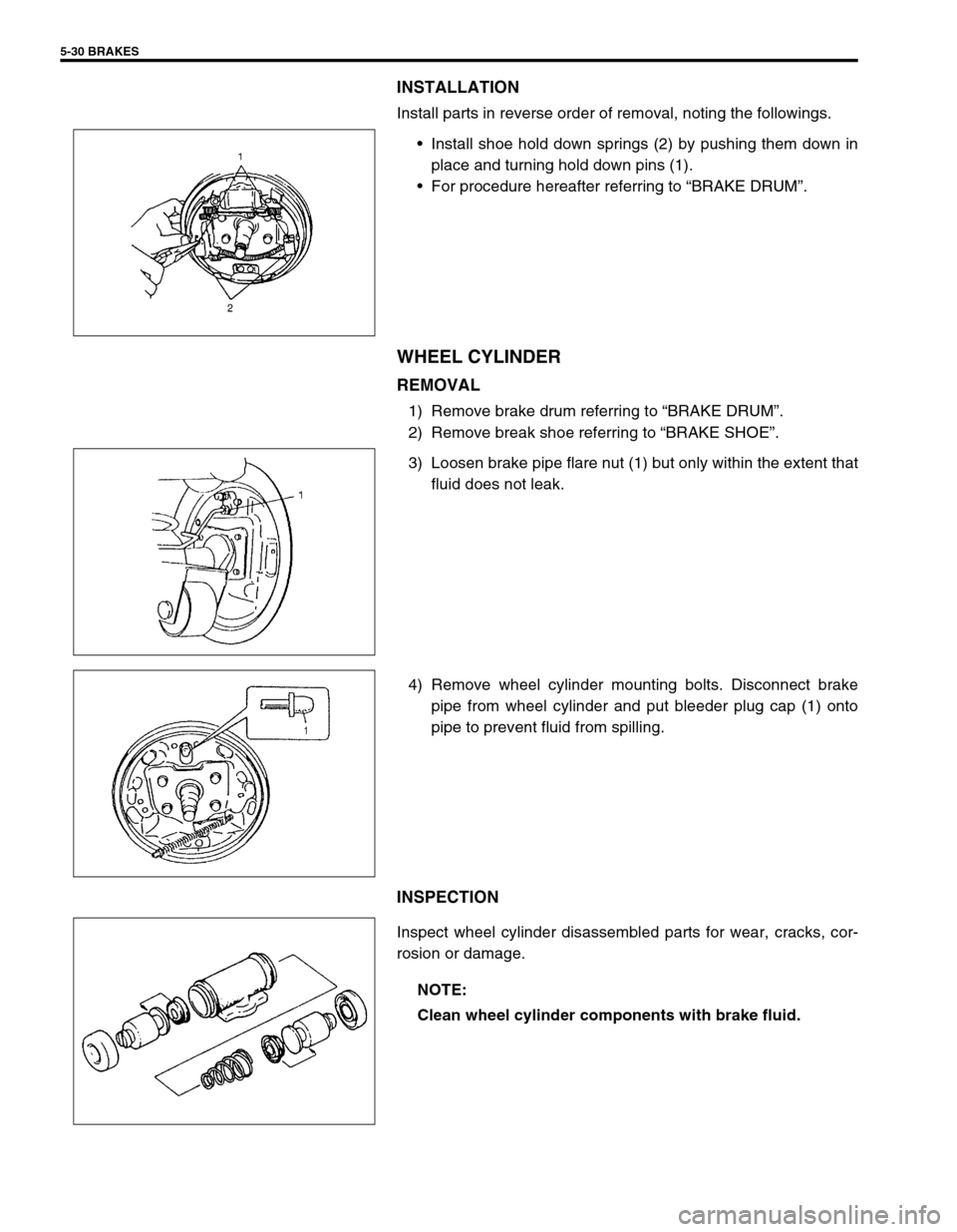
Install parts in reverse order of removal, noting the followings.
Install shoe hold down springs (2) by pushing them down in
place and turning hold down pins (1).
For procedure hereafter referring to “BRAKE DRUM”.
WHEEL CYLINDER
REMOVAL
1) Remove brake drum referring to “BRAKE DRUM”.
2) Remove break shoe referring to “BRAKE SHOE”.
3) Loosen brake pipe flare nut (1) but only within the extent that
fluid does not leak.
4) Remove wheel cylinder mounting bolts. Disconnect brake
pipe from wheel cylinder and put bleeder plug cap (1) onto
pipe to prevent fluid from spilling.
INSPECTION
Inspect wheel cylinder disassembled parts for wear, cracks, cor-
rosion or damage.
NOTE:
Clean wheel cylinder components with brake fluid.
Page 304 of 698
BRAKES 5-31
INSTALLATION
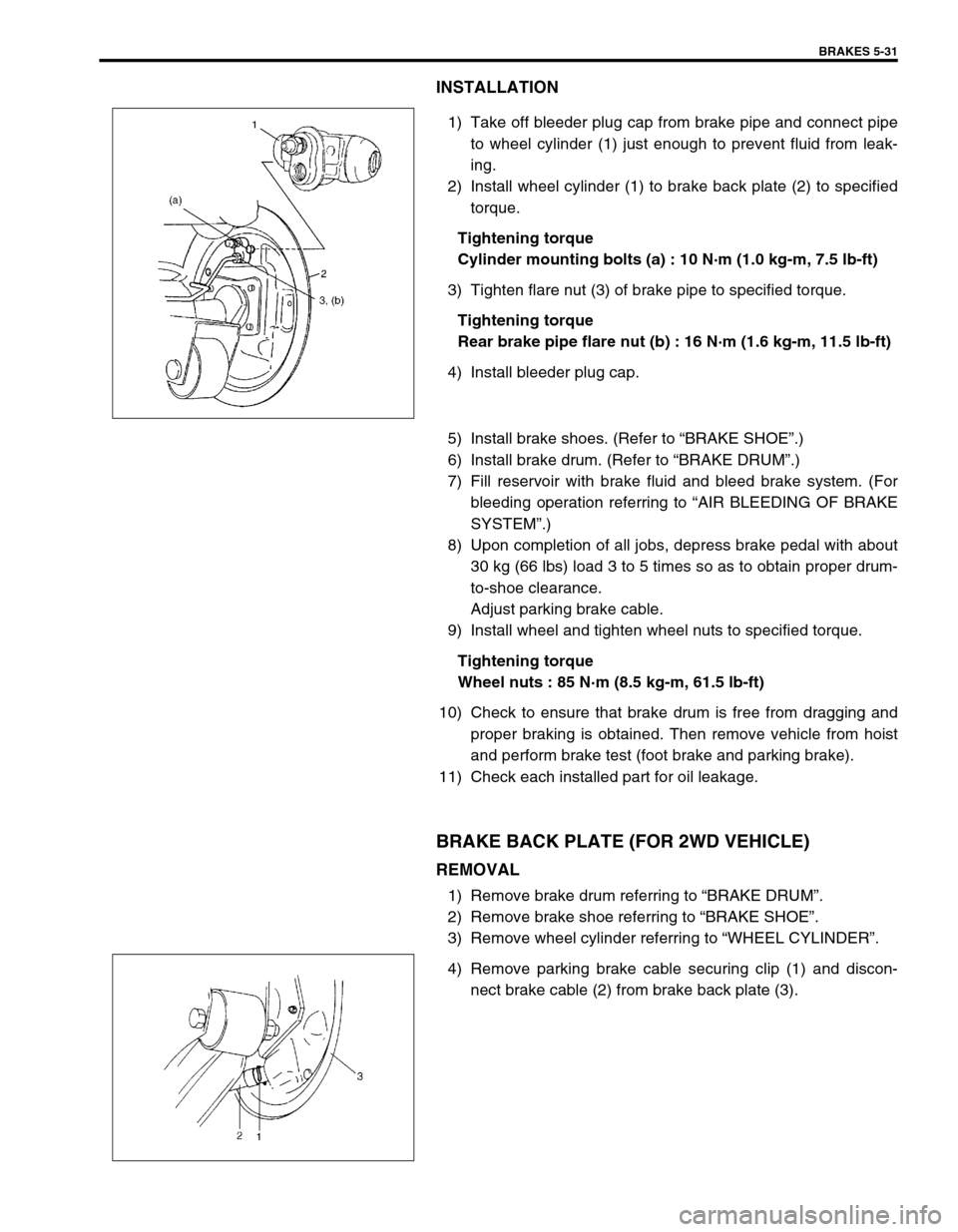
1) Take off bleeder plug cap from brake pipe and connect pipe
to wheel cylinder (1) just enough to prevent fluid from leak-
ing.
2) Install wheel cylinder (1) to brake back plate (2) to specified
torque.
Tightening torque
Cylinder mounting bolts (a) : 10 N·m (1.0 kg-m, 7.5 lb-ft)
3) Tighten flare nut (3) of brake pipe to specified torque.
Tightening torque
Rear brake pipe flare nut (b) : 16 N·m (1.6 kg-m, 11.5 lb-ft)
4) Install bleeder plug cap.
5) Install brake shoes. (Refer to “BRAKE SHOE”.)
6) Install brake drum. (Refer to “BRAKE DRUM”.)
7) Fill reservoir with brake fluid and bleed brake system. (For
bleeding operation referring to “AIR BLEEDING OF BRAKE
SYSTEM”.)
8) Upon completion of all jobs, depress brake pedal with about
30 kg (66 lbs) load 3 to 5 times so as to obtain proper drum-
to-shoe clearance.
Adjust parking brake cable.
9) Install wheel and tighten wheel nuts to specified torque.
Tightening torque
Wheel nuts : 85 N·m (8.5 kg-m, 61.5 lb-ft)
10) Check to ensure that brake drum is free from dragging and
proper braking is obtained. Then remove vehicle from hoist
and perform brake test (foot brake and parking brake).
11) Check each installed part for oil leakage.
BRAKE BACK PLATE (FOR 2WD VEHICLE)
REMOVAL
1) Remove brake drum referring to “BRAKE DRUM”.
2) Remove brake shoe referring to “BRAKE SHOE”.
3) Remove wheel cylinder referring to “WHEEL CYLINDER”.
4) Remove parking brake cable securing clip (1) and discon-
nect brake cable (2) from brake back plate (3).
Page 305 of 698
5-32 BRAKES
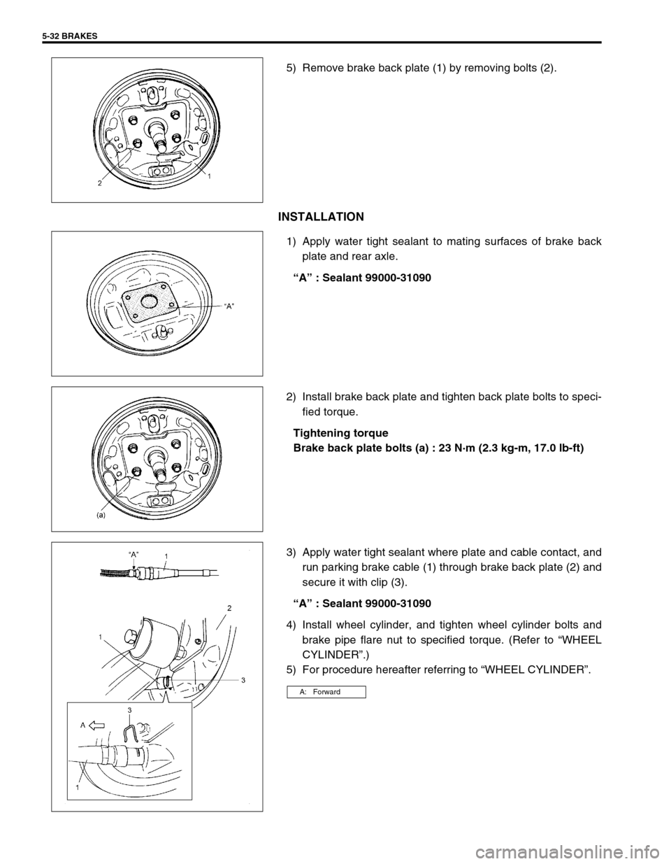
5) Remove brake back plate (1) by removing bolts (2).
INSTALLATION
1) Apply water tight sealant to mating surfaces of brake back
plate and rear axle.
“A” : Sealant 99000-31090
2) Install brake back plate and tighten back plate bolts to speci-
fied torque.
Tightening torque
Brake back plate bolts (a) : 23 N·m (2.3 kg-m, 17.0 lb-ft)
3) Apply water tight sealant where plate and cable contact, and
run parking brake cable (1) through brake back plate (2) and
secure it with clip (3).
“A” : Sealant 99000-31090
4) Install wheel cylinder, and tighten wheel cylinder bolts and
brake pipe flare nut to specified torque. (Refer to “WHEEL
CYLINDER”.)
5) For procedure hereafter referring to “WHEEL CYLINDER”.
A: Forward
Page 306 of 698
BRAKES 5-33
BRAKE BACK PLATE (FOR 4WD VEHICLE)
REMOVAL AND INSTALLATION
Refer to “REAR AXLE SHAFT AND WHEEL BEARING (4WD VEHICLE)” in Section 3E.
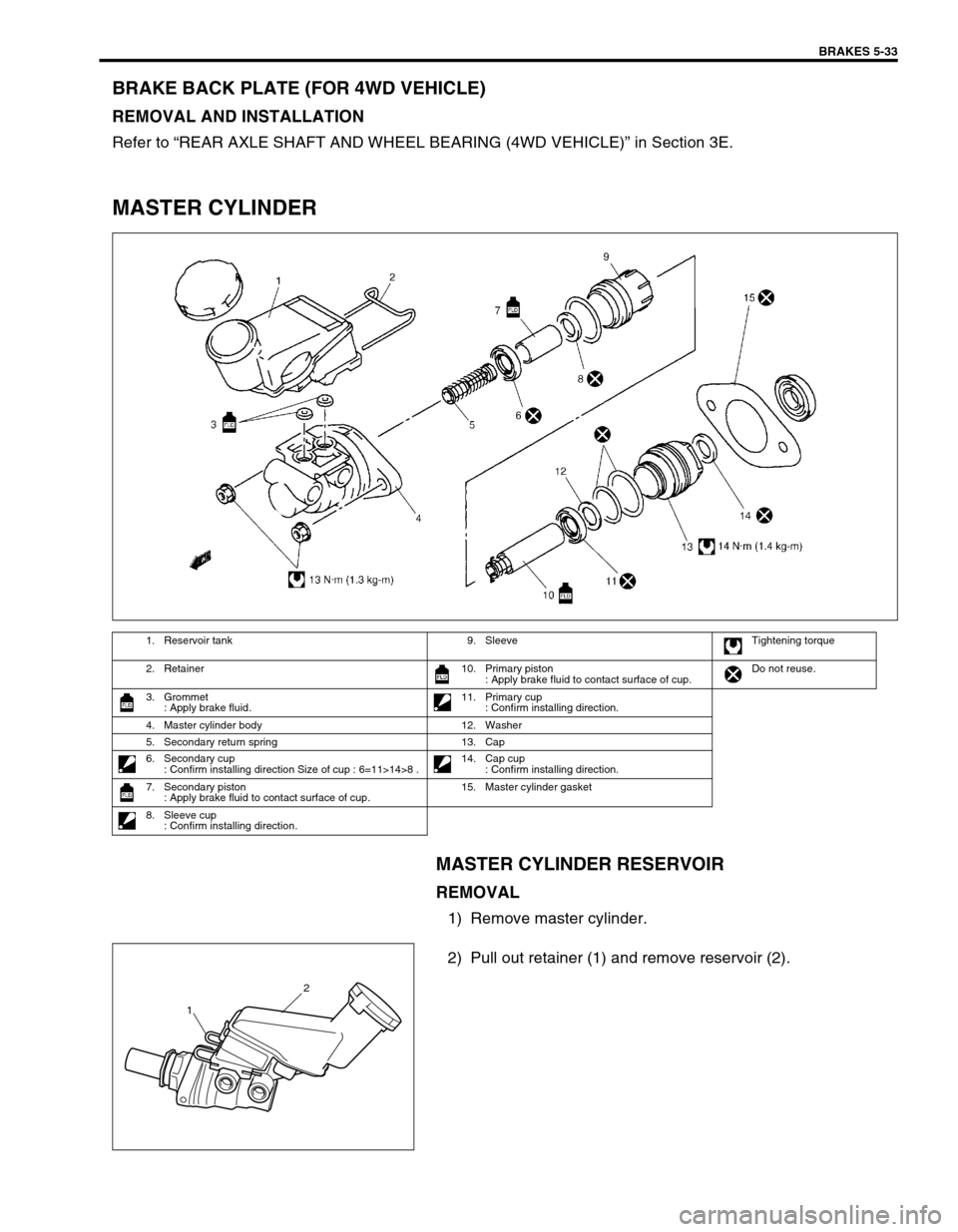
MASTER CYLINDER
MASTER CYLINDER RESERVOIR
REMOVAL
1) Remove master cylinder.
2) Pull out retainer (1) and remove reservoir (2).
1. Reservoir tank 9. Sleeve Tightening torque
2. Retainer 10. Primary piston
: Apply brake fluid to contact surface of cup.Do not reuse.
3. Grommet
: Apply brake fluid.11. Primary cup
: Confirm installing direction.
4. Master cylinder body 12. Washer
5. Secondary return spring 13. Cap
6. Secondary cup
: Confirm installing direction Size of cup : 6=11>14>8 .14. Cap cup
: Confirm installing direction.
7. Secondary piston
: Apply brake fluid to contact surface of cup.15. Master cylinder gasket
8. Sleeve cup
: Confirm installing direction.
2
1
Page 314 of 698
BRAKES 5-41
BRAKE HOSE/PIPE
FRONT BRAKE HOSE/PIPE
REMOVAL
1) Raise and support vehicle properly. Remove tire and wheel.
2) Clean dirt and foreign material from both flexible hose end and pipe end fittings.
3) Remove brake flexible hose or pipe.
INSTALLATION
Reverse brake flexible hose installation procedure, noting the followings.
Make sure that steering wheel is in straight-forward position and flexible hose has not twist or kink.
Check to make sure that flexible hose doesn’t contact any part of suspension, both in extreme right and
extreme left turn conditions. If it does at any point, remove and correct. Fill and maintain brake fluid level in
reservoir.
Bleed brake system. Refer to “AIR BLEEDING OF BRAKE SYSTEM”.
Perform brake test and check installed part for fluid leakage. NOTE:
This operation is not necessary when removing pipes connecting master cylinder.
Page 317 of 698
5-44 BRAKES
REAR BRAKE HOSE/PIPE
REMOVAL
1) Raise and support vehicle properly. Remove tire and wheel.
2) Clean dirt and foreign material from both flexible hose end and pipe end fittings.
3) Remove brake flexible hose or pipe.
INSTALLATION
Reverse brake flexible hose installation procedure, nothing the followings.
Fill and maintain brake fluid level in reservoir.
Bleed brake system. Refer to “AIR BLEEDING OF BRAKE SYSTEM”.
Perform brake test and check each installed part for fluid leakage.
Never reuse protector nut once removed. Be sure to use a new one.
Install clamps properly referring to figure below and tighten bolts.
When installing hose, make sure that it has no twist or kink.
Page 319 of 698
5-46 BRAKES
PARKING BRAKE CABLE
REMOVAL
1) Raise, suitably support vehicle and remove wheel.
2) Remove parking brake cable.
INSTALLATION
Install it by reversing removal procedure, noting the following points.
Install clamps properly referring to figure below.
Tighten bolts and nuts to specified torque.
Adjust parking brake cable. (Refer to “PARKING BRAKE INSPECTION AND ADJUSTMENT”.)
Check brake drum for dragging and brake system for proper performance. After removing vehicle from hoist,
brake test should be performed.
Page 323 of 698

5-50 BRAKES
REQUIRED SERVICE MATERIAL
SPECIAL TOOL
MaterialRecommended SUZUKI product
(Part Number)Use
Brake fluid DOT 3 or SAE J1703To fill master cylinder reservoir.
To clean and apply to inner parts of master
cylinder caliper and wheel cylinder when they
are disassembled.
Water tight sealant SEALING COMPOUND 366E
(99000-31090)To apply to mating surfaces of brake back
plate and rear axle (2WD vehicle) or rear
axle housing (4WD vehicle).
To apply to mating surfaces of brake back
plate and parking brake cable.
Lithium grease SUZUKI SUPER GREASE A
(99000-25010)To apply to slide pin of brake caliper carrier.
09900-06106 09900-20606 09900-20701 09942-15510
Snap ring remover Dial gauge Dial gauge chuck Sliding hammer
09943-17912 09951-18220 09952-16020 09952-46010
Brake drum remover
(Front wheel hub
remover)Secondary cup installer
setBooster piston rod
adjusterMaster cylinder attach-
ment