Rpm SUZUKI SWIFT 2000 1.G RG413 Service User Guide
[x] Cancel search | Manufacturer: SUZUKI, Model Year: 2000, Model line: SWIFT, Model: SUZUKI SWIFT 2000 1.GPages: 698, PDF Size: 16.01 MB
Page 680 of 698

6G-8 CRANKING SYSTEM
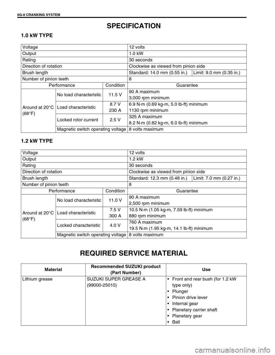
SPECIFICATION
1.0 kW TYPE
1.2 kW TYPE
REQUIRED SERVICE MATERIAL
Voltage 12 volts
Output 1.0 kW
Rating 30 seconds
Direction of rotation Clockwise as viewed from pinion side
Brush length Standard: 14.0 mm (0.55 in.) Limit: 9.0 mm (0.35 in.)
Number of pinion teeth 8
Performance Condition Guarantee
Around at 20°C
(68°F)No load characteristic 11.5 V90 A maximum
3,000 rpm minimum
Load characteristic8.7 V
230 A6.9 N·m (0.69 kg-m, 5.0 lb-ft) minimum
1130 rpm minimum
Locked rotor current 2.5 V325 A maximum
8.2 N·m (0.82 kg-m, 6.0 lb-ft) minimum
Magnetic switch operating voltage 8 volts maximum
Voltage 12 volts
Output 1.2 kW
Rating 30 seconds
Direction of rotation Clockwise as viewed from pinion side
Brush length Standard: 12.3 mm (0.48 in.) Limit: 7.0 mm (0.27 in.)
Number of pinion teeth 8
Performance Condition Guarantee
Around at 20°C
(68°F)No load characteristic 11.0 V90 A maximum
2,500 rpm minimum
Load characteristic7.5 V
300 A10.5 N·m (1.05 kg-m, 7.59 lb-ft) minimum
880 rpm minimum
Locked characteristic 4.0 V760 A maximum
19.5 N·m (1.95 kg-m, 14.1 lb-ft) minimum
Magnetic switch operating voltage 8 volts maximum
MaterialRecommended SUZUKI product
(Part Number)Use
Lithium grease SUZUKI SUPER GREASE A
(99000-25010)Front and rear bush (for 1.2 kW
type only)
Plunger
Pinion drive lever
Internal gear
Planetary carrier shaft
Planetary gear
Ball
Page 683 of 698

CHARGING SYSTEM 6H-3
CARE OF BATTERY
1) The battery is a very reliable component, but needs periodical attentions.
Keep the battery carrier clean
Prevent rust formation on the terminal posts
Keep the electrolyte up to the upper level uniformly in all cells.
When keeping battery on vehicle over a long period of time, follow instructions given below.
–Weekly, start the engine and run it until it reaches normal operating temperature with engine speed of
2000 to 3000 rpm. Make sure all electric switches are off before storing the vehicle.
–Recharge the battery twice a month to prevent it from discharging excessively. This is especially impor-
tant when ambient temperature is low.
The battery discharges even when it is not used, while vehicles are being stored. Battery electrolyte can
freeze and battery case can crack at cold ambient condition if battery is not properly charged.
2) Keep the battery cable connections clean.
The cable connections, particularly at the positive (+) terminal post, tend to become corroded. The product
of corrosion, or rust, on the mating faces of conductors resists the flow of current.
Clean the terminals and fittings periodically to ensure good metal-to-metal contact, and grease the connec-
tions after each cleaning to protect them against rusting.
3) Be always in the know as to the state of charge of the battery. The simplest way to tell the state of charge is
to carry out a hydrometer test. The hydrometer is an instrument for measuring the specific gravity (S.G.) of
the battery electrolyte. The S.G. of the electrolyte is indicative of the state of charge. Refer to “DIAGNOSIS”
of BATTERY in this section. WARNING:
Never expose battery to open flame or electric spark because of battery generate gas which is flam-
mable and explosive.
Do not allow battery fluid to contact eyes, skin, fabrics, or painted surfaces as fluid is a corrosive
acid. Flush any contacted area with water immediately and thoroughly.
Batteries should always be kept out of reach of children.
Page 687 of 698

CHARGING SYSTEM 6H-7
UNDERCHARGED BATTERY
This condition, as evidenced by slow cranking or indicator clear
with red dot can be caused by one or more of the following condi-
tions even though indicator lamp may be operating normal.
Following procedure also applies to cars with voltmeter and
ammeter.
Make sure that undercharged condition has not been caused
by accessories left on for extended period of time.
Check drive belt for proper tension.
If battery defect is suspected, refer to BATTERY section.
Inspect wiring for defects. Check all connections for tight-
ness and cleanliness, battery cable connections at battery,
starting motor and ignition ground cable.
NO-LOAD CHECK
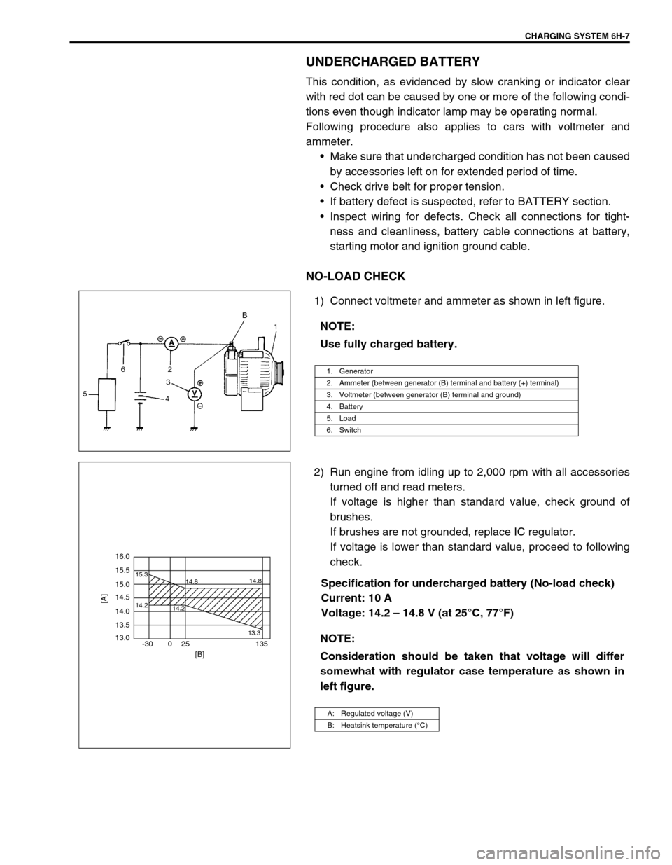
1) Connect voltmeter and ammeter as shown in left figure.
2) Run engine from idling up to 2,000 rpm with all accessories
turned off and read meters.
If voltage is higher than standard value, check ground of
brushes.
If brushes are not grounded, replace IC regulator.
If voltage is lower than standard value, proceed to following
check.
Specification for undercharged battery (No-load check)
Current: 10 A
Voltage: 14.2 – 14.8 V (at 25°C, 77°F) NOTE:
Use fully charged battery.
1. Generator
2. Ammeter (between generator (B) terminal and battery (+) terminal)
3. Voltmeter (between generator (B) terminal and ground)
4. Battery
5. Load
6. Switch
NOTE:
Consideration should be taken that voltage will differ
somewhat with regulator case temperature as shown in
left figure.
A: Regulated voltage (V)
B: Heatsink temperature (°C)
16.0
15.5
14.2 15.3
14.8
14.2
13.314.8
15.0
14.5
14.0
13.5
13.0
-30 0 25 135
[A]
[B]
Page 688 of 698

6H-8 CHARGING SYSTEM
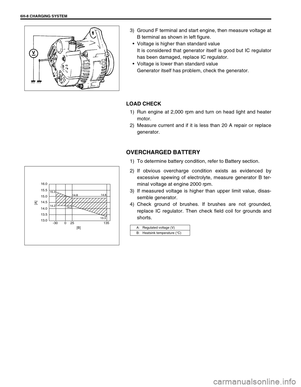
3) Ground F terminal and start engine, then measure voltage at
B terminal as shown in left figure.
Voltage is higher than standard value
It is considered that generator itself is good but IC regulator
has been damaged, replace IC regulator.
Voltage is lower than standard value
Generator itself has problem, check the generator.
LOAD CHECK
1) Run engine at 2,000 rpm and turn on head light and heater
motor.
2) Measure current and if it is less than 20 A repair or replace
generator.
OVERCHARGED BATTERY
1) To determine battery condition, refer to Battery section.
2) If obvious overcharge condition exists as evidenced by
excessive spewing of electrolyte, measure generator B ter-
minal voltage at engine 2000 rpm.
3) If measured voltage is higher than upper limit value, disas-
semble generator.
4) Check ground of brushes. If brushes are not grounded,
replace IC regulator. Then check field coil for grounds and
shorts.
A: Regulated voltage (V)
B: Heatsink temperature (°C)
16.0
15.5
14.2 15.3
14.8
14.2
13.314.8
15.0
14.5
14.0
13.5
13.0
-30 0 25 135
[A]
[B]
Page 694 of 698

6H-14 CHARGING SYSTEM
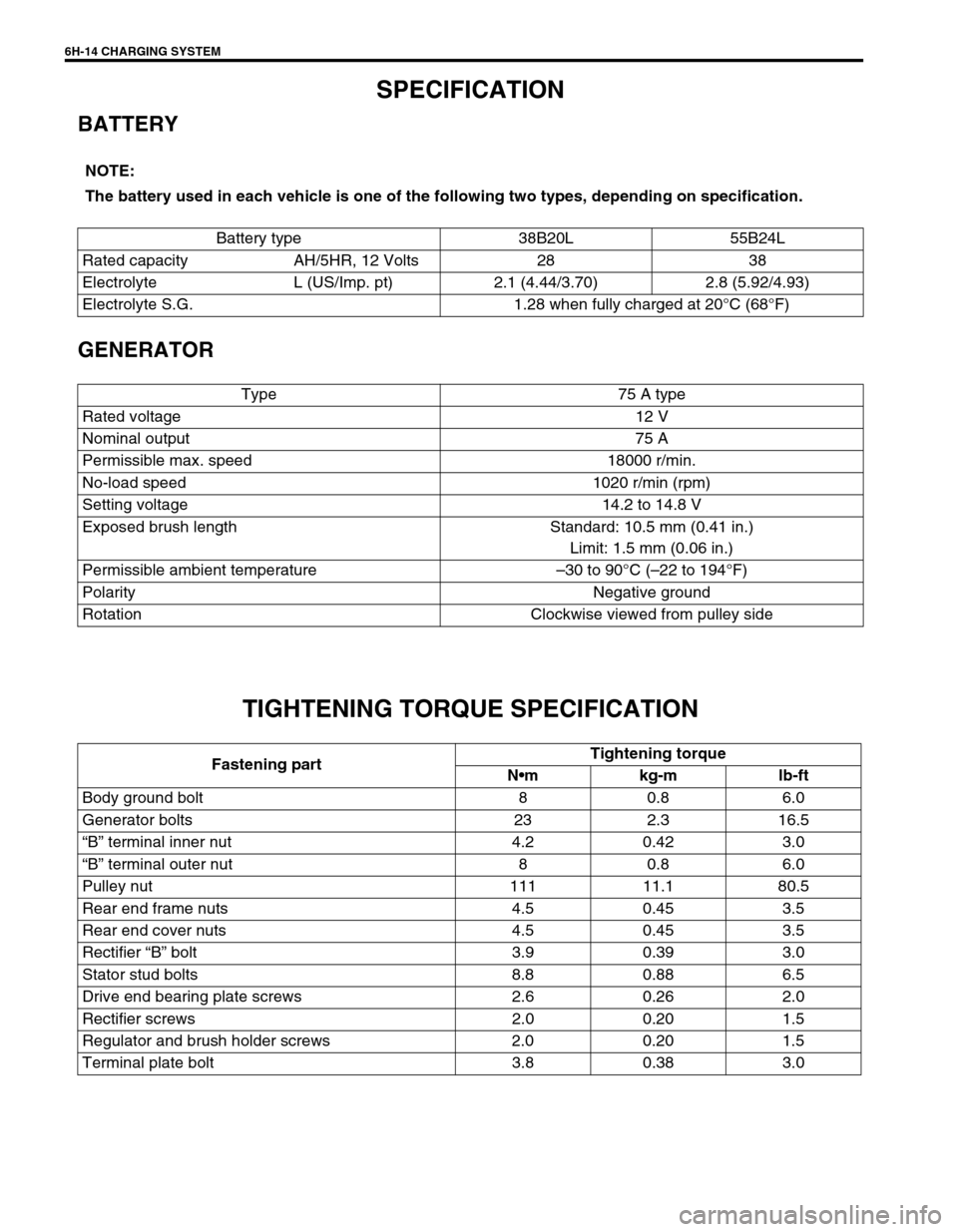
SPECIFICATION
BATTERY
GENERATOR
TIGHTENING TORQUE SPECIFICATION
NOTE:
The battery used in each vehicle is one of the following two types, depending on specification.
Battery type 38B20L 55B24L
Rated capacity AH/5HR, 12 Volts 28 38
Electrolyte L (US/Imp. pt) 2.1 (4.44/3.70) 2.8 (5.92/4.93)
Electrolyte S.G. 1.28 when fully charged at 20°C (68°F)
Type 75 A type
Rated voltage 12 V
Nominal output 75 A
Permissible max. speed 18000 r/min.
No-load speed 1020 r/min (rpm)
Setting voltage 14.2 to 14.8 V
Exposed brush length Standard: 10.5 mm (0.41 in.)
Limit: 1.5 mm (0.06 in.)
Permissible ambient temperature–30 to 90°C (–22 to 194°F)
Polarity Negative ground
Rotation Clockwise viewed from pulley side
Fastening partTightening torque
Nm kg-m lb-ft
Body ground bolt 8 0.8 6.0
Generator bolts 23 2.3 16.5
“B” terminal inner nut 4.2 0.42 3.0
“B” terminal outer nut 8 0.8 6.0
Pulley nut 111 11.1 80.5
Rear end frame nuts 4.5 0.45 3.5
Rear end cover nuts 4.5 0.45 3.5
Rectifier “B” bolt 3.9 0.39 3.0
Stator stud bolts 8.8 0.88 6.5
Drive end bearing plate screws 2.6 0.26 2.0
Rectifier screws 2.0 0.20 1.5
Regulator and brush holder screws 2.0 0.20 1.5
Terminal plate bolt 3.8 0.38 3.0