automatic transmission SUZUKI SWIFT 2000 1.G RG413 Service User Guide
[x] Cancel search | Manufacturer: SUZUKI, Model Year: 2000, Model line: SWIFT, Model: SUZUKI SWIFT 2000 1.GPages: 698, PDF Size: 16.01 MB
Page 290 of 698

BRAKES 5-17
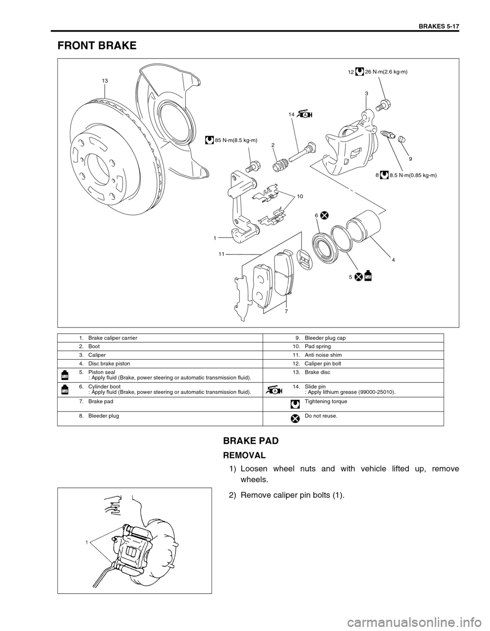
FRONT BRAKE
BRAKE PAD
REMOVAL
1) Loosen wheel nuts and with vehicle lifted up, remove
wheels.
2) Remove caliper pin bolts (1).
1. Brake caliper carrier 9. Bleeder plug cap
2. Boot 10. Pad spring
3. Caliper 11. Anti noise shim
4. Disc brake piston 12. Caliper pin bolt
5. Piston seal
: Apply fluid (Brake, power steering or automatic transmission fluid).13. Brake disc
6. Cylinder boot
: Apply fluid (Brake, power steering or automatic transmission fluid).14. Slide pin
: Apply lithium grease (99000-25010).
7. Brake pad Tightening torque
8. Bleeder plugDo not reuse.
9
1
7
13
2
143
1226 N·m(2.6 kg-m)
85 N·m(8.5 kg-m)
8
8.5 N·m(0.85 kg-m)
10
5 4
6
11
Page 382 of 698

ENGINE GENERAL INFORMATION AND DIAGNOSIS 6-13
1. CUSTOMER COMPLAINT ANALYSIS
Record details of the problem (failure, complaint) and how it occurred as described by the customer. For this
purpose, use of such an inspection form will facilitate collecting information to the point required for proper anal-
ysis and diagnosis.
2. DTC/FREEZE FRAME DATA CHECK, RECORD AND CLEARANCE
First, check DTC (including pending DTC), referring to “DTC check” section. If DTC is indicated, print it and
freeze frame data or write them down and then clear them by referring to “DTC clearance” section. DTC indi-
cates malfunction that occurred in the system but does not indicate whether it exists now or it occurred in the
past and the normal condition has been restored now. To check which case applies, check the symptom in
question according to Step 4 and recheck DTC according to Step 5.
Attempt to diagnose a trouble based on DTC in this step only or failure to clear the DTC in this step will lead to
incorrect diagnosis, trouble diagnosis of a normal circuit or difficulty in troubleshooting.
3. and 4. VISUAL INSPECTION
As a preliminary step, be sure to perform visual check of the items that support proper function of the engine
referring to “Visual Inspection” section.
5. TROUBLE SYMPTOM CONFIRMATION
Based on information obtained in Step 1 Customer complaint analysis and Step 2 DTC/freeze frame data check,
confirm trouble symptoms. Also, reconfirm DTC according to “DTC Confirmation Procedure” described in each
DTC Diagnosis section.
6. and 7. RECHECKING AND RECORD OF DTC/FREEZE FRAME DATA
Refer to “DTC check” section for checking procedure.
8. ENGINE BASIC INSPECTION AND ENGINE DIAGNOSIS TABLE
Perform basic engine check according to the “Engine Basic Inspection Flow Table” first. When the end of the
flow table has been reached, check the parts of the system suspected as a possible cause referring to ENGINE
DIAGNOSIS TABLE and based on symptoms appearing on the vehicle (symptoms obtained through steps of
customer complaint analysis, trouble symptom confirmation and/or basic engine check) and repair or replace
faulty parts, if any.
9. TROUBLESHOOTING FOR DTC (See each DTC Diag. Flow Table)
Based on the DTC indicated in Step 5 and referring to the applicable DTC diag. flow table in this section, locate
the cause of the trouble, namely in a sensor, switch, wire harness, connector, actuator, ECM or other part and
repair or replace faulty parts.
10. CHECK FOR INTERMITTENT PROBLEM
Check parts where an intermittent trouble is easy to occur (e.g., wire harness, connector, etc.), referring to
“INTERMITTENT AND POOR CONNECTION” in Section 0A and related circuit of DTC recorded in Step 2.
11. FINAL CONFIRMATION TEST
Confirm that the problem symptom has gone and the engine is free from any abnormal conditions. If what has
been repaired is related to the DTC, clear the DTC once, perform DTC confirmation procedure and confirm that
no DTC is indicated.NOTE:
If only Automatic transmission DTCs (P0702-P1709) or Immobilizer DTCs (P1620-P1623) are indicated
in this step, perform trouble diagnosis according to “Diagnosis” in Section 7B or Section 8G.
Page 664 of 698

6F1-2 IGNITION SYSTEM (ELECTRONIC IGNITION SYSTEM)
GENERAL DESCRIPTION
The ignition system is an electronic (distributorless) ignition system. Its consists of the parts as described below
and has an electronic ignition control system.
ECM
It detects the engine and vehicle conditions through the signals from the sensors, determines the most suit-
able ignition timing and time for electricity to flow to the primary coil and sends a signal to the ignitor (power
unit) in the ignition coil assembly.
Ignition coil assembly (including an igniter)
The ignition coil assembly has a built-in ignitor which turns ON and OFF the current flow to the primary coil
according to the signal from ECM. When the current flow to the primary coil is turned OFF, a high voltage is
induced in the secondary coil.
High tension cords and spark plugs.
CMP sensor (Camshaft position sensor) and CKP sensor (Crankshaft position sensor)
Using signals from these sensors, ECM identifies the specific cylinder whose piston is in the compression
stroke, detects the crank angle and adjusts initial ignition timing automatically.
TP sensor, ECT sensor, MAP sensor and other sensors/switches
Refer to Section 6E1 for details.
Although this ignition system does not have a distributor, it has two ignition coil assemblies (one is for No.1 and
No.4 spark plugs and the other is for No.2 and No.3 spark plugs). When an ignition signal is sent from ECM to
the ignitor in the ignition coil assembly for No.1 and No.4 spark plugs, a high voltage is induced in the secondary
coil and that passes through the high-tension cords and causes No.1 and No.4 spark plugs to spark simulta-
neously. Likewise, when an ignition signal is sent to the ignitor in the other ignition coil assembly, No.2 and No.3
spark plugs spark simultaneously.
SYSTEM COMPONENTS
1. ECM 6. MAP sensor 11. Transmission range switch (A/T)
2. Ignition coil assembly for No.1 and No.4 spark plugs 7. ECT sensor 12. High-tension cords
3. Ignition coil assembly for No.2 and No.3 spark plugs 8. IAT sensor 13. Monitor connector
4. CMP sensor 9. TP sensor 14. Knock sensor (if equipped)
5. CKP sensor 10. VSS 15. Data link connector
Page 689 of 698

CHARGING SYSTEM 6H-9
ON-VEHICLE SERVICE
BATTERY
JUMP STARTING IN CASE OF EMERGENCY
WITH AUXILIARY (BOOSTER) BATTERY
Both booster and discharged battery should be treated carefully when using jumper cables. Follow procedure
outlined below, being careful not to cause sparks.
1) Set parking brake and place automatic transmission in PARK (NEUTRAL on manual transmission). Turn off
ignition, turn off lights and all other electrical loads.
2) Check electrolyte level. If it is below low level line, add distilled water.
3) Attach end of one jumper cable to positive terminal of booster battery and the other end of the same cable to
positive terminal of discharged battery. (Use 12-volt battery only to jump start engine).
4) Attach one end of the remaining negative cable to negative terminal of booster battery, and the other end to
a solid engine ground (such as exhaust manifold) at least 45 cm (18 in.) away from battery of vehicle being
started.
5) Start engine of vehicle with booster battery and turn off electrical accessories. Then Start engine of the vehi-
cle with discharged battery.
6) Disconnect jumper cables in the exact reverse order.
WITH CHARGING EQUIPMENT
CAUTION:
If vehicle is manual transmission model and has a catalytic converter, do not push or tow it to start.
Damage to its emission system and/or to other parts may result.
WARNING:
Departure from these conditions or procedure described below could result in:
–Serious personal injury (particularly to eyes) or property damage from such causes as battery
explosion, battery acid, or electrical burns.
–Damage to electronic components of either vehicle.
Remove rings, watches, and other jewelry. Wear approved eye protection.
Be careful so that metal tools or jumper cables do not contact positive battery terminal (or metal in
contact with it) and any other metal on vehicle, because a short circuit could occur.
WARNING:
Do not connect negative cable directly to negative terminal of dead battery.
CAUTION:
When jump starting engine with charging equipment, be sure equipment used is 12-volt and negative
ground. Do not use 24-volt charging equipment. Using such equipment can cause serious damage to
electrical system or electronic parts.