fuse box SUZUKI SWIFT 2000 1.G RG413 Service User Guide
[x] Cancel search | Manufacturer: SUZUKI, Model Year: 2000, Model line: SWIFT, Model: SUZUKI SWIFT 2000 1.GPages: 698, PDF Size: 16.01 MB
Page 160 of 698
ELECTRICAL POWER STEERING (P/S) SYSTEM 3B1-19
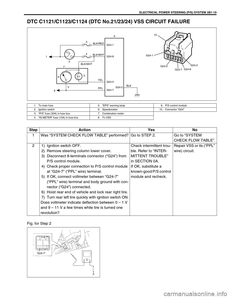
DTC C1121/C1123/C1124 (DTC No.21/23/24) VSS CIRCUIT FAILURE
Fig. for Step 2
1. To main fuse 5.“EPS” warning lamp 9. P/S control module
2. Ignition switch 6. Speedometer 10. Connector “G24”
3.“P/S” fuse (30A) in fuse box 7. Combination meter
4.“IG METER” fuse (15A) in fuse box 8. To VSS
G24-2 G24-1
G24-8
G24-7 G24-5 1
23
4
5
67
89
BLK/WHT
BLK/WHTBLK/RED
YEL
PPL VBLK
G24-1
G24-5
G24-7G24-8G24-2
10
Step Action Yes No
1Was “SYSTEM CHECK FLOW TABLE” performed? Go to STEP 2. Go to “SYSTEM
CHECK FLOW TABLE”.
2 1) Ignition switch OFF.
2) Remove steering column lower cover.
3) Disconnect 8-terminals connector (“G24”) from
P/S control module.
4) Check proper connection to P/S control module
at “G24-7” (“PPL” wire) terminal.
5) If OK, connect voltmeter between “G24-7”
(“PPL” wire) terminal and body ground with con-
nector (“G24”) connected.
6) Hoist rear end of vehicle and lock rear right tire.
7) Turn rear left tire quickly with ignition switch ON.
Does voltmeter indicate deflection between 0 – 1 V
and 9 – 11 V a few times while tire is turned one
revolution?Check intermittent trou-
ble. Refer to “INTER-
MITTENT TROUBLE”
in SECTION 0A.
If OK, substitute a
known-good P/S control
module and recheck.Repair VSS or its (“PPL”
wire) circuit.
Page 161 of 698
3B1-20 ELECTRICAL POWER STEERING (P/S) SYSTEM
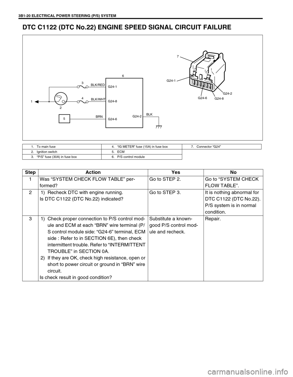
DTC C1122 (DTC No.22) ENGINE SPEED SIGNAL CIRCUIT FAILURE
1. To main fuse 4.“IG METER” fuse (15A) in fuse box 7. Connector “G24”
2. Ignition switch 5. ECM
3.“P/S” fuse (30A) in fuse box 6. P/S control module
G24-2 G24-1
G24-8
G24-6 1
23
4
56
BLK/WHT BLK/RED
BRNBLK
G24-1
G24-6
G24-8G24-2
7
Step Action Yes No
1Was “SYSTEM CHECK FLOW TABLE” per-
formed?Go to STEP 2. Go to “SYSTEM CHECK
FLOW TABLE”.
2 1) Recheck DTC with engine running.
Is DTC C1122 (DTC No.22) indicated?Go to STEP 3. It is nothing abnormal for
DTC C1122 (DTC No.22).
P/S system is in normal
condition.
3 1) Check proper connection to P/S control mod-
ule and ECM at each “BRN” wire terminal (P/
S control module side: “G24-6” terminal, ECM
side : Refer to in SECTION 6E), then check
intermittent trouble. Refer to “INTERMITTENT
TROUBLE” in SECTION 0A.
2) If they are OK, check high resistance, open or
short to power circuit or ground in “BRN” wire
circuit.
Is check result in good condition?Substitute a known-
good P/S control mod-
ule and recheck.Repair.
Page 162 of 698
ELECTRICAL POWER STEERING (P/S) SYSTEM 3B1-21
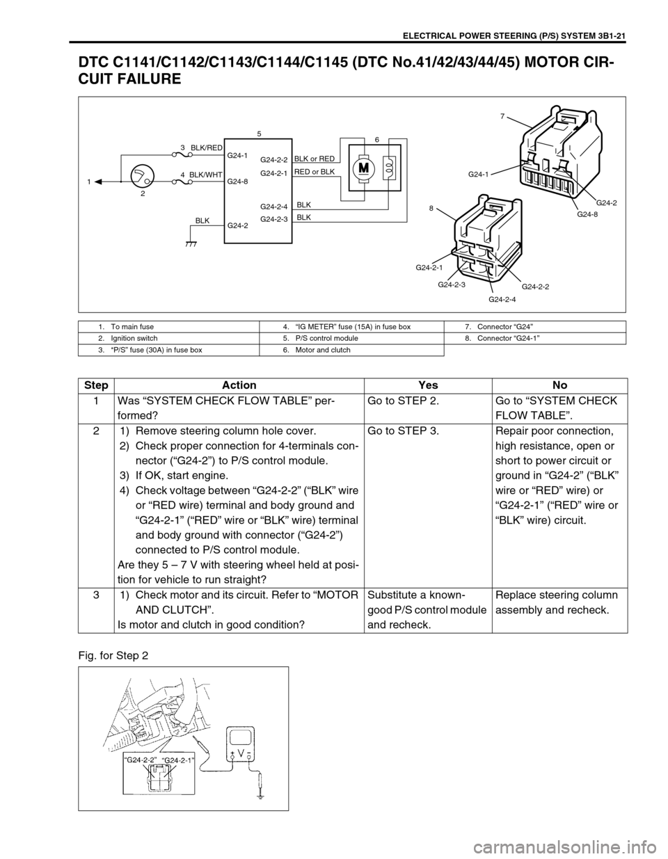
DTC C1141/C1142/C1143/C1144/C1145 (DTC No.41/42/43/44/45) MOTOR CIR-
CUIT FAILURE
Fig. for Step 2
1. To main fuse 4.“IG METER” fuse (15A) in fuse box 7. Connector “G24”
2. Ignition switch 5. P/S control module 8. Connector “G24-1”
3.“P/S” fuse (30A) in fuse box 6. Motor and clutch
MG24-1
G24-8G24-2
7
G24-2-2
G24-2-4 G24-2-3 G24-2-1
8
G24-2 G24-1
G24-8G24-2-2
G24-2-1
G24-2-4
G24-2-3 1
23
46 5
BLK/WHTBLK/RED
BLKBLK BLK RED or BLK BLK or RED
Step Action Yes No
1Was “SYSTEM CHECK FLOW TABLE” per-
formed?Go to STEP 2. Go to “SYSTEM CHECK
FLOW TABLE”.
2 1) Remove steering column hole cover.
2) Check proper connection for 4-terminals con-
nector (“G24-2”) to P/S control module.
3) If OK, start engine.
4) Check voltage between “G24-2-2” (“BLK” wire
or “RED wire) terminal and body ground and
“G24-2-1” (“RED” wire or “BLK” wire) terminal
and body ground with connector (“G24-2”)
connected to P/S control module.
Are they 5 – 7 V with steering wheel held at posi-
tion for vehicle to run straight?Go to STEP 3. Repair poor connection,
high resistance, open or
short to power circuit or
ground in “G24-2” (“BLK”
wire or “RED” wire) or
“G24-2-1” (“RED” wire or
“BLK” wire) circuit.
3 1) Check motor and its circuit. Refer to “MOTOR
AND CLUTCH”.
Is motor and clutch in good condition?Substitute a known-
good P/S control module
and recheck.Replace steering column
assembly and recheck.
Page 163 of 698
3B1-22 ELECTRICAL POWER STEERING (P/S) SYSTEM
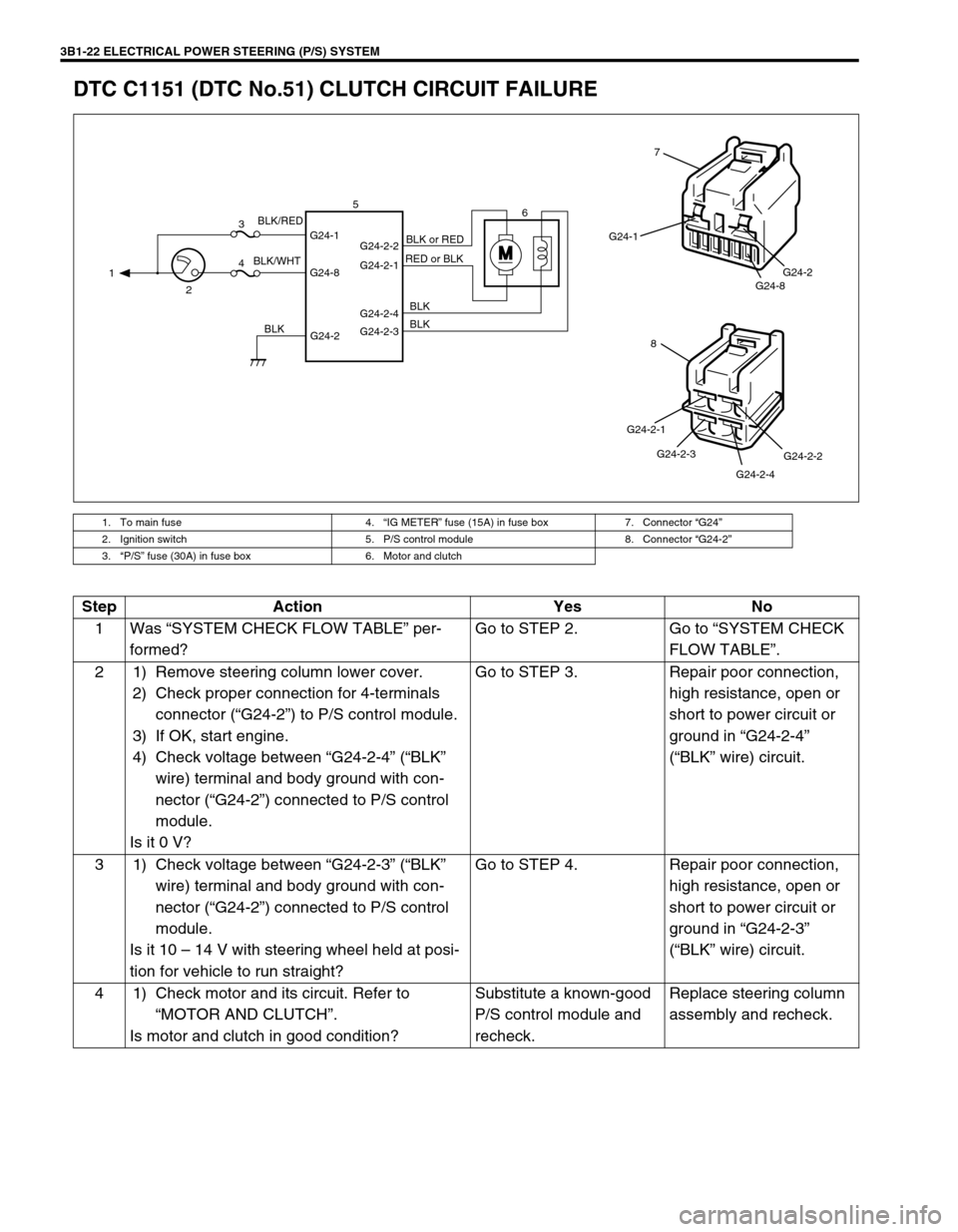
DTC C1151 (DTC No.51) CLUTCH CIRCUIT FAILURE
1. To main fuse 4.“IG METER” fuse (15A) in fuse box 7. Connector “G24”
2. Ignition switch 5. P/S control module 8. Connector “G24-2”
3.“P/S” fuse (30A) in fuse box 6. Motor and clutch
M
G24-2 G24-1
G24-8G24-2-2
G24-2-1
G24-2-4
G24-2-3 1
23
46 5
BLK/WHTBLK/RED
BLKBLK BLK RED or BLKBLK or RED
G24-1
G24-8G24-2
7
G24-2-2
G24-2-4 G24-2-3 G24-2-1
8
Step Action Yes No
1Was “SYSTEM CHECK FLOW TABLE” per-
formed?Go to STEP 2. Go to “SYSTEM CHECK
FLOW TABLE”.
2 1) Remove steering column lower cover.
2) Check proper connection for 4-terminals
connector (“G24-2”) to P/S control module.
3) If OK, start engine.
4) Check voltage between “G24-2-4” (“BLK”
wire) terminal and body ground with con-
nector (“G24-2”) connected to P/S control
module.
Is it 0 V?Go to STEP 3. Repair poor connection,
high resistance, open or
short to power circuit or
ground in “G24-2-4”
(“BLK” wire) circuit.
3 1) Check voltage between “G24-2-3” (“BLK”
wire) terminal and body ground with con-
nector (“G24-2”) connected to P/S control
module.
Is it 10 – 14 V with steering wheel held at posi-
tion for vehicle to run straight?Go to STEP 4. Repair poor connection,
high resistance, open or
short to power circuit or
ground in “G24-2-3”
(“BLK” wire) circuit.
4 1) Check motor and its circuit. Refer to
“MOTOR AND CLUTCH”.
Is motor and clutch in good condition?Substitute a known-good
P/S control module and
recheck.Replace steering column
assembly and recheck.
Page 165 of 698

3B1-24 ELECTRICAL POWER STEERING (P/S) SYSTEM
DTC C1153(DTC No.53) P/S CONTROL MODULE POWER SUPPLY CIRCUIT
FAILURE
Fig. for Step 2
DTC C1152/C1154/C1155 (DTC No.52/54/55) P/S CONTROL MODULE FAILURE
Substitute a known-good P/S control module and recheck.
1. To main fuse 3.“P/S” fuse (30A) in fuse box 5. P/S control module
2. Ignition switch 4.“IG METER” fuse (15A) in fuse box 6. Connector “G24”
G24-2 G24-1
G24-8 13
45
BLK/WHT BLK/RED
BLK
G24-1
G24-8G24-2
6
Step Action Yes No
1Was “SYSTEM CHECK FLOW TABLE” per-
formed?Go to STEP 2. Go to “SYSTEM CHECK
FLOW TABLE”.
2 1) Remove steering column lower cover.
2) Check “P/S” fuse and proper connection to
P/S control module at “G24-1” (“BLK/WHT”
wire) terminal.
3) If OK, check voltage between “G24-1” termi-
nal and body ground with connector (“G24”)
connected to P/S control module.
Is it 10 – 14 V?Check intermittent trou-
ble. Refer to “INTERMIT-
TENT TROUBLE” in
SECTION 0A.
If OK, substitute a known-
good P/S control module
and recheck.Repair poor connection or
high resistance in “G24-1”
(“BLK/RED” wire) circuit.
Page 368 of 698
ANTILOCK BRAKE SYSTEM (ABS) 5E-43
G SENSOR (FOR 4WD VEHICLE ONLY)
REMOVAL
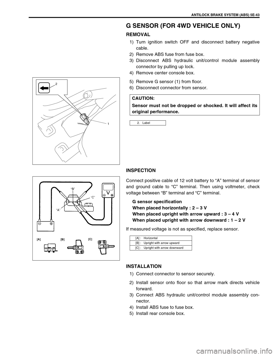
1) Turn ignition switch OFF and disconnect battery negative
cable.
2) Remove ABS fuse from fuse box.
3) Disconnect ABS hydraulic unit/control module assembly
connector by pulling up lock.
4) Remove center console box.
5) Remove G sensor (1) from floor.
6) Disconnect connector from sensor.
INSPECTION
Connect positive cable of 12 volt battery to “A” terminal of sensor
and ground cable to “C” terminal. Then using voltmeter, check
voltage between “B” terminal and “C” terminal.
G sensor specification
When placed horizontally : 2 – 3 V
When placed upright with arrow upward : 3 – 4 V
When placed upright with arrow downward : 1 – 2 V
If measured voltage is not as specified, replace sensor.
INSTALLATION
1) Connect connector to sensor securely.
2) Install sensor onto floor so that arrow mark directs vehicle
forward.
3) Connect ABS hydraulic unit/control module assembly con-
nector.
4) Install ABS fuse to fuse box.
5) Install rear console box.CAUTION:
Sensor must not be dropped or shocked. It will affect its
original performance.
2. Label1
2
[A] : Horizontal
[B] : Upright with arrow upward
[C] : Upright with arrow downward
Page 415 of 698
6-46 ENGINE GENERAL INFORMATION AND DIAGNOSIS
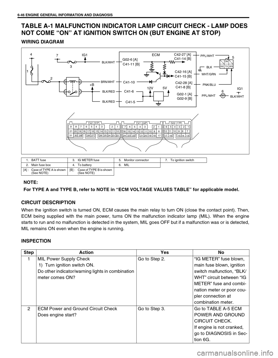
TABLE A-1 MALFUNCTION INDICATOR LAMP CIRCUIT CHECK - LAMP DOES
NOT COME “ON” AT IGNITION SWITCH ON (BUT ENGINE AT STOP)
WIRING DIAGRAM
CIRCUIT DESCRIPTION
When the ignition switch is turned ON, ECM causes the main relay to turn ON (close the contact point). Then,
ECM being supplied with the main power, turns ON the malfunction indicator lamp (MIL). When the engine
starts to run and no malfunction is detected in the system, MIL goes OFF but if a malfunction was or is detected,
MIL remains ON even when the engine is running.
INSPECTION
1. BATT fuse 3. IG METER fuse 5. Monitor connector 7. To ignition switch
2. Main fuse box 4. To battery 6. MIL
[A] : Case of TYPE A is shown
(See NOTE)[B] : Case of TYPE B is shown
(See NOTE)
1
12V5V
ECM
23
+BB
DA
C
BLK/WHT
BRN/WHT
BLK/RED
BLK/RED
C42 (31P) C41 (24P) G02 (17P)1 2 3 4 5 6 7 8 9
10 11 12 13 14 15 16 17 18 19 20 21
22 23 24 25 26 28 27 29 30 315 6
1 2 3 4 5 6 7
11 12
9 10 11 13 12 14 15 16
16 171 2
7 8
13 14 3 4
9 10
15 17 188
19 20 21 22 23 24
BLK
DN
TS
GNDMON
PPL/WHTC42-27 [A]
C42-16 [A]
PNK/BLUC42-28 [A]
7 4
G02-1 [A]IG1
5
6IG1
WHT/GRN
BLK/WHT
G02-6 [A]
C41-5 C41-6 C41-10 C41-11 [B]C41-14 [B]
C41-15 [B]
C41-8 [B]
G02-9 [B]
PPL/WHT
NOTE:
For TYPE A and TYPE B, refer to NOTE in “ECM VOLTAGE VALUES TABLE” for applicable model.
Step Action Yes No
1 MIL Power Supply Check
1) Turn ignition switch ON.
Do other indicator/warning lights in combination
meter comes ON?Go to Step 2.“IG METER” fuse blown,
main fuse blown, ignition
switch malfunction, “BLK/
WHT” circuit between “IG
METER” fuse and combi-
nation meter or poor cou-
pler connection at
combination meter.
2 ECM Power and Ground Circuit Check
Does engine start?Go to Step 3. Go to TABLE A-5 ECM
POWER AND GROUND
CIRCUIT CHECK.
If engine is not cranked,
go to DIAGNOSIS in Sec-
tion 6G.
Page 418 of 698
ENGINE GENERAL INFORMATION AND DIAGNOSIS 6-49
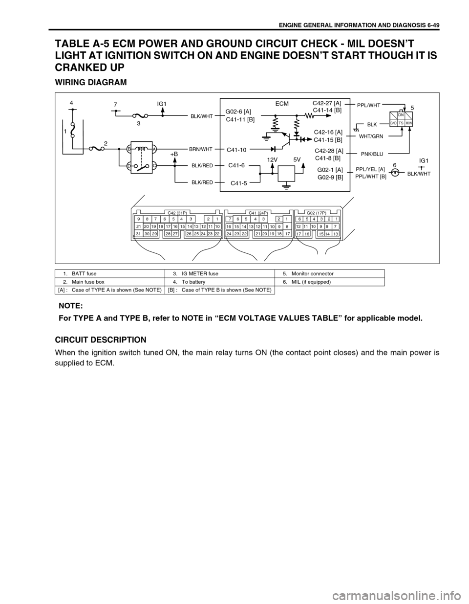
TABLE A-5 ECM POWER AND GROUND CIRCUIT CHECK - MIL DOESN’T
LIGHT AT IGNITION SWITCH ON AND ENGINE DOESN’T START THOUGH IT IS
CRANKED UP
WIRING DIAGRAM
CIRCUIT DESCRIPTION
When the ignition switch tuned ON, the main relay turns ON (the contact point closes) and the main power is
supplied to ECM.
1. BATT fuse 3. IG METER fuse 5. Monitor connector
2. Main fuse box 4. To battery 6. MIL (if equipped)
[A] : Case of TYPE A is shown (See NOTE) [B] : Case of TYPE B is shown (See NOTE)
1
12V5V
ECM
23
+BB
DA
C
BLK/WHT
BRN/WHT
BLK/RED
BLK/RED
C42 (31P) C41 (24P) G02 (17P)1 2 3 4 5 6 7 8 9
10 11 12 13 14 15 16 17 18 19 20 21
22 23 24 25 26 28 27 29 30 315 6
1 2 3 4 5 6 7
11 12
9 10 11 13 12 14 15 16
16 171 2
7 8
13 14 3 4
9 10
15 17 188
19 20 21 22 23 24
BLK
DN
TS
GNDMON
PPL/WHTC42-27 [A]
C42-16 [A]
PNK/BLUC42-28 [A]
7 4
G02-1 [A]IG1PPL/YEL [A]
5
6IG1
WHT/GRN
BLK/WHT
G02-6 [A]
C41-5 C41-6 C41-10 C41-11 [B]C41-14 [B]
C41-15 [B]
C41-8 [B]
G02-9 [B]PPL/WHT [B]
NOTE:
For TYPE A and TYPE B, refer to NOTE in “ECM VOLTAGE VALUES TABLE” for applicable model.
Page 570 of 698
ENGINE MECHANICAL (M13 ENGINE) 6A1-69
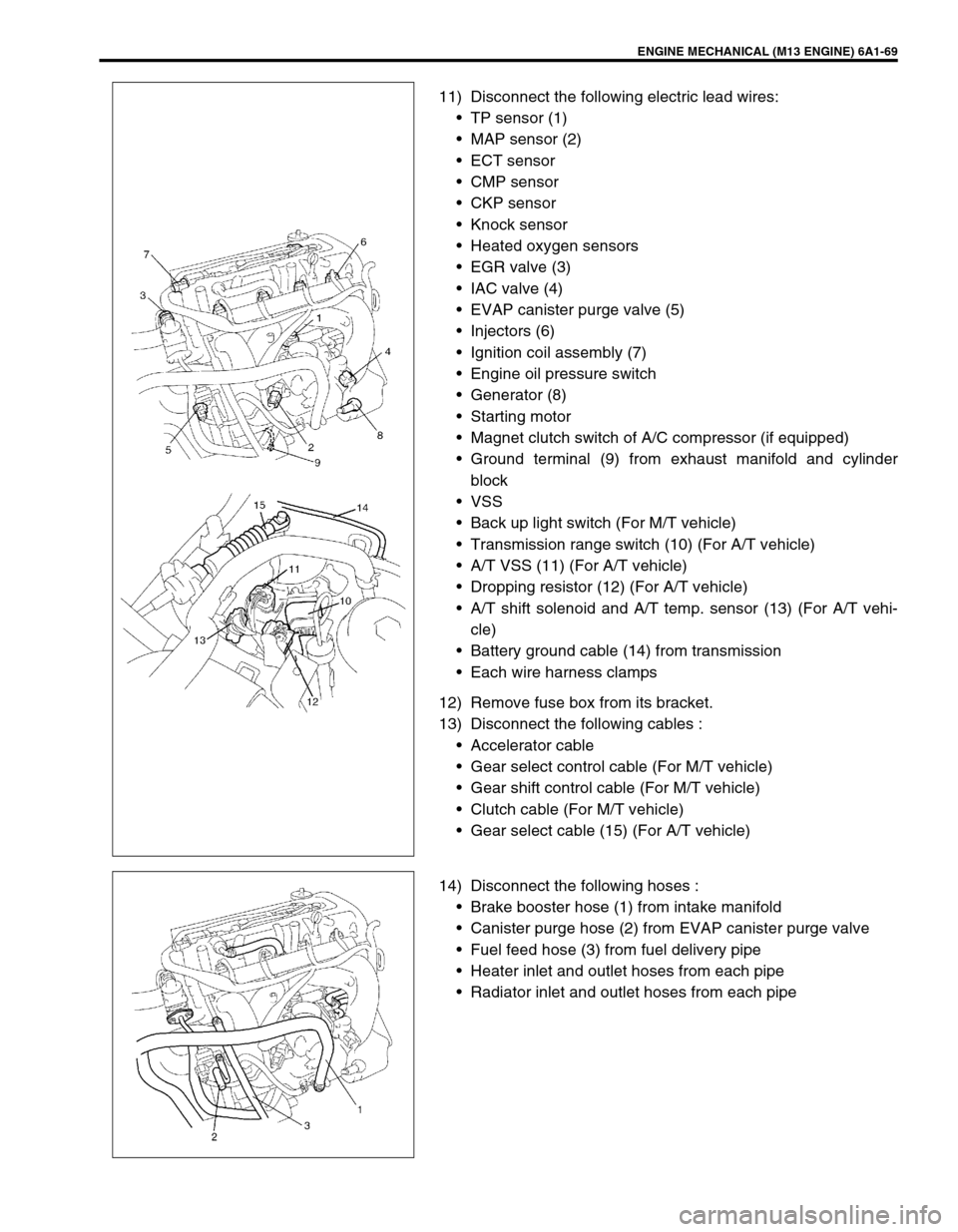
11) Disconnect the following electric lead wires:
TP sensor (1)
MAP sensor (2)
ECT sensor
CMP sensor
CKP sensor
Knock sensor
Heated oxygen sensors
EGR valve (3)
IAC valve (4)
EVAP canister purge valve (5)
Injectors (6)
Ignition coil assembly (7)
Engine oil pressure switch
Generator (8)
Starting motor
Magnet clutch switch of A/C compressor (if equipped)
Ground terminal (9) from exhaust manifold and cylinder
block
VSS
Back up light switch (For M/T vehicle)
Transmission range switch (10) (For A/T vehicle)
A/T VSS (11) (For A/T vehicle)
Dropping resistor (12) (For A/T vehicle)
A/T shift solenoid and A/T temp. sensor (13) (For A/T vehi-
cle)
Battery ground cable (14) from transmission
Each wire harness clamps
12) Remove fuse box from its bracket.
13) Disconnect the following cables :
Accelerator cable
Gear select control cable (For M/T vehicle)
Gear shift control cable (For M/T vehicle)
Clutch cable (For M/T vehicle)
Gear select cable (15) (For A/T vehicle)
14) Disconnect the following hoses :
Brake booster hose (1) from intake manifold
Canister purge hose (2) from EVAP canister purge valve
Fuel feed hose (3) from fuel delivery pipe
Heater inlet and outlet hoses from each pipe
Radiator inlet and outlet hoses from each pipe
Page 594 of 698
ENGINE COOLING 6B-5
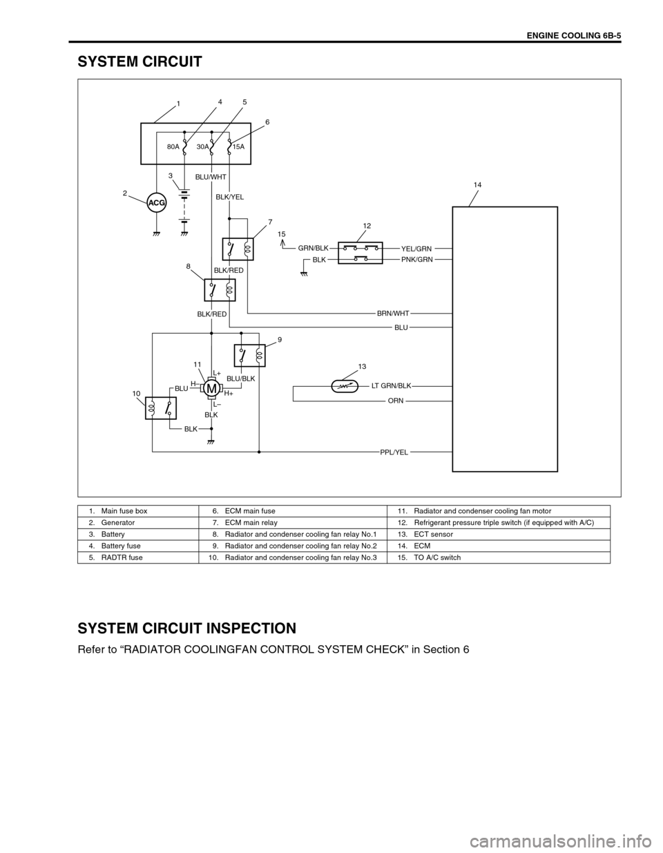
SYSTEM CIRCUIT
SYSTEM CIRCUIT INSPECTION
Refer to “RADIATOR COOLINGFAN CONTROL SYSTEM CHECK” in Section 6
1. Main fuse box 6. ECM main fuse 11. Radiator and condenser cooling fan motor
2. Generator 7. ECM main relay 12. Refrigerant pressure triple switch (if equipped with A/C)
3. Battery 8. Radiator and condenser cooling fan relay No.1 13. ECT sensor
4. Battery fuse 9. Radiator and condenser cooling fan relay No.2 14. ECM
5. RADTR fuse 10. Radiator and condenser cooling fan relay No.3 15. TO A/C switch
ACG
15A 30A
BLU/WHT
BLK/YEL
BLK
BLU
ORN
BLK
BLK
BLUH–
H+
L– L+
GRN/BLK
BLU/BLK
BRN/WHT
YEL/GRN
PNK/GRN
PPL/YEL
LT GRN/BLK
BLK/RED
BLK/RED 80A
145
6
2
3
7
8
9
11
10
13 15
12
14