ECM Location SUZUKI SWIFT 2000 1.G RG413 Service Workshop Manual
[x] Cancel search | Manufacturer: SUZUKI, Model Year: 2000, Model line: SWIFT, Model: SUZUKI SWIFT 2000 1.GPages: 698, PDF Size: 16.01 MB
Page 66 of 698
AIR CONDITIONING (OPTIONAL) 1B-1
6F1
6F2
6G
1B
7A
7A1
7B1
7C1
7D
7E
7F
8A
8B
8C
8D
8E
9
10
10A
10B
SECTION 1B
AIR CONDITIONING (OPTIONAL)
CONTENTS
GENERAL DESCRIPTION .............................. 1B-3
REFRIGERANT CIRCULATION .................. 1B-3
REFRIGERANT TYPE ................................. 1B-3
MAJOR COMPONENTS AND
LOCATION ................................................... 1B-4
DIAGNOSIS ..................................................... 1B-5
GENERAL DIAGNOSIS TABLE ................... 1B-5
ABNORMAL NOISE DIAGNOSIS ................ 1B-7
QUICKLY CHECKING OF REFRIGERANT
CHARGE ...................................................... 1B-9
PERFORMANCE DIAGNOSIS .................. 1B-10
PERFORMANCE DIAGNOSIS TABLE .. 1B-12
DETAIL DIAGNOSIS TABLE (AMBIENT
TEMPERATURE AT 30°C (86°F)) ......... 1B-13
COMPRESSOR DRIVE BELT ................... 1B-15ELECTRICAL DIAGNOSIS ........................... 1B-16
WIRING DIAGRAM .................................... 1B-16
A/C SYSTEM INSPECTION OF ECM AND
ITS CIRCUITS ........................................... 1B-17
REFRIGERANT RECOVERY, EVACUATING
AND CHARGING........................................... 1B-20
OPERATION PROCEDURE FOR
REFRIGERANT CHARGING ..................... 1B-20
RECOVERY ............................................... 1B-21
REPLENISHING COMPRESSOR OIL ...... 1B-21
EVACUATING............................................ 1B-22
EVACUATING PROCEDURE ................ 1B-22
CHECKING SYSTEM FOR PRESSURE
LEAKS.................................................... 1B-23
CHARGING................................................ 1B-24
CHARGING PROCEDURE .................... 1B-24 WARNING:
For vehicles equipped with Supplemental Restraint (Air Bag) System :
Service on and around the air bag system components or wiring must be performed only by an
authorized SUZUKI dealer. Refer to “Air Bag System Components and Wiring Location View” under
“General Description” in air bag system section in order to confirm whether you are performing ser-
vice on or near the air bag system components or wiring. Please observe all WARNINGS and “Ser-
vice Precautions” under “On-Vehicle Service” in air bag system section before performing service
on or around the air bag system components or wiring. Failure to follow WARNINGS could result in
unintentional activation of the system or could render the system inoperative. Either of these two
conditions may result in severe injury.
Technical service work must be started at least 90 seconds after the ignition switch is turned to the
“LOCK” position and the negative cable is disconnected from the battery. Otherwise, the system
may be activated by reserve energy in the Sensing and Diagnostic Module (SDM).
CAUTION:
The air conditioning system of this vehicle uses refrigerant HFC-134a (R-134a).
None of refrigerant, compressor oil and component parts is interchangeable between two types of
A/C : one using refrigerant HFC-134a (R-134a) and the other using refrigerant CFC-12 (R-12).
Be sure to check which refrigerant is used before any service work including inspection and mainte-
nance. For identification between these two types, refer to “REFRIGERANT TYPE” in this section.
When replenishing or changing refrigerant and compressor oil and when replacing parts, make sure
that the material or the part to be used is appropriate to the A/C installed in the vehicle being serviced.
Use of incorrect one will result in leakage of refrigerant, damage in parts or other faulty condition.
NOTE:
For basic servicing method of the air conditioning system that is not described in this section, refer to
“AIR CONDITIONING BASIC MANUAL (Part number : 99520-02130)”.
Page 143 of 698
3B1-2 ELECTRICAL POWER STEERING (P/S) SYSTEM
STEERING FORCE INSPECTION ........... 3B1-28
ON-VEHICLE SERVICE ............................... 3B1-29
P/S CONTROL MODULE ......................... 3B1-29
TORQUE SENSOR .................................. 3B1-29MOTOR AND CLUTCH ............................ 3B1-30
STEERING COLUMN ASSEMBLY .......... 3B1-31
SPECIAL TOOL ........................................... 3B1-31
GENERAL DESCRIPTION
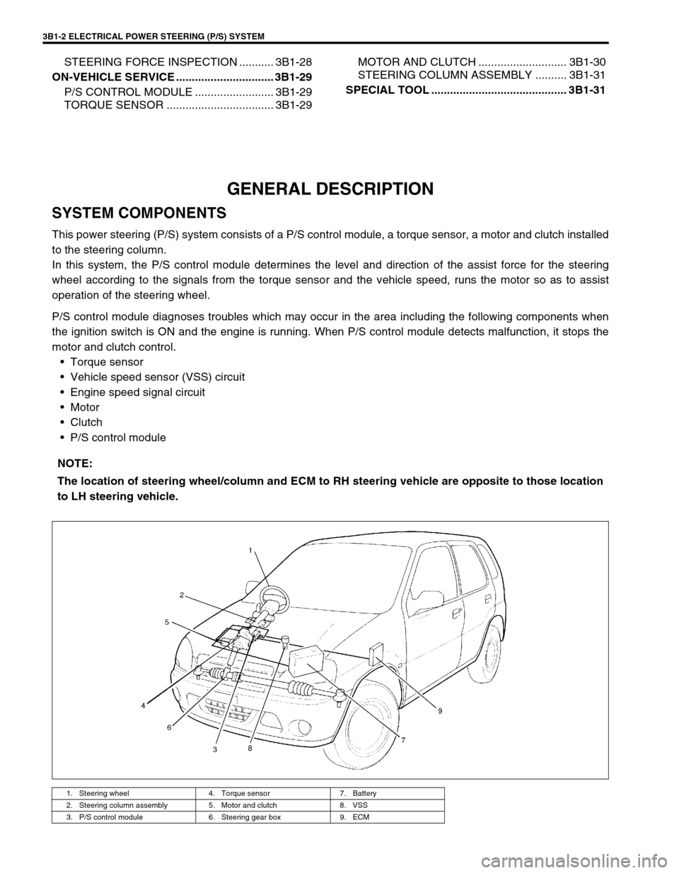
SYSTEM COMPONENTS
This power steering (P/S) system consists of a P/S control module, a torque sensor, a motor and clutch installed
to the steering column.
In this system, the P/S control module determines the level and direction of the assist force for the steering
wheel according to the signals from the torque sensor and the vehicle speed, runs the motor so as to assist
operation of the steering wheel.
P/S control module diagnoses troubles which may occur in the area including the following components when
the ignition switch is ON and the engine is running. When P/S control module detects malfunction, it stops the
motor and clutch control.
Torque sensor
Vehicle speed sensor (VSS) circuit
Engine speed signal circuit
Motor
Clutch
P/S control module
NOTE:
The location of steering wheel/column and ECM to RH steering vehicle are opposite to those location
to LH steering vehicle.
1. Steering wheel 4. Torque sensor 7. Battery
2. Steering column assembly 5. Motor and clutch 8. VSS
3. P/S control module 6. Steering gear box 9. ECM
Page 371 of 698
6-2 ENGINE GENERAL INFORMATION AND DIAGNOSIS
ENGINE DIAGNOSIS ......................................... 6-6
GENERAL DESCRIPTION ............................. 6-6
ON-BOARD DIAGNOSTIC SYSTEM
(VEHICLE WITH IMMOBILIZER INDICATOR
LAMP) ............................................................. 6-7
ON-BOARD DIAGNOSTIC SYSTEM
(VEHICLE WITHOUT IMMOBILIZER
INDICATOR LAMP) ...................................... 6-10
PRECAUTION IN DIAGNOSING
TROUBLE ..................................................... 6-11
ENGINE DIAGNOSTIC FLOW TABLE ......... 6-12
CUSTOMER PROBLEM INSPECTION
FORM (EXAMPLE) ................................... 6-14
MALFUNCTION INDICATOR LAMP (MIL)
CHECK...................................................... 6-15
DIAGNOSTIC TROUBLE CODE (DTC)
CHECK...................................................... 6-15
DIAGNOSTIC TROUBLE CODE (DTC)
CLEARANCE ............................................ 6-16
DIAGNOSTIC TROUBLE CODE (DTC)
TABLE ....................................................... 6-17
FAIL-SAFE TABLE.................................... 6-20
VISUAL INSPECTION .............................. 6-22
ENGINE BASIC INSPECTION.................. 6-23
ENGINE DIAGNOSIS TABLE ................... 6-26
SCAN TOOL DATA....................................... 6-31
INSPECTION OF ECM AND ITS
CIRCUITS ..................................................... 6-36
ECM VOLTAGE VALUES TABLE............. 6-37
TERMINAL RESISTANCE TABLE............ 6-43
COMPONENT LOCATION ........................... 6-45
TABLE A-1 MALFUNCTION INDICATOR
LAMP CIRCUIT CHECK - LAMP DOES NOT
COME “ON” AT IGNITION SWITCH ON
(BUT ENGINE AT STOP) ............................. 6-46
TABLE A-2 MALFUNCTION INDICATOR
LAMP CIRCUIT CHECK - LAMP REMAINS
“ON” AFTER ENGINE STARTS ................... 6-47
TABLE A-3 MIL CHECK - MIL FLASHES
AT IGNITION SWITCH ON (VEHICLE
WITHOUT IMMOBILIZER INDICATOR
LAMP) ........................................................... 6-48
TABLE A-4 MIL CHECK - MIL DOES NOT
FLASH OR JUST REMAINS ON EVEN
WITH GROUNDING DIAGNOSIS SWITCH
TERMINAL (VEHICLE WITHOUT
IMMOBILIZER INDICATOR LAMP) .............. 6-48
TABLE A-5 ECM POWER AND GROUND
CIRCUIT CHECK - MIL DOESN’T LIGHT
AT IGNITION SWITCH ON AND ENGINE
DOESN’T START THOUGH IT IS
CRANKED UP .............................................. 6-49
DTC P0105 (DTC NO.11) MANIFOLD
ABSOLUTE PRESSURE (MAP) CIRCUIT
MALFUNCTION ............................................ 6-52
DTC P0110 (DTC NO.18) INTAKE AIR
TEMP. (IAT) CIRCUIT MALFUNCTION ....... 6-55
DTC P0115 (DTC NO.19) ENGINE
COOLANT TEMPERATURE (ECT) CIRCUIT
MALFUNCTION ............................................ 6-57DTC P0120 (DTC NO.13) THROTTLE
POSITION CIRCUIT MALFUNCTION ........... 6-60
DTC P0121 THROTTLE POSITION CIRCUIT
RANGE/PERFORMANCE PROBLEM .......... 6-63
DTC P0130 (DTC NO.14) HEATED OXYGEN
SENSOR (HO2S) CIRCUIT MALFUNCTION
(SENSOR-1) .................................................. 6-66
DTC P0133 HEATED OXYGEN SENSOR
(HO2S) CIRCUIT SLOW RESPONSE
(SENSOR-1) .................................................. 6-68
DTC P0134 HEATED OXYGEN SENSOR
(HO2S) CIRCUIT NO ACTIVITY DETECTED
(SENSOR-1) .................................................. 6-69
DTC P0135 (DTC NO.14) HEATED OXYGEN
SENSOR (HO2S) HEATER CIRCUIT
MALFUNCTION (SENSOR-1) ....................... 6-70
DTC P0136 HEATED OXYGEN SENSOR
(HO2S) CIRCUIT MALFUNCTION
(SENSOR-2) .................................................. 6-72
DTC P0141 HEATED OXYGEN SENSOR
(HO2S) HEATER CIRCUIT MALFUNCTION
(SENSOR-2) .................................................. 6-74
DTC P0171 FUEL SYSTEM TOO LEAN ....... 6-76
DTC P0172 FUEL SYSTEM TOO RICH ....... 6-76
DTC P0300 RANDOM MISFIRE DETECTED
(MISFIRE DETECTED AT 2 OR MORE
CYLINDERS) ................................................. 6-81
DTC P0301 CYLINDER 1 MISFIRE
DETECTED ................................................... 6-81
DTC P0302 CYLINDER 2 MISFIRE
DETECTED ................................................... 6-81
DTC P0303 CYLINDER 3 MISFIRE
DETECTED ................................................... 6-81
DTC P0304 CYLINDER 4 MISFIRE
DETECTED ................................................... 6-81
DTC P0325 (DTC NO.17) KNOCK SENSOR
CIRCUIT MALFUNCTION ............................. 6-86
DTC P0335 (DTC NO.23) CRANKSHAFT
POSITION (CKP) SENSOR CIRCUIT
MALFUNCTION ............................................. 6-88
DTC P0340 (DTC NO.15) CAMSHAFT
POSITION (CMP) SENSOR CIRCUIT
MALFUNCTION ............................................. 6-91
DTC P0400 EXHAUST GAS
RECIRCULATION FLOW MALFUNCTION ... 6-94
DTC P0420 CATALYST SYSTEM
EFFICIENCY BELOW THRESHOLD ............ 6-97
DTC P0443 PURGE CONTROL VALVE
CIRCUIT MALFUNCTION ........................... 6-100
DTC P0480 RADIATOR COOLING FAN
CONTROL SYSTEM MALFUNCTION ........ 6-101
DTC P0500 (DTC NO.16) VEHICLE SPEED
SENSOR (VSS) MALFUNCTION ................ 6-103
DTC P0505 (DTC NO.26) IDLE CONTROL
SYSTEM MALFUNCTION ........................... 6-105
DTC P1450 BAROMETRIC PRESSURE
SENSOR LOW/HIGH INPUT....................... 6-108
DTC P1451 BAROMETRIC PRESSURE
SENSOR PERFORMANCE PROBLEM ...... 6-108
Page 397 of 698
6-28 ENGINE GENERAL INFORMATION AND DIAGNOSIS
Poor gasoline mile-
age Leaks or loose connection of high-tension
cordHigh-tension cords in Section 6F1.
Faulty spark plug (improper gap, heavy
deposits and burned electrodes, etc.)Spark plugs in Section 6F1.
Malfunctioning EGR valve (if equipped) EGR system in Section 6E1.
High idle speed Refer to item “Improper engine idle
speed” previously outlined.
Poor performance of TP sensor, ECT sensor
or MAP sensorTP sensor, ECT sensor or MAP sensor
in Section 6E1.
Faulty EGR valve (if equipped) EGR system in Section 6E1.
Faulty fuel injector(s) Diagnostic Flow Table B-1.
Faulty ECM
Poor valve seating Valves inspection in Section 6A1.
Dragging brakes Trouble diagnosis in Section 5.
Slipping clutch Trouble diagnosis in Section 7C.
Thermostat out of order Thermostat in Section 6B.
Improper tire pressure Refer to Section 3F.
Low Compression Previously outlined
Excessive engine
oil consumption Blown cylinder head gasket Cylinder head in Section 6A1.
Leaky camshaft oil seals Camshaft in Section 6A1.
Sticky piston ring Piston cleaning in Section 6A1.
Worn piston and cylinder Pistons and cylinders inspection in Sec-
tion 6A1.
Worn piston ring groove and ring Pistons inspection in Section 6A1.
Improper location of piston ring gap Pistons assembly in Section 6A1.
Worn or damaged valve stem seal Valves removal and installation in Sec-
tion 6A1.
Worn valve stem Valves inspection in Section 6A1.
Engine hesitates
(Momentary lack of
response as accel-
erator is depressed.
Can occur at all
vehicle speeds.
Usually most severe
when first trying to
make vehicle move,
as from a stop sign.)Spark plug faulty or plug gap out of adjust-
mentSpark plugs in Section 6F1.
Leaky high-tension cord High-tension cords in Section 6F1.
Fuel pressure out of specification Diagnostic Flow Table B-3.
Malfunctioning EGR valve (if equipped) EGR system in section 6E1.
Poor performance of TP sensor, ECT sensor
or MAP sensorTP sensor, ECT sensor or MAP sensor
in Section 6E1.
Faulty fuel injector Diagnostic Flow Table B-1.
Faulty ECM
Engine overheating Refer to “Overheating” section.
Low compression Previously outlined.
Surge
(Engine power vari-
ation under steady
throttle or cruise.
Feels like vehicle
speeds up and
down with no
change in accelera-
tor pedal.)Leaky or loosely connected high-tension cord High-tension cords in Section 6F1.
Faulty spark plug (excess carbon deposits,
improper gap, and burned electrodes, etc.)Spark plugs in Section 6F1.
Variable fuel pressure Diagnostic Flow Table B-3.
Kinky or damaged fuel hose and lines
Faulty fuel pump (clogged fuel filter)
Malfunctioning EGR valve EGR system in Section 6E1.
Poor performance of MAP sensor MAP sensor in Section 6E1.
Faulty fuel injector Diagnostic Flow Table B-1.
Faulty ECM Condition Possible Cause Correction
Page 414 of 698
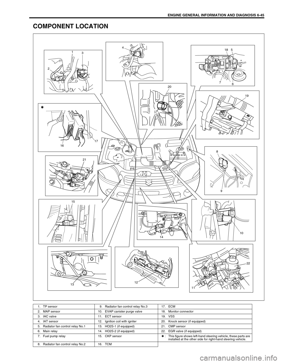
ENGINE GENERAL INFORMATION AND DIAGNOSIS 6-45
COMPONENT LOCATION
1. TP sensor 9. Radiator fan control relay No.3 17. ECM
2. MAP sensor 10. EVAP canister purge valve 18. Monitor connector
3. IAC valve 11. ECT sensor 19. VSS
4. IAT sensor 12. Ignition coil with igniter 20. Knock sensor (if equipped)
5. Radiator fan control relay No.1 13. HO2S-1 (if equipped) 21. CMP sensor
6. Main relay 14. HO2S-2 (if equipped) 22. EGR valve (if equipped)
7. Fuel pump relay 15. CKP sensor✱ : This figure shows left-hand steering vehicle, these parts are
installed at the other side for right-hand steering vehicle.
8. Radiator fan control relay No.2 16. TCM
1
3
24
518
6 7
20
19
8
9 1617
21
15
131214
10
22
11
Page 622 of 698
ENGINE AND EMISSION CONTROL SYSTEM 6E1-1
6F1
6F2
6G
6H
6E1
7A
7A1
7B1
7C1
7D
7E
7F
8A
8B
8C
8D
8E
9
10
10A
10B
SECTION 6E1
ENGINE AND EMISSION CONTROL SYSTEM
CONTENTS
GENERAL DESCRIPTION ............................ 6E1-2
AIR INTAKE SYSTEM ............................... 6E1-5
FUEL DELIVERY SYSTEM ....................... 6E1-6
FUEL PUMP ........................................... 6E1-6
ELECTRONIC CONTROL SYSTEM .......... 6E1-7
ENGINE & EMISSION CONTROL
INPUT/OUTPUT TABLE ........................ 6E1-8
ECM INPUT/OUTPUT CIRCUIT
DIAGRAM............................................... 6E1-9
ECM TERMINAL ARRANGEMENT
TABLE .................................................. 6E1-13
ON-VEHICLE SERVICE .............................. 6E1-15
ACCELERATOR CABLE
ADJUSTMENT ..................................... 6E1-15
IDLE SPEED/IDLE AIR CONTROL
(IAC) DUTY INSPECTION ................... 6E1-15
IDLE MIXTURE INSPECTION /
ADJUSTMENT (VEHICLE WITHOUT
HEATED OXYGEN SENSOR) ............. 6E1-17
AIR INTAKE SYSTEM ............................. 6E1-18
THROTTLE BODY ............................... 6E1-18IDLE AIR CONTROL VALVE (IAC
VALVE) ................................................ 6E1-20
FUEL DELIVERY SYSTEM ..................... 6E1-21
FUEL PRESSURE INSPECTION ........ 6E1-21
FUEL PUMP WITH PRESSURE
REGULATOR ....................................... 6E1-22
FUEL INJECTOR ................................. 6E1-23
ELECTRONIC CONTROL SYSTEM ....... 6E1-27
ENGINE CONTROL MODULE
(ECM) ................................................... 6E1-27
MANIFOLD ABSOLUTE PRESSURE
SENSOR (MAP SENSOR)................... 6E1-27
THROTTLE POSITION SENSOR (TP
SENSOR) ............................................. 6E1-28
INTAKE AIR TEMPERATURE
SENSOR (IAT SENSOR) ..................... 6E1-29
ENGINE COOLANT TEMPERATURE
SENSOR (ECT SENSOR) ................... 6E1-30
HEATED OXYGEN SENSOR (HO2S-1
AND HO2S-2) ...................................... 6E1-31
CAMSHAFT POSITION SENSOR ....... 6E1-32 WARNING:
For vehicles equipped with Supplemental Restraint (Air Bag) System :
Service on and around the air bag system components or wiring must be performed only by an
authorized SUZUKI dealer. Refer to “Air Bag System Components and Wiring Location View” under
“General Description” in air bag system section in order to confirm whether you are performing ser-
vice on or near the air bag system components or wiring. Please observe all WARNINGS and “Ser-
vice Precautions” under “On-Vehicle Service” in air bag system section before performing service
on or around the air bag system components or wiring. Failure to follow WARNINGS could result in
unintentional activation of the system or could render the system inoperative. Either of these two
conditions may result in severe injury.
Technical service work must be started at least 90 seconds after the ignition switch is turned to the
“LOCK” position and the negative cable is disconnected from the battery. Otherwise, the system
may be activated by reserve energy in the Sensing and Diagnostic Module (SDM).
NOTE:
Whether the following system (parts) are used in the particular vehicle or not depends on vehicle
specifications. Be sure to bear this in mind when performing service work.
EGR valve
Heated oxygen sensor(s) or CO adjusting resistor
Three way catalytic converter
Immobilizer indicator lamp
Knock sensor