dead battery SUZUKI SWIFT 2000 1.G RG413 Service Workshop Manual
[x] Cancel search | Manufacturer: SUZUKI, Model Year: 2000, Model line: SWIFT, Model: SUZUKI SWIFT 2000 1.GPages: 698, PDF Size: 16.01 MB
Page 25 of 698

0A-22 GENERAL INFORMATION
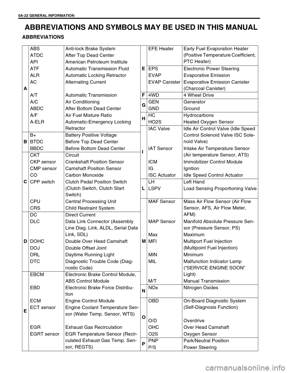
ABBREVIATIONS AND SYMBOLS MAY BE USED IN THIS MANUAL
ABBREVIATIONS
AABS Anti-lock Brake System
EEFE Heater Early Fuel Evaporation Heater
(Positive Temperature Coefficient,
PTC Heater) ATDC After Top Dead Center
API American Petroleum Institute
ATF Automatic Transmission Fluid EPS Electronic Power Steering
ALR Automatic Locking Retractor EVAP Evaporative Emission
AC Alternating Current EVAP Canister Evaporative Emission Canister
(Charcoal Canister)
A/T Automatic TransmissionF
4WD 4 Wheel Drive
A/C Air Conditioning
GGEN Generator
ABDC After Bottom Dead Center GND Ground
A/F Air Fuel Mixture Ratio
HHC Hydrocarbons
A-ELR Automatic-Emergency Locking
RetractorHO2S Heated Oxygen Sensor
IIAC Valve Idle Air Control Valve (Idle Speed
Control Solenoid Valve ISC Sole-
noid Valve)
BB+ Battery Positive Voltage
BTDC Before Top Dead Center
BBDC Before Bottom Dead Center IAT Sensor Intake Air Temperature Sensor
(Air temperature Sensor, ATS)
CCKT Circuit
CKP sensor Crankshaft Position Sensor ICM Immobilizer Control Module
CMP sensor Camshaft Position Sensor IG Ignition
CO Carbon Monoxide ISC Actuator Idle Speed Control Actuator
CPP switch Clutch Pedal Position Switch
(Clutch Switch, Clutch Start
Switch)LLH Left Hand
LSPV Load Sensing Proportioning Valve
CPU Central Processing Unit
MMAF Sensor Mass Air Flow Sensor (Air Flow
Sensor, AFS, Air Flow Meter,
AFM) CRS Child Restraint System
DDC Direct Current
DLC Data Link Connector (Assembly
Line Diag. Link, ALDL, Serial Data
Link, SDL)MAP Sensor Manifold Absolute Pressure Sen-
sor (Pressure Sensor, PS)
Max Maximum
DOHC Double Over Head Camshaft MFI Multiport Fuel Injection
(Multipoint Fuel Injection)
DOJ Double Offset Joint
DRL Daytime Running Light MIN Minimum
DTC Diagnostic Trouble Code (Diag-
nostic Code)MIL Malfunction Indicator Lamp
(“SERVICE ENGINE SOON”
Light)
EEBCM Electronic Brake Control Module,
ABS Control Module M/T Manual Transmission
EBD Electronic Brake Force Distribu-
tionNNOx Nitrogen Oxides
ECM Engine Control Module
OOBD On-Board Diagnostic System
(Self-Diagnosis Function)
ECT sensor Engine Coolant Temperature Sen-
sor (Water Temp. Sensor, WTS)
O/D Overdrive
EGR Exhaust Gas Recirculation OHC Over Head Camshaft
EGRT sensor EGR Temperature Sensor (Recir-
culated Exhaust Gas Temp. Sen-
sor, REGTS)O2S Oxygen Sensor
PPNP Park/Neutral Position
P/S Power Steering
Page 689 of 698

CHARGING SYSTEM 6H-9
ON-VEHICLE SERVICE
BATTERY
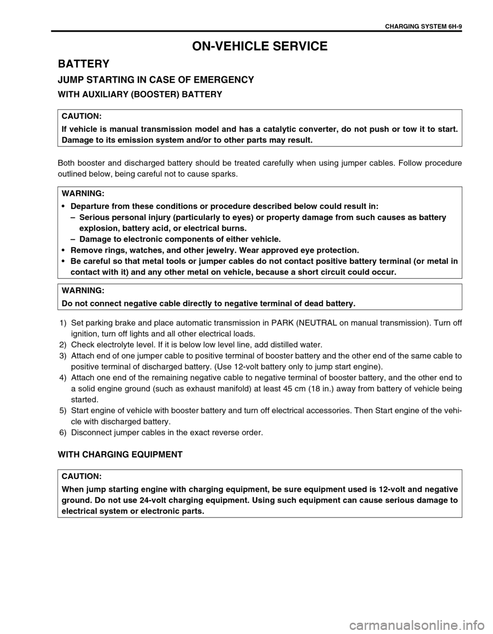
JUMP STARTING IN CASE OF EMERGENCY
WITH AUXILIARY (BOOSTER) BATTERY
Both booster and discharged battery should be treated carefully when using jumper cables. Follow procedure
outlined below, being careful not to cause sparks.
1) Set parking brake and place automatic transmission in PARK (NEUTRAL on manual transmission). Turn off
ignition, turn off lights and all other electrical loads.
2) Check electrolyte level. If it is below low level line, add distilled water.
3) Attach end of one jumper cable to positive terminal of booster battery and the other end of the same cable to
positive terminal of discharged battery. (Use 12-volt battery only to jump start engine).
4) Attach one end of the remaining negative cable to negative terminal of booster battery, and the other end to
a solid engine ground (such as exhaust manifold) at least 45 cm (18 in.) away from battery of vehicle being
started.
5) Start engine of vehicle with booster battery and turn off electrical accessories. Then Start engine of the vehi-
cle with discharged battery.
6) Disconnect jumper cables in the exact reverse order.
WITH CHARGING EQUIPMENT
CAUTION:
If vehicle is manual transmission model and has a catalytic converter, do not push or tow it to start.
Damage to its emission system and/or to other parts may result.
WARNING:
Departure from these conditions or procedure described below could result in:
–Serious personal injury (particularly to eyes) or property damage from such causes as battery
explosion, battery acid, or electrical burns.
–Damage to electronic components of either vehicle.
Remove rings, watches, and other jewelry. Wear approved eye protection.
Be careful so that metal tools or jumper cables do not contact positive battery terminal (or metal in
contact with it) and any other metal on vehicle, because a short circuit could occur.
WARNING:
Do not connect negative cable directly to negative terminal of dead battery.
CAUTION:
When jump starting engine with charging equipment, be sure equipment used is 12-volt and negative
ground. Do not use 24-volt charging equipment. Using such equipment can cause serious damage to
electrical system or electronic parts.