fuel consumption SUZUKI SWIFT 2000 1.G RG413 Service Workshop Manual
[x] Cancel search | Manufacturer: SUZUKI, Model Year: 2000, Model line: SWIFT, Model: SUZUKI SWIFT 2000 1.GPages: 698, PDF Size: 16.01 MB
Page 251 of 698

3F-6 WHEELS AND TIRES
INFLATION OF TIRES
The pressure recommended for any model is carefully calculated to give a satisfactory ride, stability, steering,
tread wear, tire life and resistance to bruises.
Tire pressure, with tires cold, (after vehicle has set for 3 hours or more, or driven less than one mile) should be
checked monthly or before any extended trip. Set to the specifications on the “Tire Placard” located on the left
door (right door for right-hand side steering vehicle) lock pillar.
It is normal for tire pressure to increase when the tires become hot during driving.
Do not bleed or reduce tire pressure after driving. Bleeding reduces the “Cold Inflation Pressure”.
Higher than recommended pressure can cause :
Hard ride
Tire bruising or carcass damage
Rapid tread wear at center of tire
Unequal pressure on same axle can cause :
Uneven braking
Steering lead
Reduced handling
Swerve on acceleration
Lower than recommended pressure can cause :
Tire squeal on turns
Hard Steering
Rapid and uneven wear on the edges of the tread
Tire rim bruises and rupture
Tire cord breakage
High tire temperature
Reduced handling
High fuel consumption
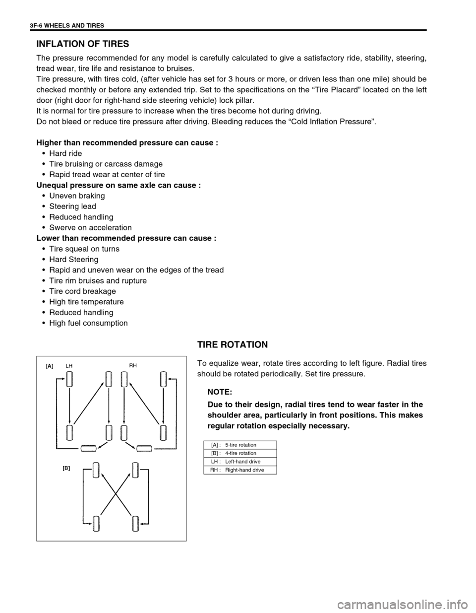
TIRE ROTATION
To equalize wear, rotate tires according to left figure. Radial tires
should be rotated periodically. Set tire pressure.
NOTE:
Due to their design, radial tires tend to wear faster in the
shoulder area, particularly in front positions. This makes
regular rotation especially necessary.
[A] : 5-tire rotation
[B] : 4-tire rotation
LH : Left-hand drive
RH : Right-hand drive
Page 389 of 698

6-20 ENGINE GENERAL INFORMATION AND DIAGNOSIS
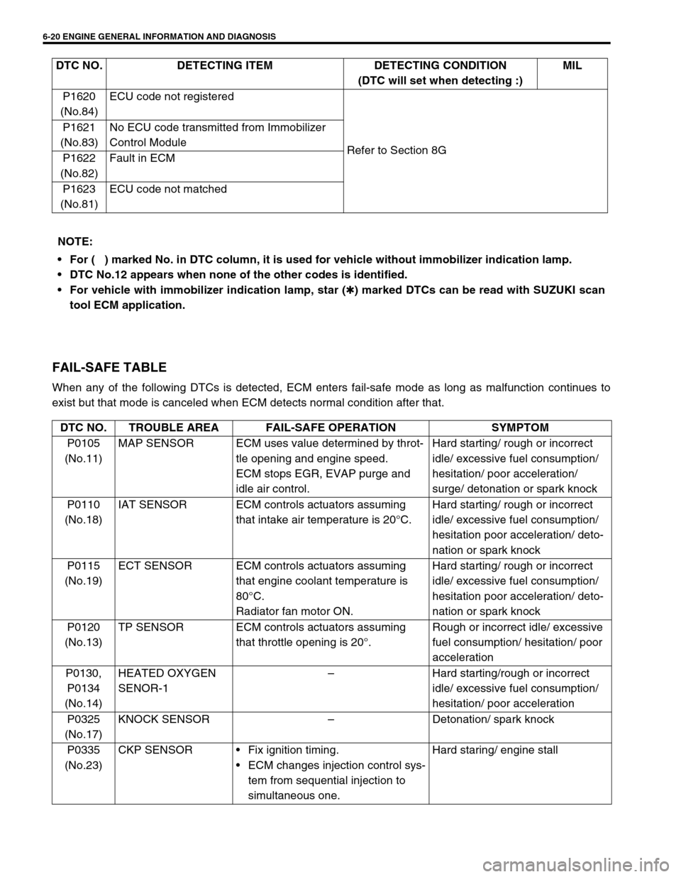
FAIL-SAFE TABLE
When any of the following DTCs is detected, ECM enters fail-safe mode as long as malfunction continues to
exist but that mode is canceled when ECM detects normal condition after that.P1620
(No.84)ECU code not registered
Refer to Section 8G P1621
(No.83)No ECU code transmitted from Immobilizer
Control Module
P1622
(No.82)Fault in ECM
P1623
(No.81)ECU code not matched DTC NO. DETECTING ITEM DETECTING CONDITION
(DTC will set when detecting :)MIL
NOTE:
For (
) marked No. in DTC column, it is used for vehicle without immobilizer indication lamp.
DTC No.12 appears when none of the other codes is identified.
For vehicle with immobilizer indication lamp, star (
✱) marked DTCs can be read with SUZUKI scan
tool ECM application.
DTC NO. TROUBLE AREA FAIL-SAFE OPERATION SYMPTOM
P0105
(No.11)MAP SENSOR ECM uses value determined by throt-
tle opening and engine speed.
ECM stops EGR, EVAP purge and
idle air control.Hard starting/ rough or incorrect
idle/ excessive fuel consumption/
hesitation/ poor acceleration/
surge/ detonation or spark knock
P0110
(No.18)IAT SENSOR ECM controls actuators assuming
that intake air temperature is 20°C.Hard starting/ rough or incorrect
idle/ excessive fuel consumption/
hesitation poor acceleration/ deto-
nation or spark knock
P0115
(No.19)ECT SENSOR ECM controls actuators assuming
that engine coolant temperature is
80°C.
Radiator fan motor ON.Hard starting/ rough or incorrect
idle/ excessive fuel consumption/
hesitation poor acceleration/ deto-
nation or spark knock
P0120
(No.13)TP SENSOR ECM controls actuators assuming
that throttle opening is 20°.Rough or incorrect idle/ excessive
fuel consumption/ hesitation/ poor
acceleration
P0130,
P0134
(No.14)HEATED OXYGEN
SENOR-1–Hard starting/rough or incorrect
idle/ excessive fuel consumption/
hesitation/ poor acceleration
P0325
(No.17)KNOCK SENSOR–Detonation/ spark knock
P0335
(No.23)CKP SENSORFix ignition timing.
ECM changes injection control sys-
tem from sequential injection to
simultaneous one.Hard staring/ engine stall
Page 390 of 698

ENGINE GENERAL INFORMATION AND DIAGNOSIS 6-21
P0340
(No.15)CMP SENSOR ECM changes injection control sys-
tem from sequential injection to simul-
taneous one.Hard starting
P0400 EGR VALVE–Hard starting/rough or incorrect
idle/ excessive fuel consumption/
hesitation/ poor acceleration/
surge/ detonation or spark knock/
engine stall
P0420 CATALYST––
P0443 PURGE CONTROL
VALVE–Rough or incorrect idle/ surge/
hard starting/ engine stall
P0480 RADIATOR FAN
CONTROL SYSTEM–Engine overheating
P0500
(No.16)VEHICLE SPEED
SENSORECM stops idle air control. Rough or incorrect idle
P0505 IDLE CONTROL
SYSTEM–Engine stall/ rough or incorrect idle
P0601
(No.71)ECM INTERNAL–Hard starting/ rough or incorrect
idle/ excessive fuel consumption/
detonation or spark knock/ hesita-
tion poor acceleration/
P1450
(No.29)BAROMETRIC
PRESSURE SEN-
SORECM controls actuators assuming
that barometric pressure is
100 kPa (760 mmHg).Hard starting/ rough or incorrect
idle DTC NO. TROUBLE AREA FAIL-SAFE OPERATION SYMPTOM
Page 397 of 698

6-28 ENGINE GENERAL INFORMATION AND DIAGNOSIS
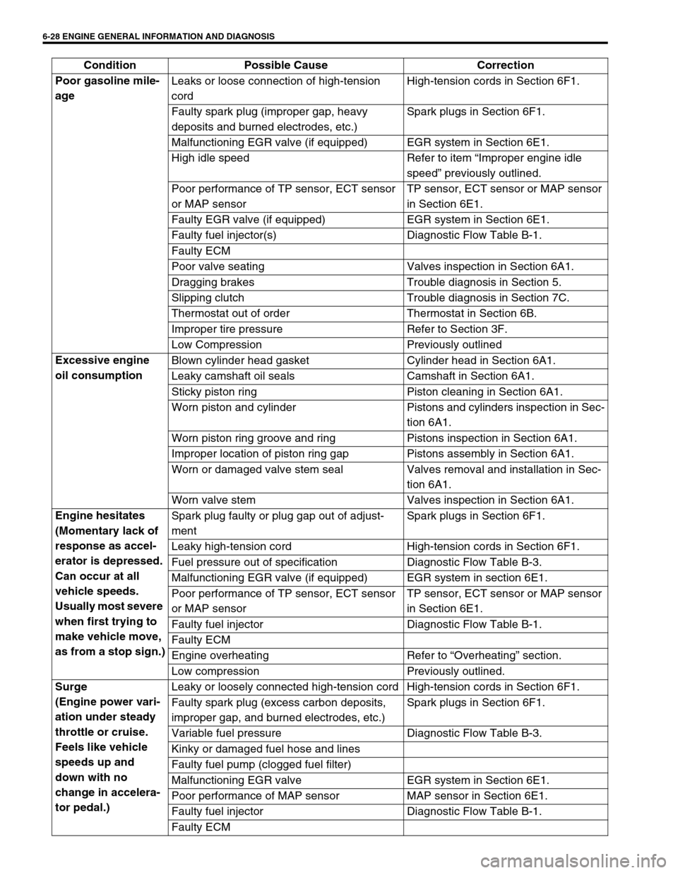
Poor gasoline mile-
age Leaks or loose connection of high-tension
cordHigh-tension cords in Section 6F1.
Faulty spark plug (improper gap, heavy
deposits and burned electrodes, etc.)Spark plugs in Section 6F1.
Malfunctioning EGR valve (if equipped) EGR system in Section 6E1.
High idle speed Refer to item “Improper engine idle
speed” previously outlined.
Poor performance of TP sensor, ECT sensor
or MAP sensorTP sensor, ECT sensor or MAP sensor
in Section 6E1.
Faulty EGR valve (if equipped) EGR system in Section 6E1.
Faulty fuel injector(s) Diagnostic Flow Table B-1.
Faulty ECM
Poor valve seating Valves inspection in Section 6A1.
Dragging brakes Trouble diagnosis in Section 5.
Slipping clutch Trouble diagnosis in Section 7C.
Thermostat out of order Thermostat in Section 6B.
Improper tire pressure Refer to Section 3F.
Low Compression Previously outlined
Excessive engine
oil consumption Blown cylinder head gasket Cylinder head in Section 6A1.
Leaky camshaft oil seals Camshaft in Section 6A1.
Sticky piston ring Piston cleaning in Section 6A1.
Worn piston and cylinder Pistons and cylinders inspection in Sec-
tion 6A1.
Worn piston ring groove and ring Pistons inspection in Section 6A1.
Improper location of piston ring gap Pistons assembly in Section 6A1.
Worn or damaged valve stem seal Valves removal and installation in Sec-
tion 6A1.
Worn valve stem Valves inspection in Section 6A1.
Engine hesitates
(Momentary lack of
response as accel-
erator is depressed.
Can occur at all
vehicle speeds.
Usually most severe
when first trying to
make vehicle move,
as from a stop sign.)Spark plug faulty or plug gap out of adjust-
mentSpark plugs in Section 6F1.
Leaky high-tension cord High-tension cords in Section 6F1.
Fuel pressure out of specification Diagnostic Flow Table B-3.
Malfunctioning EGR valve (if equipped) EGR system in section 6E1.
Poor performance of TP sensor, ECT sensor
or MAP sensorTP sensor, ECT sensor or MAP sensor
in Section 6E1.
Faulty fuel injector Diagnostic Flow Table B-1.
Faulty ECM
Engine overheating Refer to “Overheating” section.
Low compression Previously outlined.
Surge
(Engine power vari-
ation under steady
throttle or cruise.
Feels like vehicle
speeds up and
down with no
change in accelera-
tor pedal.)Leaky or loosely connected high-tension cord High-tension cords in Section 6F1.
Faulty spark plug (excess carbon deposits,
improper gap, and burned electrodes, etc.)Spark plugs in Section 6F1.
Variable fuel pressure Diagnostic Flow Table B-3.
Kinky or damaged fuel hose and lines
Faulty fuel pump (clogged fuel filter)
Malfunctioning EGR valve EGR system in Section 6E1.
Poor performance of MAP sensor MAP sensor in Section 6E1.
Faulty fuel injector Diagnostic Flow Table B-1.
Faulty ECM Condition Possible Cause Correction