oil type SUZUKI SWIFT 2000 1.G RG413 Service Workshop Manual
[x] Cancel search | Manufacturer: SUZUKI, Model Year: 2000, Model line: SWIFT, Model: SUZUKI SWIFT 2000 1.GPages: 698, PDF Size: 16.01 MB
Page 11 of 698
0A-8 GENERAL INFORMATION
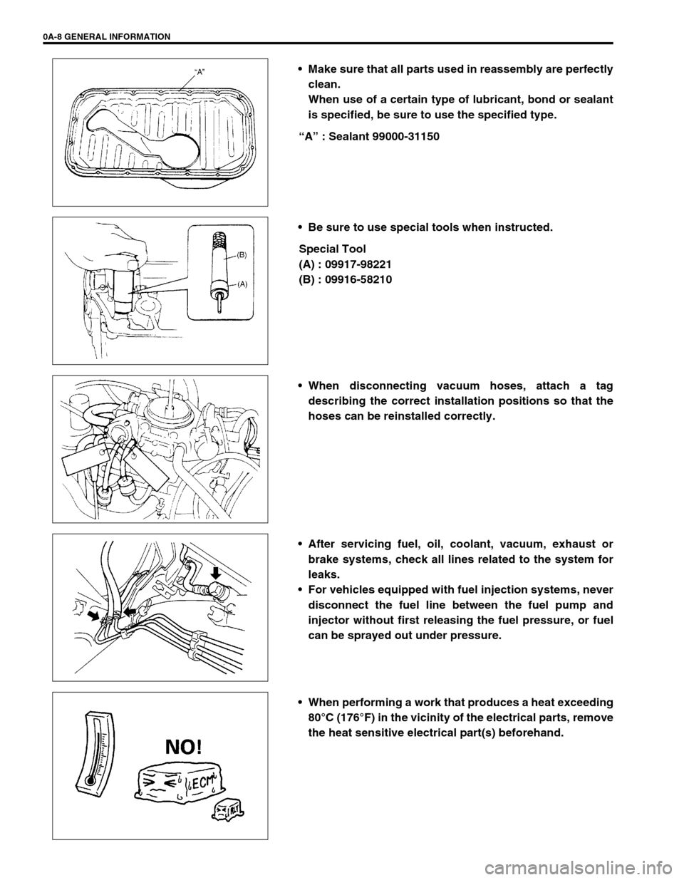
Make sure that all parts used in reassembly are perfectly
clean.
When use of a certain type of lubricant, bond or sealant
is specified, be sure to use the specified type.
“A” : Sealant 99000-31150
Be sure to use special tools when instructed.
Special Tool
(A) : 09917-98221
(B) : 09916-58210
When disconnecting vacuum hoses, attach a tag
describing the correct installation positions so that the
hoses can be reinstalled correctly.
After servicing fuel, oil, coolant, vacuum, exhaust or
brake systems, check all lines related to the system for
leaks.
For vehicles equipped with fuel injection systems, never
disconnect the fuel line between the fuel pump and
injector without first releasing the fuel pressure, or fuel
can be sprayed out under pressure.
When performing a work that produces a heat exceeding
80°C (176°F) in the vicinity of the electrical parts, remove
the heat sensitive electrical part(s) beforehand.
Page 66 of 698
AIR CONDITIONING (OPTIONAL) 1B-1
6F1
6F2
6G
1B
7A
7A1
7B1
7C1
7D
7E
7F
8A
8B
8C
8D
8E
9
10
10A
10B
SECTION 1B
AIR CONDITIONING (OPTIONAL)
CONTENTS
GENERAL DESCRIPTION .............................. 1B-3
REFRIGERANT CIRCULATION .................. 1B-3
REFRIGERANT TYPE ................................. 1B-3
MAJOR COMPONENTS AND
LOCATION ................................................... 1B-4
DIAGNOSIS ..................................................... 1B-5
GENERAL DIAGNOSIS TABLE ................... 1B-5
ABNORMAL NOISE DIAGNOSIS ................ 1B-7
QUICKLY CHECKING OF REFRIGERANT
CHARGE ...................................................... 1B-9
PERFORMANCE DIAGNOSIS .................. 1B-10
PERFORMANCE DIAGNOSIS TABLE .. 1B-12
DETAIL DIAGNOSIS TABLE (AMBIENT
TEMPERATURE AT 30°C (86°F)) ......... 1B-13
COMPRESSOR DRIVE BELT ................... 1B-15ELECTRICAL DIAGNOSIS ........................... 1B-16
WIRING DIAGRAM .................................... 1B-16
A/C SYSTEM INSPECTION OF ECM AND
ITS CIRCUITS ........................................... 1B-17
REFRIGERANT RECOVERY, EVACUATING
AND CHARGING........................................... 1B-20
OPERATION PROCEDURE FOR
REFRIGERANT CHARGING ..................... 1B-20
RECOVERY ............................................... 1B-21
REPLENISHING COMPRESSOR OIL ...... 1B-21
EVACUATING............................................ 1B-22
EVACUATING PROCEDURE ................ 1B-22
CHECKING SYSTEM FOR PRESSURE
LEAKS.................................................... 1B-23
CHARGING................................................ 1B-24
CHARGING PROCEDURE .................... 1B-24 WARNING:
For vehicles equipped with Supplemental Restraint (Air Bag) System :
Service on and around the air bag system components or wiring must be performed only by an
authorized SUZUKI dealer. Refer to “Air Bag System Components and Wiring Location View” under
“General Description” in air bag system section in order to confirm whether you are performing ser-
vice on or near the air bag system components or wiring. Please observe all WARNINGS and “Ser-
vice Precautions” under “On-Vehicle Service” in air bag system section before performing service
on or around the air bag system components or wiring. Failure to follow WARNINGS could result in
unintentional activation of the system or could render the system inoperative. Either of these two
conditions may result in severe injury.
Technical service work must be started at least 90 seconds after the ignition switch is turned to the
“LOCK” position and the negative cable is disconnected from the battery. Otherwise, the system
may be activated by reserve energy in the Sensing and Diagnostic Module (SDM).
CAUTION:
The air conditioning system of this vehicle uses refrigerant HFC-134a (R-134a).
None of refrigerant, compressor oil and component parts is interchangeable between two types of
A/C : one using refrigerant HFC-134a (R-134a) and the other using refrigerant CFC-12 (R-12).
Be sure to check which refrigerant is used before any service work including inspection and mainte-
nance. For identification between these two types, refer to “REFRIGERANT TYPE” in this section.
When replenishing or changing refrigerant and compressor oil and when replacing parts, make sure
that the material or the part to be used is appropriate to the A/C installed in the vehicle being serviced.
Use of incorrect one will result in leakage of refrigerant, damage in parts or other faulty condition.
NOTE:
For basic servicing method of the air conditioning system that is not described in this section, refer to
“AIR CONDITIONING BASIC MANUAL (Part number : 99520-02130)”.
Page 72 of 698
AIR CONDITIONING (OPTIONAL) 1B-7
ABNORMAL NOISE DIAGNOSIS
There are various types of noise, ranging from those produced in the engine compartment to those from the
passenger compartment, also from rumbling noises to whistling noises.
ABNORMAL NOISE FROM COMPRESSOR
ABNORMAL NOISE FROM MAGNETIC CLUTCH
ABNORMAL NOISE FROM TUBING
ABNORMAL NOISE FROM CONDENSER
Condition Possible Cause Correction
During compressor
operation, a rumbling
noise is heard propor-
tional to engine
revolutions.Inadequate clearance in piston area (piston or
swash-plate)Repair or replace compressor as
necessary.
A loud noise is heard
at a certain rpm, dis-
proportionately to
engine revolution.Loose or faulty compressor drive belt Adjust drive belt tension, or replace
drive belt.
Loose compressor mounting bolts Retighten mounting bolts.
A loud rattle is heard
at low engine rpm.Loose compressor clutch plate bolt Retighten clutch plate bolt.
Replace compressor if it was oper-
ated in this condition for a long
time.
Condition Possible Cause Correction
A rumbling noise is
heard when compres-
sor is not operating.Worn or damaged bearings Replace magnet clutch assembly.
A chattering noise is
heard when compres-
sor is engaged.Faulty clutch clearance (excessive) Adjust clutch clearance.
Worn clutch friction surface Replace magnet clutch assembly.
Compressor oil leaked from lip type seal, con-
taminating the friction surfaceReplace compressor body assem-
bly.
Condition Possible Cause Correction
A droning noise is
heard inside vehicle,
but not particularly
noticeable in engine
compartment.Faulty tubing clamps Reposition clamps or increase the
number of clamps.
Resonance caused by pulsation from variations
in refrigerant pressureAttach a silencer to tubing, or mod-
ify its position and length.
Condition Possible Cause Correction
Considerable vibra-
tion in condenser.Resonance from condenser bracket and body Firmly insert a silencer between
condenser bracket and body.
Page 103 of 698
1B-38 AIR CONDITIONING (OPTIONAL)
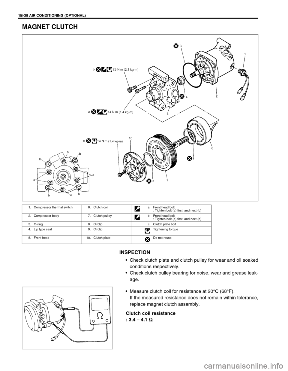
MAGNET CLUTCH
INSPECTION
Check clutch plate and clutch pulley for wear and oil soaked
conditions respectively.
Check clutch pulley bearing for noise, wear and grease leak-
age.
Measure clutch coil for resistance at 20°C (68°F).
If the measured resistance does not remain within tolerance,
replace magnet clutch assembly.
Clutch coil resistance
: 3.4 – 4.1
Ω
ΩΩ Ω
1. Compressor thermal switch 6. Clutch coil a. Front head bolt
: Tighten bolt (a) first, and next (b)
2. Compressor body 7. Clutch pulley b. Front head bolt
: Tighten bolt (a) first, and next (b)
3. O-ring 8. Circlip c. Clutch plate bolt
4. Lip type seal 9. Circlip Tightening torque
5. Front head 10. Clutch plate Do not reuse.
Page 107 of 698
1B-42 AIR CONDITIONING (OPTIONAL)
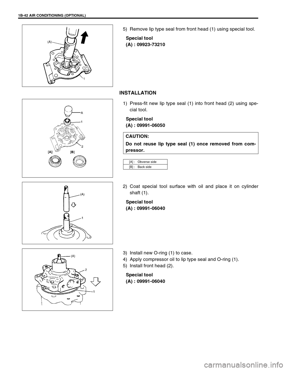
5) Remove lip type seal from front head (1) using special tool.
Special tool
(A) : 09923-73210
INSTALLATION
1) Press-fit new lip type seal (1) into front head (2) using spe-
cial tool.
Special tool
(A) : 09991-06050
2) Coat special tool surface with oil and place it on cylinder
shaft (1).
Special tool
(A) : 09991-06040
3) Install new O-ring (1) to case.
4) Apply compressor oil to lip type seal and O-ring (1).
5) Install front head (2).
Special tool
(A) : 09991-06040
CAUTION:
Do not reuse lip type seal (1) once removed from com-
pressor.
[A] : Obverse side
[B] : Back side
Page 215 of 698
3E-2 REAR SUSPENSION
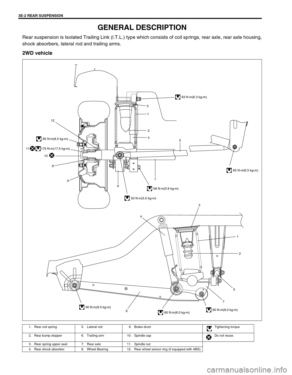
GENERAL DESCRIPTION
Rear suspension is Isolated Trailing Link (l.T.L.) type which consists of coil springs, rear axle, rear axle housing,
shock absorbers, lateral rod and trailing arms.
2WD vehicle
1. Rear coil spring 5. Lateral rod 9. Brake drum Tightening torque
2. Rear bump stopper 6. Trailing arm 10. Spindle cap Do not reuse.
3. Rear spring upper seat 7. Rear axle 11. Spindle nut
4. Rear shock absorber 8. Wheel Bearing 12. Rear wheel sensor ring (if equipped with ABS)
6752 1 3
4
3
5 1
2
4
63 N·m(6.3 kg-m)
65 N·m(6.5 kg-m)
58 N·m(5.8 kg-m)
50 N·m(5.0 kg-m)
90 N·m(9.0 kg-m)
80 N·m(8.0 kg-m)80 N·m(8.0 kg-m)
85 N·m(8.5 kg-m)
12
10
8
9
67
175 N·m(17.5 kg-m)11
Page 239 of 698
3E-26 REAR SUSPENSION
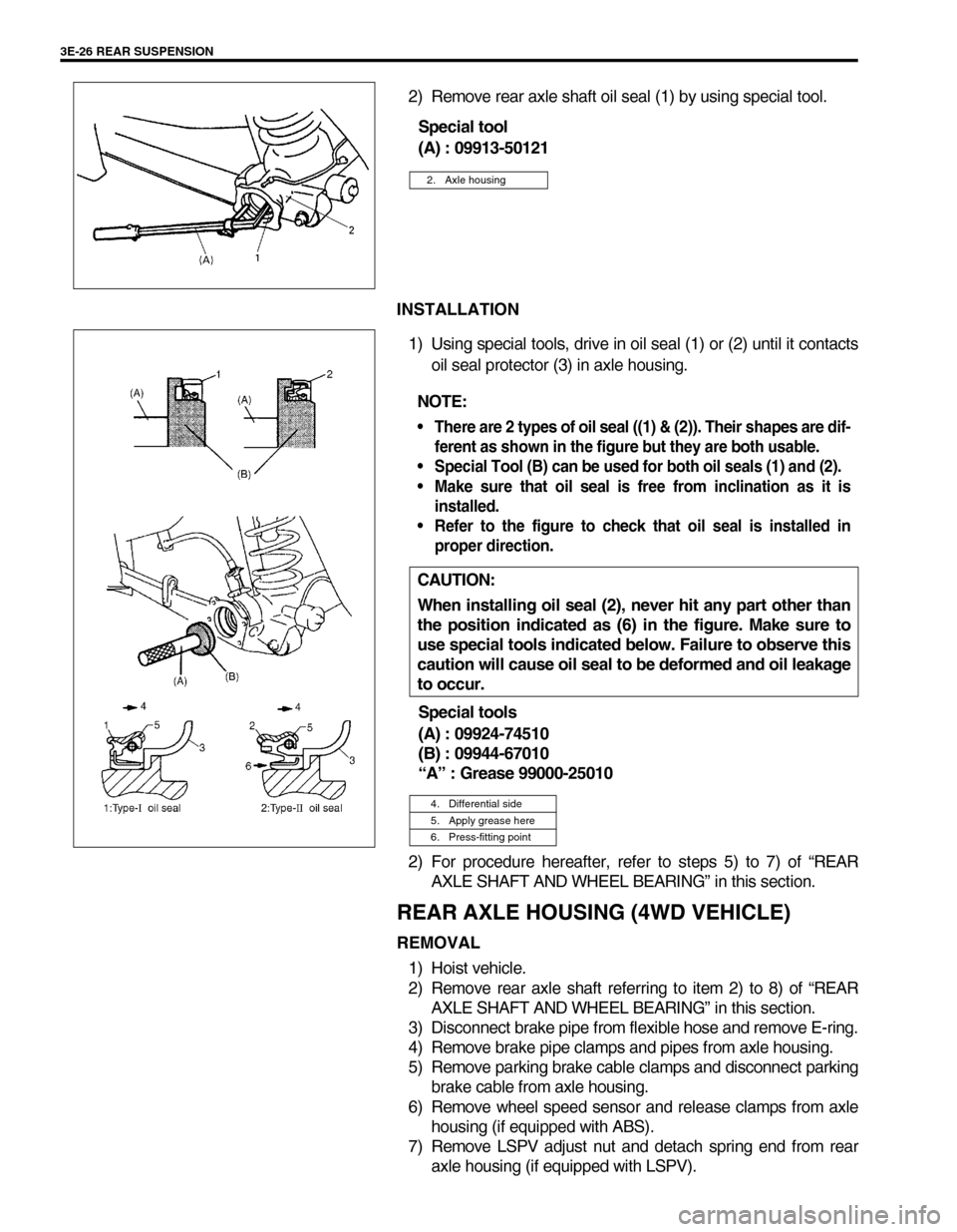
2) Remove rear axle shaft oil seal (1) by using special tool.
Special tool
(A) : 09913-50121
INSTALLATION
1) Using special tools, drive in oil seal (1) or (2) until it contacts
oil seal protector (3) in axle housing.
Special tools
(A) : 09924-74510
(B) : 09944-67010
“A” : Grease 99000-25010
2) For procedure hereafter, refer to steps 5) to 7) of “REAR
AXLE SHAFT AND WHEEL BEARING” in this section.
REAR AXLE HOUSING (4WD VEHICLE)
REMOVAL
1) Hoist vehicle.
2) Remove rear axle shaft referring to item 2) to 8) of “REAR
AXLE SHAFT AND WHEEL BEARING” in this section.
3) Disconnect brake pipe from flexible hose and remove E-ring.
4) Remove brake pipe clamps and pipes from axle housing.
5) Remove parking brake cable clamps and disconnect parking
brake cable from axle housing.
6) Remove wheel speed sensor and release clamps from axle
housing (if equipped with ABS).
7) Remove LSPV adjust nut and detach spring end from rear
axle housing (if equipped with LSPV).
2. Axle housing
NOTE:
There are 2 types of oil seal ((1) & (2)). Their shapes are dif-
ferent as shown in the figure but they are both usable.
Special Tool (B) can be used for both oil seals (1) and (2).
Make sure that oil seal is free from inclination as it is
installed.
Refer to the figure to check that oil seal is installed in
proper direction.
CAUTION:
When installing oil seal (2), never hit any part other than
the position indicated as (6) in the figure. Make sure to
use special tools indicated below. Failure to observe this
caution will cause oil seal to be deformed and oil leakage
to occur.
4. Differential side
5. Apply grease here
6. Press-fitting point
Page 256 of 698
FRONT DRIVE SHAFT 4A-3
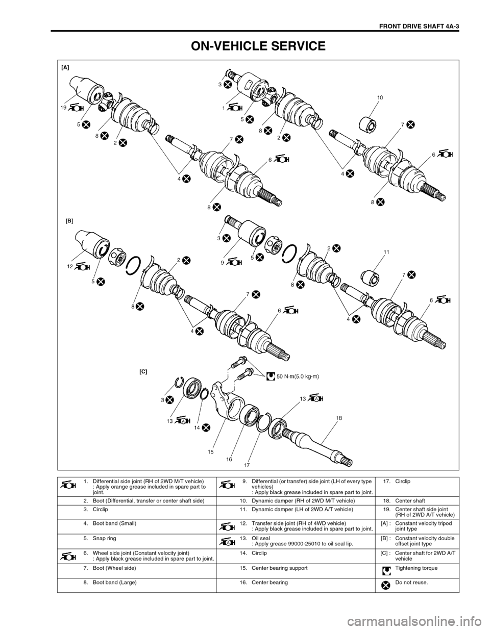
ON-VEHICLE SERVICE
1. Differential side joint (RH of 2WD M/T vehicle)
: Apply orange grease included in spare part to
joint.9. Differential (or transfer) side joint (LH of every type
vehicles)
: Apply black grease included in spare part to joint.17. Circlip
2. Boot (Differential, transfer or center shaft side) 10. Dynamic damper (RH of 2WD M/T vehicle) 18. Center shaft
3. Circlip 11. Dynamic damper (LH of 2WD A/T vehicle) 19. Center shaft side joint
(RH of 2WD A/T vehicle)
4. Boot band (Small) 12. Transfer side joint (RH of 4WD vehicle)
: Apply black grease included in spare part to joint.[A] : Constant velocity tripod
joint type
5. Snap ring 13. Oil seal
: Apply grease 99000-25010 to oil seal lip.[B] : Constant velocity double
offset joint type
6. Wheel side joint (Constant velocity joint)
: Apply black grease included in spare part to joint.14. Circlip [C] : Center shaft for 2WD A/T
vehicle
7. Boot (Wheel side) 15. Center bearing support Tightening torque
8. Boot band (Large) 16. Center bearing Do not reuse.
Page 269 of 698
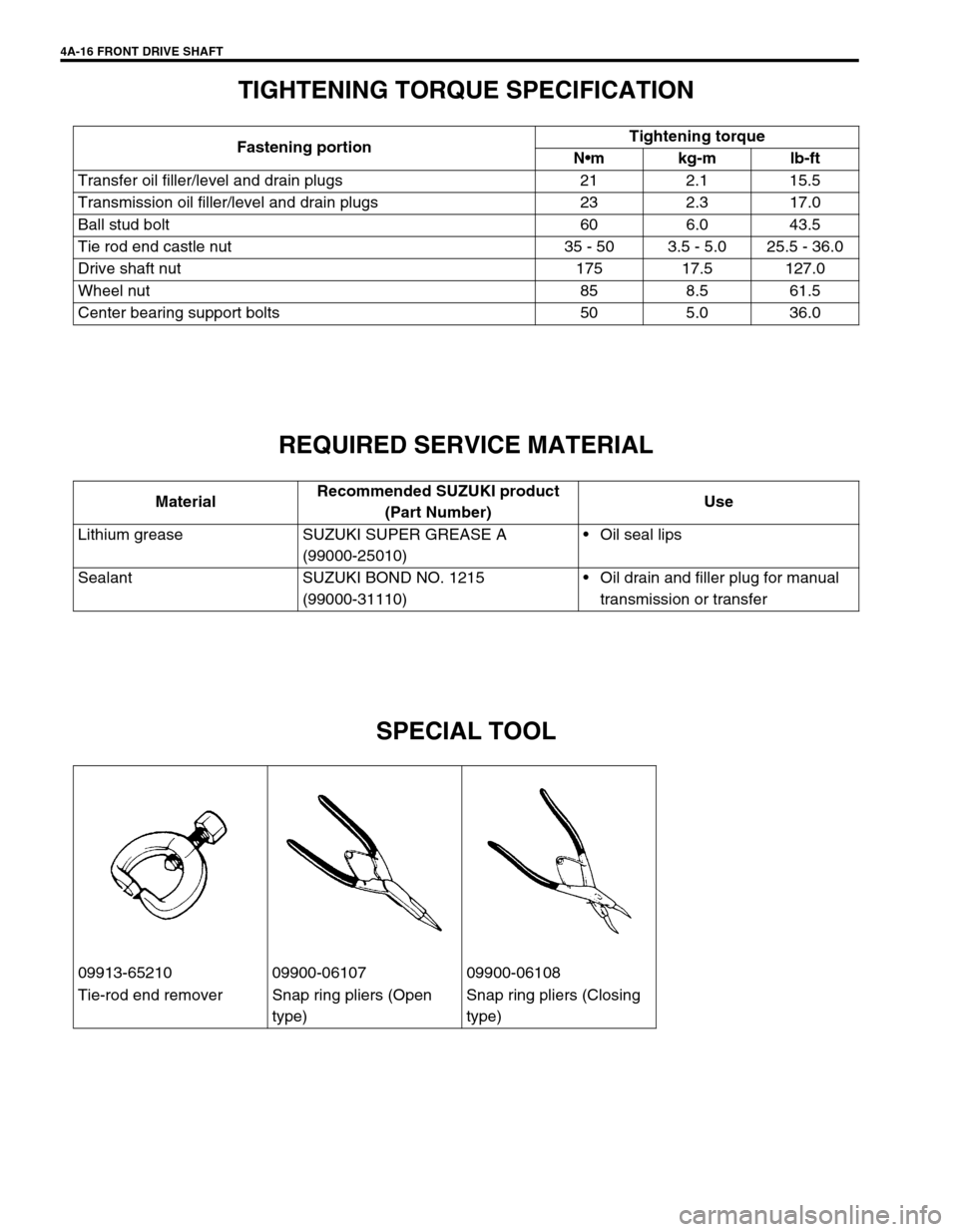
4A-16 FRONT DRIVE SHAFT
TIGHTENING TORQUE SPECIFICATION
REQUIRED SERVICE MATERIAL
SPECIAL TOOL
Fastening portionTightening torque
Nm kg-m lb-ft
Transfer oil filler/level and drain plugs 21 2.1 15.5
Transmission oil filler/level and drain plugs 23 2.3 17.0
Ball stud bolt 60 6.0 43.5
Tie rod end castle nut 35 - 50 3.5 - 5.0 25.5 - 36.0
Drive shaft nut 175 17.5 127.0
Wheel nut 85 8.5 61.5
Center bearing support bolts 50 5.0 36.0
MaterialRecommended SUZUKI product
(Part Number)Use
Lithium grease SUZUKI SUPER GREASE A
(99000-25010)Oil seal lips
Sealant SUZUKI BOND NO. 1215
(99000-31110)Oil drain and filler plug for manual
transmission or transfer
09913-65210 09900-06107 09900-06108
Tie-rod end remover Snap ring pliers (Open
type)Snap ring pliers (Closing
type)
Page 374 of 698
ENGINE GENERAL INFORMATION AND DIAGNOSIS 6-5
PRECAUTION ON FUEL SYSTEM SERVICE
Work must be done with no smoking, in a well-ventilated
area and away from any open flames.
As fuel feed line (between fuel pump and fuel delivery pipe)
is still under high fuel pressure even after engine was
stopped, loosening or disconnecting fuel feed line directly
may cause dangerous spout of fuel to occur where loosened
or disconnected.
Before loosening or disconnecting fuel feed line, make sure
to release fuel pressure according to “FUEL PRESSURE
RELIEF PROCEDURE”. A small amount of fuel may be
released after the fuel line is disconnected. In order to
reduce the chance of personal injury, cover the fitting to be
disconnected with a shop cloth. Put that cloth in an approved
container when disconnection is completed.
Never run engine with fuel pump relay disconnected when
engine and exhaust system are hot.
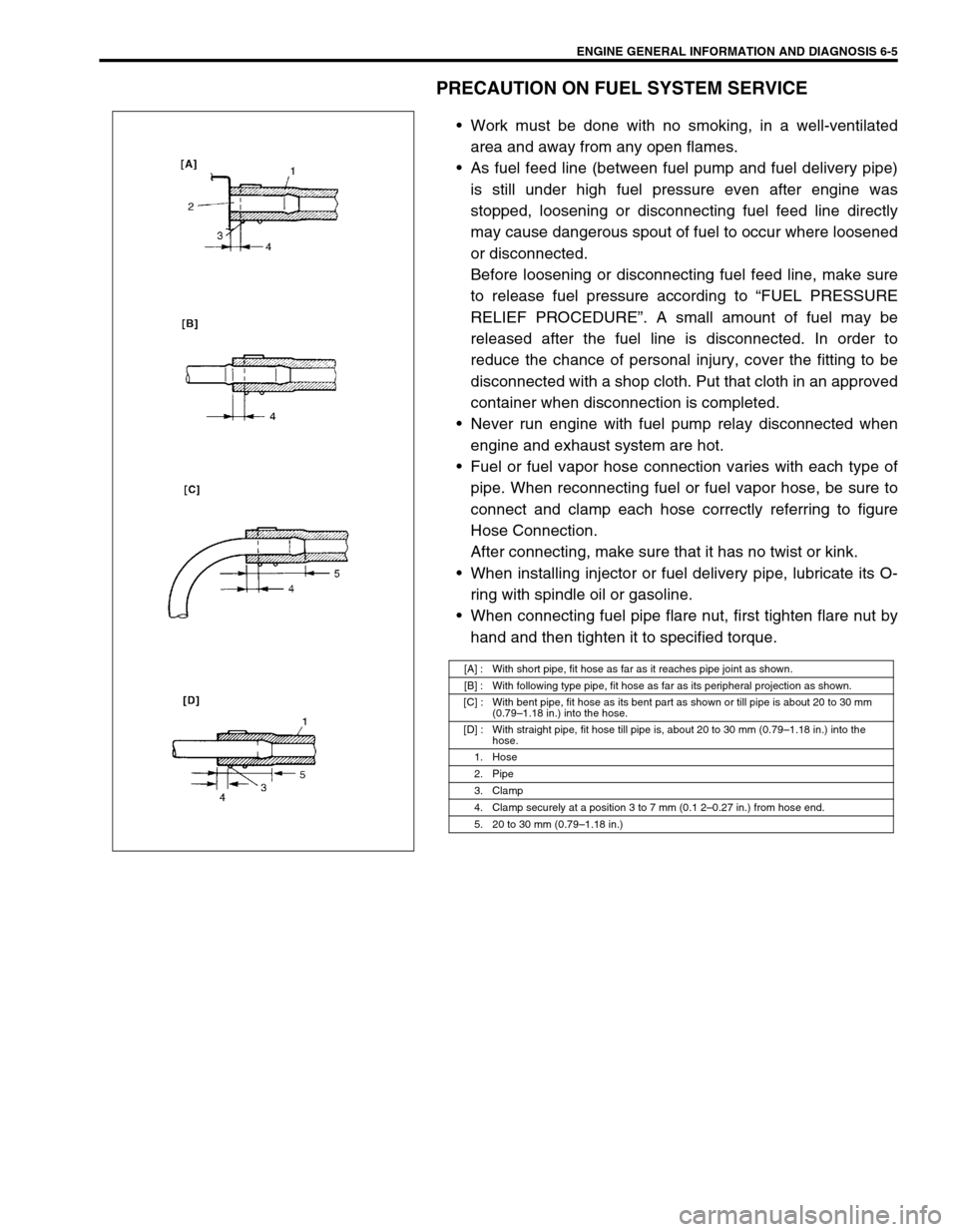
Fuel or fuel vapor hose connection varies with each type of
pipe. When reconnecting fuel or fuel vapor hose, be sure to
connect and clamp each hose correctly referring to figure
Hose Connection.
After connecting, make sure that it has no twist or kink.
When installing injector or fuel delivery pipe, lubricate its O-
ring with spindle oil or gasoline.
When connecting fuel pipe flare nut, first tighten flare nut by
hand and then tighten it to specified torque.
[A] : With short pipe, fit hose as far as it reaches pipe joint as shown.
[B] : With following type pipe, fit hose as far as its peripheral projection as shown.
[C] : With bent pipe, fit hose as its bent part as shown or till pipe is about 20 to 30 mm
(0.79–1.18 in.) into the hose.
[D] : With straight pipe, fit hose till pipe is, about 20 to 30 mm (0.79–1.18 in.) into the
hose.
1. Hose
2. Pipe
3. Clamp
4. Clamp securely at a position 3 to 7 mm (0.1 2–0.27 in.) from hose end.
5. 20 to 30 mm (0.79–1.18 in.)