run flat SUZUKI SWIFT 2000 1.G RG413 Service Workshop Manual
[x] Cancel search | Manufacturer: SUZUKI, Model Year: 2000, Model line: SWIFT, Model: SUZUKI SWIFT 2000 1.GPages: 698, PDF Size: 16.01 MB
Page 111 of 698
3-2 STEERING, SUSPENSION, WHEELS AND TIRES
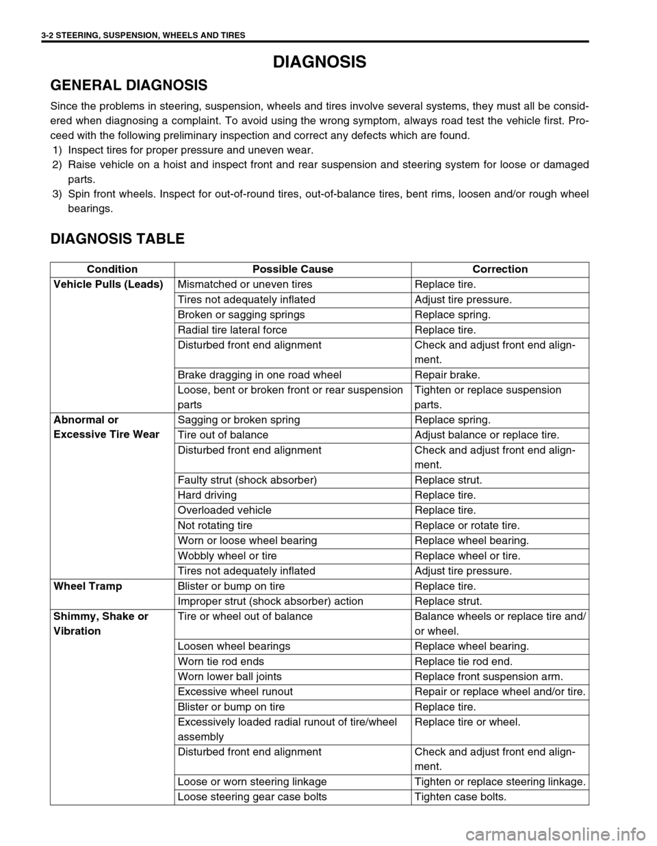
DIAGNOSIS
GENERAL DIAGNOSIS
Since the problems in steering, suspension, wheels and tires involve several systems, they must all be consid-
ered when diagnosing a complaint. To avoid using the wrong symptom, always road test the vehicle first. Pro-
ceed with the following preliminary inspection and correct any defects which are found.
1) Inspect tires for proper pressure and uneven wear.
2) Raise vehicle on a hoist and inspect front and rear suspension and steering system for loose or damaged
parts.
3) Spin front wheels. Inspect for out-of-round tires, out-of-balance tires, bent rims, loosen and/or rough wheel
bearings.
DIAGNOSIS TABLE
Condition Possible Cause Correction
Vehicle Pulls (Leads)
Mismatched or uneven tires Replace tire.
Tires not adequately inflated Adjust tire pressure.
Broken or sagging springs Replace spring.
Radial tire lateral force Replace tire.
Disturbed front end alignment Check and adjust front end align-
ment.
Brake dragging in one road wheel Repair brake.
Loose, bent or broken front or rear suspension
partsTighten or replace suspension
parts.
Abnormal or
Excessive Tire WearSagging or broken spring Replace spring.
Tire out of balance Adjust balance or replace tire.
Disturbed front end alignment Check and adjust front end align-
ment.
Faulty strut (shock absorber) Replace strut.
Hard driving Replace tire.
Overloaded vehicle Replace tire.
Not rotating tire Replace or rotate tire.
Worn or loose wheel bearing Replace wheel bearing.
Wobbly wheel or tire Replace wheel or tire.
Tires not adequately inflated Adjust tire pressure.
Wheel Tramp
Blister or bump on tire Replace tire.
Improper strut (shock absorber) action Replace strut.
Shimmy, Shake or
VibrationTire or wheel out of balance Balance wheels or replace tire and/
or wheel.
Loosen wheel bearings Replace wheel bearing.
Worn tie rod ends Replace tie rod end.
Worn lower ball joints Replace front suspension arm.
Excessive wheel runout Repair or replace wheel and/or tire.
Blister or bump on tire Replace tire.
Excessively loaded radial runout of tire/wheel
assemblyReplace tire or wheel.
Disturbed front end alignment Check and adjust front end align-
ment.
Loose or worn steering linkage Tighten or replace steering linkage.
Loose steering gear case bolts Tighten case bolts.
Page 113 of 698
3-4 STEERING, SUSPENSION, WHEELS AND TIRES
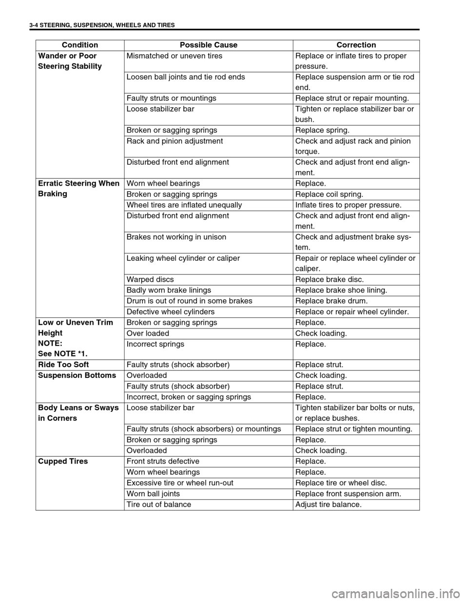
Wander or Poor
Steering StabilityMismatched or uneven tires Replace or inflate tires to proper
pressure.
Loosen ball joints and tie rod ends Replace suspension arm or tie rod
end.
Faulty struts or mountings Replace strut or repair mounting.
Loose stabilizer bar Tighten or replace stabilizer bar or
bush.
Broken or sagging springs Replace spring.
Rack and pinion adjustment Check and adjust rack and pinion
torque.
Disturbed front end alignment Check and adjust front end align-
ment.
Erratic Steering When
BrakingWorn wheel bearings Replace.
Broken or sagging springs Replace coil spring.
Wheel tires are inflated unequally Inflate tires to proper pressure.
Disturbed front end alignment Check and adjust front end align-
ment.
Brakes not working in unison Check and adjustment brake sys-
tem.
Leaking wheel cylinder or caliper Repair or replace wheel cylinder or
caliper.
Warped discs Replace brake disc.
Badly worn brake linings Replace brake shoe lining.
Drum is out of round in some brakes Replace brake drum.
Defective wheel cylinders Replace or repair wheel cylinder.
Low or Uneven Trim
Height
NOTE:
See NOTE *1.Broken or sagging springs Replace.
Over loaded Check loading.
Incorrect springs Replace.
Ride Too Soft
Faulty struts (shock absorber) Replace strut.
Suspension Bottoms
Overloaded Check loading.
Faulty struts (shock absorber) Replace strut.
Incorrect, broken or sagging springs Replace.
Body Leans or Sways
in CornersLoose stabilizer bar Tighten stabilizer bar bolts or nuts,
or replace bushes.
Faulty struts (shock absorbers) or mountings Replace strut or tighten mounting.
Broken or sagging springs Replace.
Overloaded Check loading.
Cupped Tires
Front struts defective Replace.
Worn wheel bearings Replace.
Excessive tire or wheel run-out Replace tire or wheel disc.
Worn ball joints Replace front suspension arm.
Tire out of balance Adjust tire balance. Condition Possible Cause Correction
Page 120 of 698
FRONT END ALIGNMENT 3A-3
DIAGNOSIS
DIAGNOSIS TABLE
For the details, refer to Section 3.
PRELIMINARY CHECKS PRIOR TO ADJUSTING FRONT ALIGNMENT
Steering and vibration complaints are not always the result of improper alignment. An additional item to be
checked is the possibility of tire lead due to worn or improperly manufactured tires. “Lead” is the deviation of the
vehicle from a straight path on a level road without hand pressure on the steering wheel. Procedure for deter-
mining the presence of a tire lead problem contains in SECTION 3. Before making any adjustment affecting toe
setting, the following checks and inspections should be made to ensure correctness of alignment readings and
alignment adjustments:
1) Check all tires for proper inflation pressures and approximately the same tread wear.
2) Check for loose of ball joints. Check tie rod ends; if excessive looseness is noted, it must be corrected
before adjusting.
3) Check for run-out of wheels and tires.
4) Check vehicle trim heights; if out of limits and a correction is to be made, it must be made before adjusting
toe.
5) Check for loose of suspension arms.
6) Check for loose or missing stabilizer bar attachments.
7) Consideration must be given to excess loads, such as tool boxes. If this excess load is normally carried in
vehicle, it should remain in vehicle during alignment checks.
8) Consider condition of equipment being used to check alignment and follow manufacturer's instructions.
9) Regardless of equipment used to check alignment, vehicle must be on a level surface both fore and aft and
transversely.
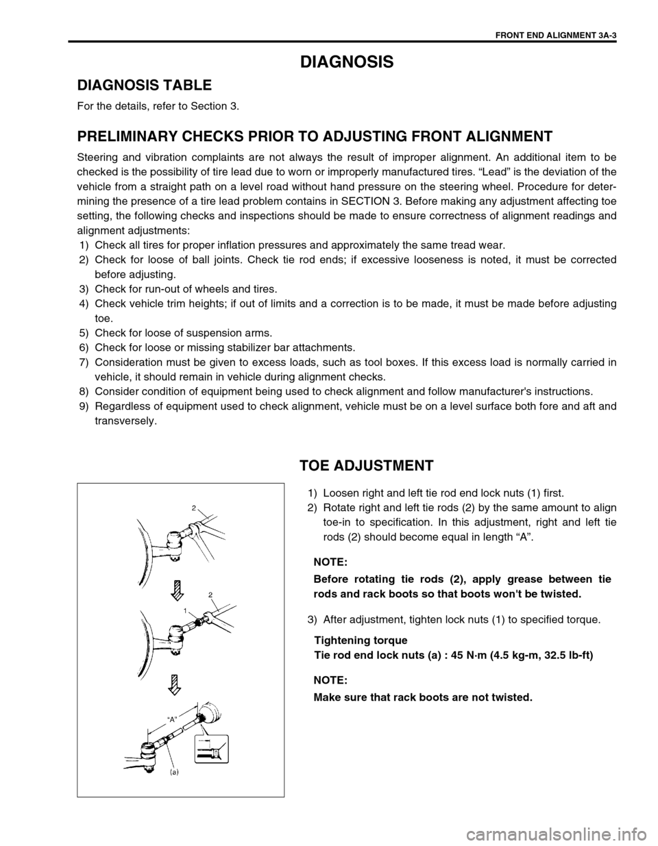
TOE ADJUSTMENT
1) Loosen right and left tie rod end lock nuts (1) first.
2) Rotate right and left tie rods (2) by the same amount to align
toe-in to specification. In this adjustment, right and left tie
rods (2) should become equal in length “A”.
3) After adjustment, tighten lock nuts (1) to specified torque.
Tightening torque
Tie rod end lock nuts (a) : 45 N·m (4.5 kg-m, 32.5 lb-ft) NOTE:
Before rotating tie rods (2), apply grease between tie
rods and rack boots so that boots won't be twisted.
NOTE:
Make sure that rack boots are not twisted.
Page 246 of 698
WHEELS AND TIRES 3F-1
6F1
6F2
6G
3F
8A
8B
8C
8D
8E
9
10
10A
10B
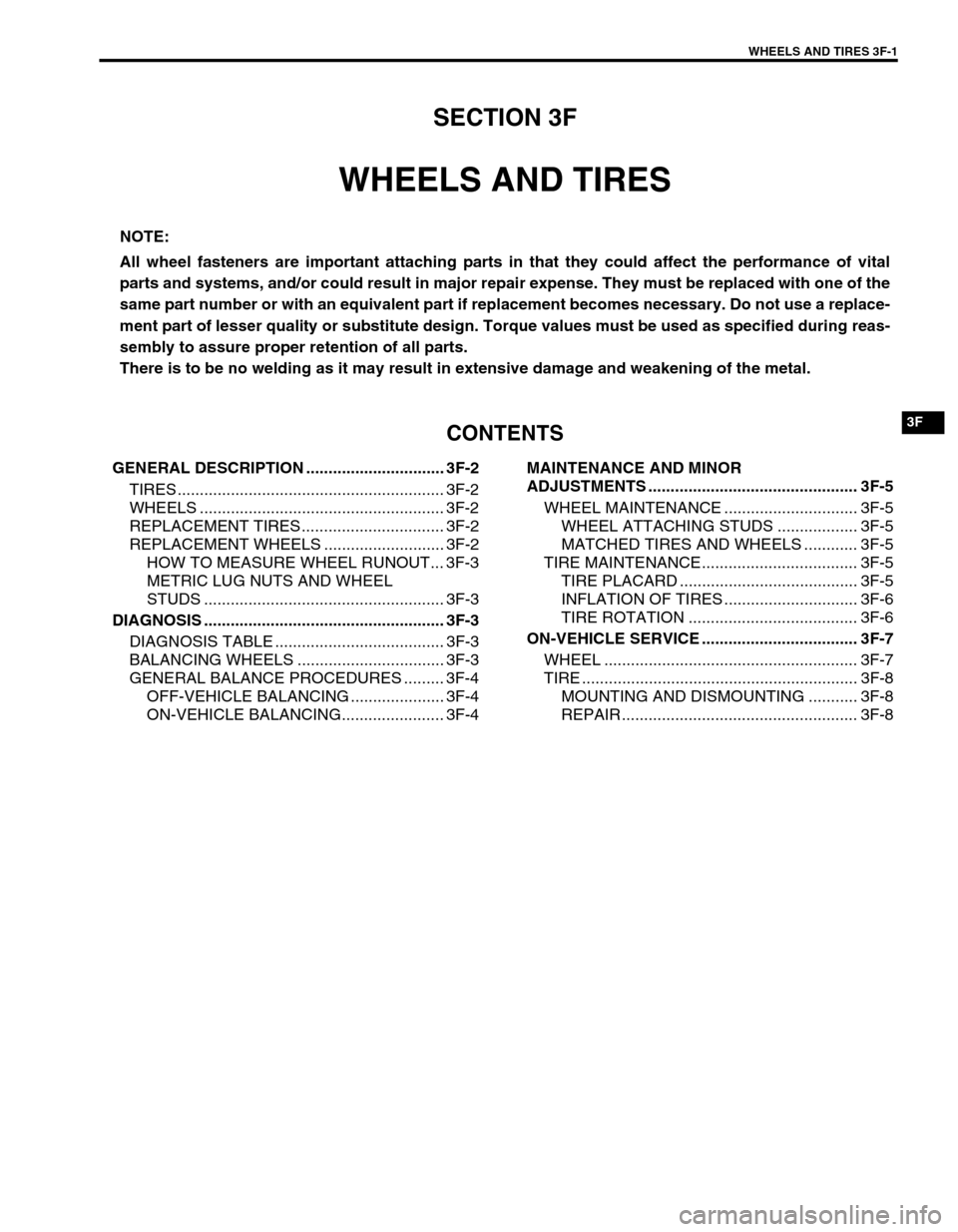
SECTION 3F
WHEELS AND TIRES
CONTENTS
GENERAL DESCRIPTION ............................... 3F-2
TIRES ............................................................ 3F-2
WHEELS ....................................................... 3F-2
REPLACEMENT TIRES ................................ 3F-2
REPLACEMENT WHEELS ........................... 3F-2
HOW TO MEASURE WHEEL RUNOUT... 3F-3
METRIC LUG NUTS AND WHEEL
STUDS ...................................................... 3F-3
DIAGNOSIS ...................................................... 3F-3
DIAGNOSIS TABLE ...................................... 3F-3
BALANCING WHEELS ................................. 3F-3
GENERAL BALANCE PROCEDURES ......... 3F-4
OFF-VEHICLE BALANCING ..................... 3F-4
ON-VEHICLE BALANCING....................... 3F-4MAINTENANCE AND MINOR
ADJUSTMENTS ............................................... 3F-5
WHEEL MAINTENANCE .............................. 3F-5
WHEEL ATTACHING STUDS .................. 3F-5
MATCHED TIRES AND WHEELS ............ 3F-5
TIRE MAINTENANCE................................... 3F-5
TIRE PLACARD ........................................ 3F-5
INFLATION OF TIRES .............................. 3F-6
TIRE ROTATION ...................................... 3F-6
ON-VEHICLE SERVICE ................................... 3F-7
WHEEL ......................................................... 3F-7
TIRE .............................................................. 3F-8
MOUNTING AND DISMOUNTING ........... 3F-8
REPAIR ..................................................... 3F-8
NOTE:
All wheel fasteners are important attaching parts in that they could affect the performance of vital
parts and systems, and/or could result in major repair expense. They must be replaced with one of the
same part number or with an equivalent part if replacement becomes necessary. Do not use a replace-
ment part of lesser quality or substitute design. Torque values must be used as specified during reas-
sembly to assure proper retention of all parts.
There is to be no welding as it may result in extensive damage and weakening of the metal.
Page 247 of 698
3F-2 WHEELS AND TIRES
GENERAL DESCRIPTION
TIRES
This vehicle is equipped with the following tire.
Tire size
: 165/70R14
The tire is of tubeless type. The tire is designed to operate satisfactorily with loads up to the full rated load
capacity when inflated to the recommended inflation pressures.
Correct tire pressures and driving habits have an important influence on tire life. Heavy cornering, excessively
rapid acceleration, and unnecessary sharp braking increase tire wear.
WHEELS
Standard equipment wheels are the following steel wheel.
Wheel size
: 14 x 4 1/2 J
REPLACEMENT TIRES
When replacement is necessary, the original equipment type tire should be used. Refer to the “Tire Placard”.
Replacement tires should be of the same size, load range and construction as those originally on the vehicle.
Use of any other size or type tire may affect ride, handling, speedometer/odometer calibration, vehicle ground
clearance and tire or snow chain clearance to the body and chassis.
It is recommended that new tires be installed in pairs on the same axle. If necessary to replace only one tire, it
should be paired with the tire having the most tread, to equalize braking traction.
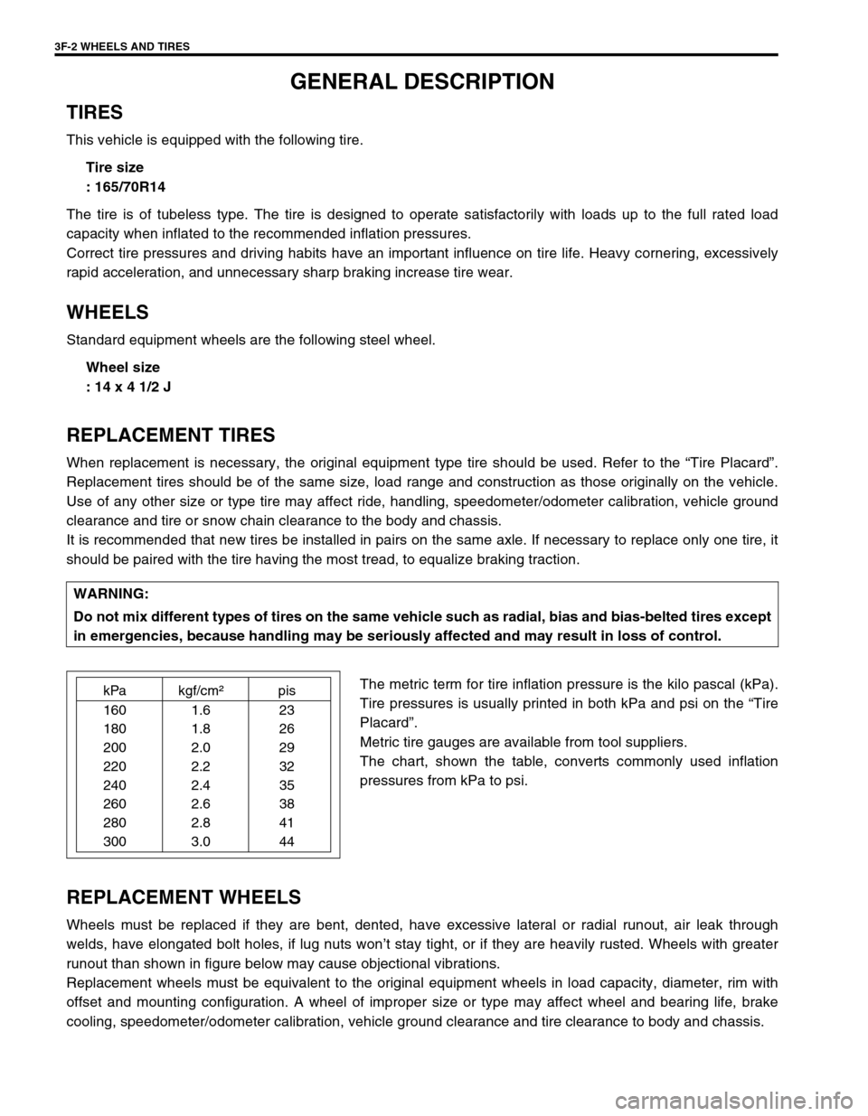
The metric term for tire inflation pressure is the kilo pascal (kPa).
Tire pressures is usually printed in both kPa and psi on the “Tire
Placard”.
Metric tire gauges are available from tool suppliers.
The chart, shown the table, converts commonly used inflation
pressures from kPa to psi.
REPLACEMENT WHEELS
Wheels must be replaced if they are bent, dented, have excessive lateral or radial runout, air leak through
welds, have elongated bolt holes, if lug nuts won’t stay tight, or if they are heavily rusted. Wheels with greater
runout than shown in figure below may cause objectional vibrations.
Replacement wheels must be equivalent to the original equipment wheels in load capacity, diameter, rim with
offset and mounting configuration. A wheel of improper size or type may affect wheel and bearing life, brake
cooling, speedometer/odometer calibration, vehicle ground clearance and tire clearance to body and chassis.WARNING:
Do not mix different types of tires on the same vehicle such as radial, bias and bias-belted tires except
in emergencies, because handling may be seriously affected and may result in loss of control.
kPa kgf/cm²pis
160 1.6 23
180 1.8 26
200 2.0 29
220 2.2 32
240 2.4 35
260 2.6 38
280 2.8 41
300 3.0 44