battery replacement SUZUKI SWIFT 2000 1.G Transmission Service Workshop Manual
[x] Cancel search | Manufacturer: SUZUKI, Model Year: 2000, Model line: SWIFT, Model: SUZUKI SWIFT 2000 1.GPages: 447, PDF Size: 10.54 MB
Page 66 of 447

7B-24 AUTOMATIC TRANSMISSION (4 A/T)
ELECTRONIC CONTROL SYSTEM DIAGNO-
SIS
TCM has on-board diagnostic system (a system self-diagnosis
function). Investigate where the trouble is by referring to “DIAG-
NOSTIC FLOW TABLE” and “DTC TABLE” in this section.
PRECAUTIONS IN DIAGNOSING TROUBLES
[PRECAUTIONS IN IDENTIFYING DTC]
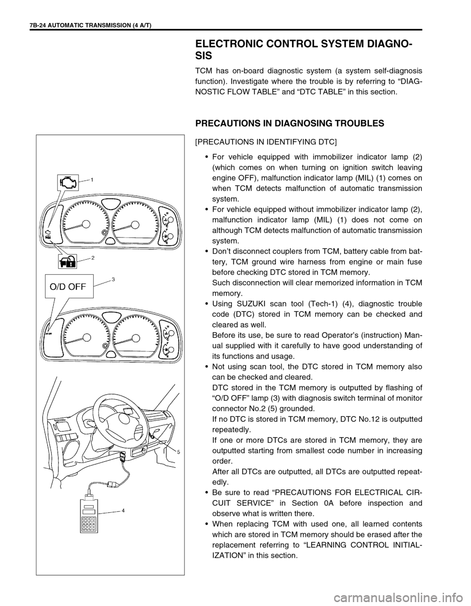
For vehicle equipped with immobilizer indicator lamp (2)
(which comes on when turning on ignition switch leaving
engine OFF), malfunction indicator lamp (MIL) (1) comes on
when TCM detects malfunction of automatic transmission
system.
For vehicle equipped without immobilizer indicator lamp (2),
malfunction indicator lamp (MIL) (1) does not come on
although TCM detects malfunction of automatic transmission
system.
Don’t disconnect couplers from TCM, battery cable from bat-
tery, TCM ground wire harness from engine or main fuse
before checking DTC stored in TCM memory.
Such disconnection will clear memorized information in TCM
memory.
Using SUZUKI scan tool (Tech-1) (4), diagnostic trouble
code (DTC) stored in TCM memory can be checked and
cleared as well.
Before its use, be sure to read Operator’s (instruction) Man-
ual supplied with it carefully to have good understanding of
its functions and usage.
Not using scan tool, the DTC stored in TCM memory also
can be checked and cleared.
DTC stored in the TCM memory is outputted by flashing of
“O/D OFF” lamp (3) with diagnosis switch terminal of monitor
connector No.2 (5) grounded.
If no DTC is stored in TCM memory, DTC No.12 is outputted
repeatedly.
If one or more DTCs are stored in TCM memory, they are
outputted starting from smallest code number in increasing
order.
After all DTCs are outputted, all DTCs are outputted repeat-
edly.
Be sure to read “PRECAUTIONS FOR ELECTRICAL CIR-
CUIT SERVICE” in Section 0A before inspection and
observe what is written there.
When replacing TCM with used one, all learned contents
which are stored in TCM memory should be erased after the
replacement referring to “LEARNING CONTROL INITIAL-
IZATION” in this section.
Page 254 of 447

8-10 BODY ELECTRICAL SYSTEM
INSPECTION
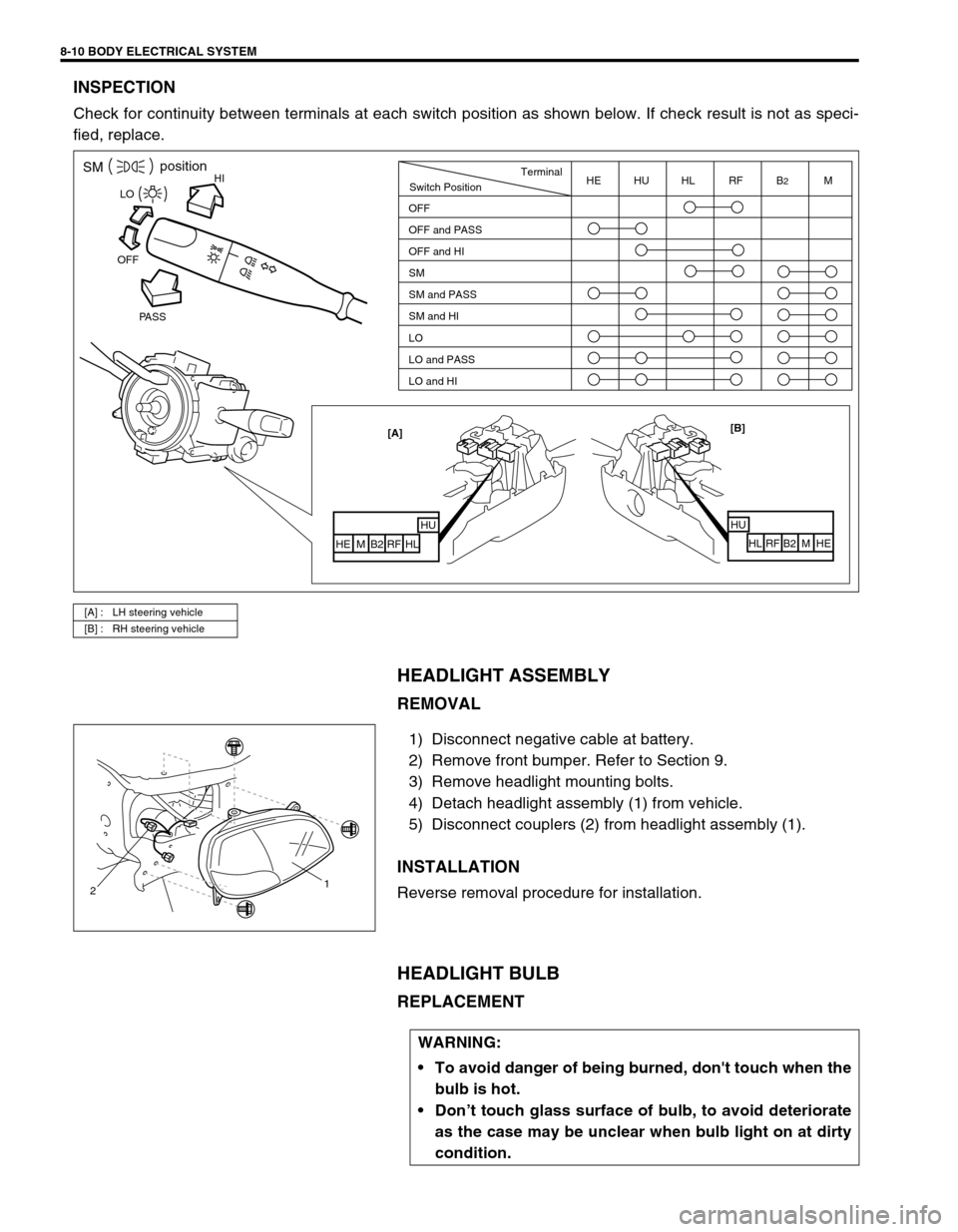
Check for continuity between terminals at each switch position as shown below. If check result is not as speci-
fied, replace.
HEADLIGHT ASSEMBLY
REMOVAL
1) Disconnect negative cable at battery.
2) Remove front bumper. Refer to Section 9.
3) Remove headlight mounting bolts.
4) Detach headlight assembly (1) from vehicle.
5) Disconnect couplers (2) from headlight assembly (1).
INSTALLATION
Reverse removal procedure for installation.
HEADLIGHT BULB
REPLACEMENT
[A] : LH steering vehicle
[B] : RH steering vehicle
HISMposition
PASS OFFLO
[B]
HU
HL RF B2 M HE [A]
HUHL
RF B2 M HE
Switch PositionTerminal
OFF
OFF and PASS
OFF and HI
SM
SM and PASS
SM and HI
LO
LO and PASS
LO and HIHE HU HL RF B2M
21
WARNING:
To avoid danger of being burned, don't touch when the
bulb is hot.
Don’t touch glass surface of bulb, to avoid deteriorate
as the case may be unclear when bulb light on at dirty
condition.
Page 274 of 447

8-30 BODY ELECTRICAL SYSTEM
RECEIVER
INSPECTION
Check voltage between each terminal and body ground with con-
necting controller coupler. If check result is not as specified,
replace.
Receiver specification
Reference :
TRANSMITTER
REPLACEMEMT OF THE BATTERY
If the transmitter becomes unreliable, replace the battery.
As the battery power is consumed, the operation distance will be
shorter.
1) Remove screw.
2) Use a small coin or flat blade screwdriver to separate the
bottom half from the top half of the transmitter.
3) Replace the battery with the new one. Make sure the posi-
tive (+) side of battery faces up. For battery replacement,
use type CR2032 or equivalent.
4) Put the two halves back together and install a screw.
5) Make sure the door locks can be operated with the transmit-
ter. Terminal Voltage (V) Condition
B10 - 14Always
SIG“A”
(Refer to the figure)Approx. 75 ms while trans-
mitter signal received
5Other condition than above
mentioned
GND 0 Always
1. Receiver
2. Receiver coupler (receiver side)
Page 300 of 447

8G-22 IMMOBILIZER CONTROL SYSTEM
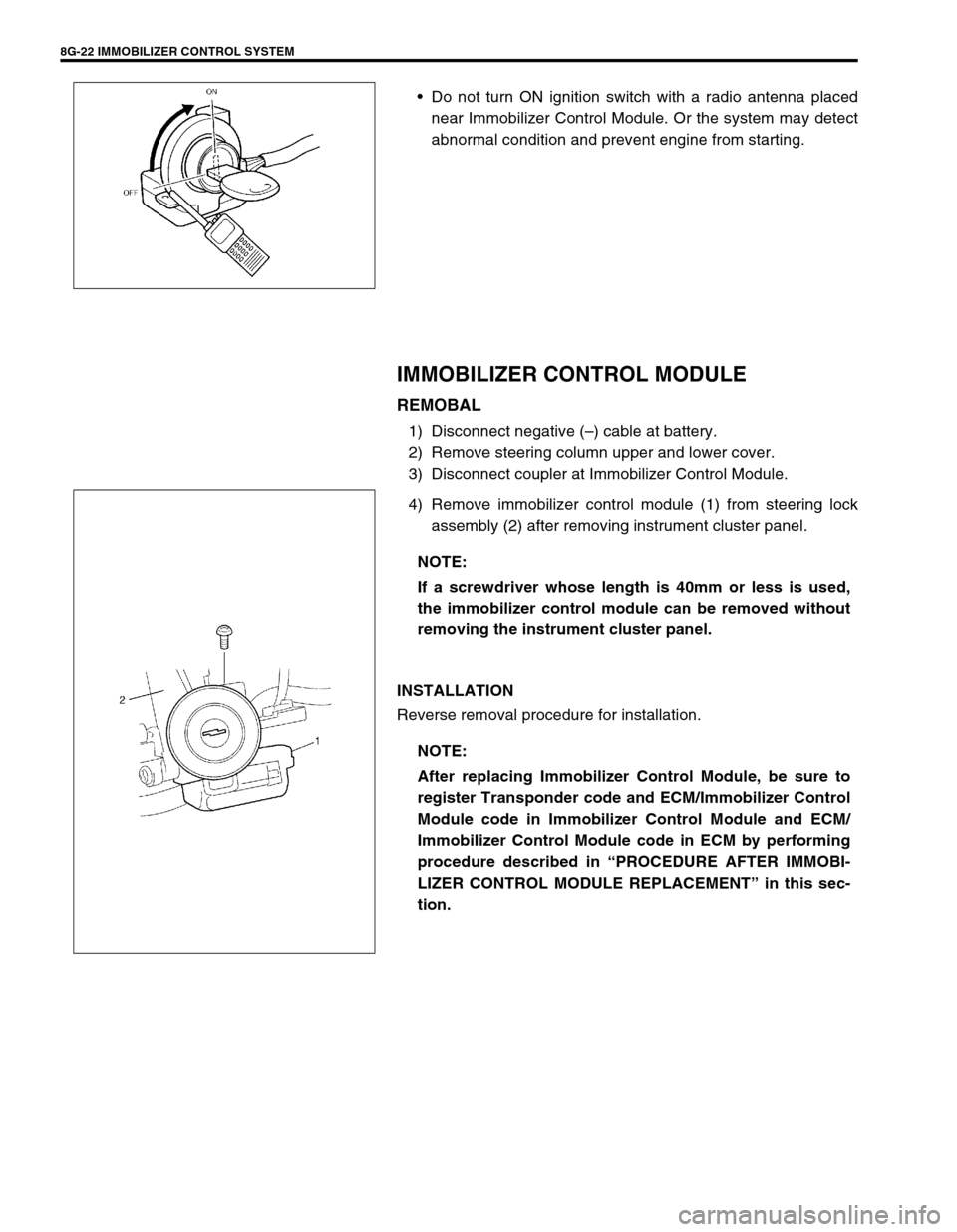
Do not turn ON ignition switch with a radio antenna placed
near Immobilizer Control Module. Or the system may detect
abnormal condition and prevent engine from starting.
IMMOBILIZER CONTROL MODULE
REMOBAL
1) Disconnect negative (–) cable at battery.
2) Remove steering column upper and lower cover.
3) Disconnect coupler at Immobilizer Control Module.
4) Remove immobilizer control module (1) from steering lock
assembly (2) after removing instrument cluster panel.
INSTALLATION
Reverse removal procedure for installation.
NOTE:
If a screwdriver whose length is 40mm or less is used,
the immobilizer control module can be removed without
removing the instrument cluster panel.
NOTE:
After replacing Immobilizer Control Module, be sure to
register Transponder code and ECM/Immobilizer Control
Module code in Immobilizer Control Module and ECM/
Immobilizer Control Module code in ECM by performing
procedure described in “PROCEDURE AFTER IMMOBI-
LIZER CONTROL MODULE REPLACEMENT” in this sec-
tion.
Page 305 of 447

BODY SERVICE 9-1
6F1
6F2
6G
6H
6K
7A
7A1
7B1
7C1
7D
7E
7F
8A
8B
8C
8D
8E
9
10
10A
10B
SECTION 9
BODY SERVICE
CONTENTS
GLASS, WINDOWS AND MIRRORS ................. 9-2
FRONT DOOR GLASS ................................... 9-2
FRONT DOOR WINDOW REGULATOR ........ 9-6
DOOR MIRROR .......................................... 9-7
REAR DOOR GLASS (IF EQUIPPED) ....... 9-8
REAR DOOR WINDOW REGULATOR ........ 9-11
WINDOW SHIELD ........................................ 9-12
QUARTER WINDOW .................................... 9-17
BACK DOOR GLASS .................................... 9-18
BODY STRUCTURE......................................... 9-19
FRONT DOOR ASSEMBLY .......................... 9-19
REAR DOOR ASSEMBLY ............................ 9-22
BACK DOOR ASSEMBLY ............................ 9-23
HOOD ........................................................... 9-25
FRONT FENDER .......................................... 9-26
FRONT BUMPER AND REAR BUMPER...... 9-27
ROOF RAIL (IF EQUIPPED) ......................... 9-28
BODY DIMENSIONS .................................... 9-29
ENGINE ROOM ........................................ 9-29
BACK DOOR ............................................. 9-30
SIDE BODY ............................................... 9-31UNDER BODY .......................................... 9-34
PANEL CLEARANCE ................................... 9-36
INSTRUMENTATION AND DRIVER
INFORMATION................................................. 9-38
INSTRUMENT PANEL .................................. 9-38
SEATS .............................................................. 9-40
FRONT SEAT ............................................... 9-40
REAR SEAT.................................................. 9-41
SECURITY AND LOCKS ................................. 9-42
FRONT DOOR LOCK ASSEMBLY............... 9-42
REAR DOOR LOCK ASSEMBLY (IF
EQUIPPED) .................................................. 9-44
BACK DOOR LOCK ASSEMBLY ................. 9-45
KEY CODING ............................................... 9-46
KEY USAGE AND IDENTIFICATION ....... 9-46
IGNITION SWITCH LOCK CYLINDER ..... 9-47
EXTERIOR AND INTERIOR TRIM ................... 9-47
FLOOR CARPET .......................................... 9-47
HEAD LINING ............................................... 9-48
PAINT AND COATINGS .................................. 9-50 WARNING:
For vehicles equipped with Supplemental Restraint (Air Bag) System:
Service on and around the air bag system components or wiring must be performed only by an
authorized SUZUKI dealer. Refer to “Air Bag System Components and Wiring Location View” under
“General Description” in air bag system section in order to confirm whether you are performing ser-
vice on or near the air bag system components or wiring. Please observe all WARNINGS and “Ser-
vice Precautions” under “On-Vehicle Service” in air bag system section before performing service
on or around the air bag system components or wiring. Failure to follow WARNINGS could result in
unintentional activation of the system or could render the system inoperative. Either of these two
conditions may result in severe injury.
Technical service work must be started at least 90 seconds after the ignition switch is turned to the
“LOCK” position and the negative cable is disconnected from the battery. Otherwise, the system
may be activated by reserve energy in the Sensing and Diagnostic Module (SDM).
When body servicing, if shock may be applied to air bag system component parts, remove those
parts beforehand. (Refer to Section 10B.)
NOTE:
Fasteners are important attaching parts in that they could affect the performance of vital components
and systems, and / or could result in major repair expense. They must be replaced with one of the
same part number of with an equivalent part if replacement becomes necessary.
Do not use a replacement part of lesser quality or substitute a design. Torque values must be used as
specified during reassembly to assure proper retention of these parts.
Page 383 of 447

AIR BAG SYSTEM 10B-9
AIR BAG DIAGNOSTIC SYSTEM CHECK
The diagnostic procedures used in this section are designed to find and repair air bag system malfunctions.
To get the best results, it is important to use the diagnostic flow tables and follow the sequence listed below.
1) Perform the AIR BAG DIAGNOSTIC SYSTEM CHECK FLOW TABLE.
(The AIR BAG DIAGNOSTIC SYSTEM CHECK FLOW TABLE must be the starting point of any air bag sys-
tem diagnosis.
The AIR BAG DIAGNOSTIC SYSTEM CHECK FLOW TABLE checks for proper “AIR BAG” warning lamp
operation through “AIR BAG” warning lamp and whether air bag diagnostic trouble codes exist.)
2) Refer to the proper diagnostic table as directed by the AIR BAG DIAGNOSTIC SYSTEM CHECK FLOW
TABLE.
(The AIR BAG DIAGNOSTIC SYSTEM CHECK FLOW TABLE will lead you to the correct table to diagnose
any air bag system malfunctions. Bypassing these procedures may result in extended diagnostic time, incor-
rect diagnosis and incorrect parts replacement.)
3) Repeat the AIR BAG DIAGNOSTIC SYSTEM CHECK FLOW TABLE after any repair or diagnostic proce-
dures have been performed.
(Performing the AIR BAG DIAGNOSTIC SYSTEM CHECK FLOW TABLE after all repair or diagnostic pro-
cedures will ensure that the repair has been made correctly and that no other malfunctions exist.)
FLOW TABLE TEST DESCRIPTION
STEP 1 : Check that “AIR BAG” warning lamp lights.
STEP 2 : Check that “AIR BAG” warning lamp lights.
STEP 3 : Check diagnosis switch circuit.
STEP 4 : Check that “AIR BAG” warning lamp flashes 6 times after ignition switch is turned ON.
STEP 6 : Check that history codes are in SDM memory. (using SUZUKI scan tool)
STEP 7 : Check that history codes are in SDM memory. (using monitor coupler)
STEP 9 : Check that current code is in SDM memory. (using SUZUKI scan tool)
STEP 10 : Check that current code is in SDM memory. (using monitor coupler)WARNING:
To avoid deployment when troubleshooting the air bag system, do not use electrical test equipment
such as a battery powered or AC powered voltmeter, ohmmeter, etc., or any type of electrical equip-
ment other than that specified in this manual. Do not use a non-powered probe type tester.
Instructions in this manual must be followed carefully, otherwise personal injury may result.
CAUTION:
The order in which diagnostic trouble codes are diagnosed is very important. Failure to diagnose the
diagnostic trouble codes in the order specified may result in extended diagnostic time, incorrect diag-
nosis and incorrect parts replacement.