bulb SUZUKI SWIFT 2000 1.G Transmission Service Workshop Manual
[x] Cancel search | Manufacturer: SUZUKI, Model Year: 2000, Model line: SWIFT, Model: SUZUKI SWIFT 2000 1.GPages: 447, PDF Size: 10.54 MB
Page 245 of 447
BODY ELECTRICAL SYSTEM 8-1
6F1
6F2
6G
6H
6K
7A
7A1
7B1
7C1
7D
7E
7F
8A
8
8D
8E
9
10
10A
10B
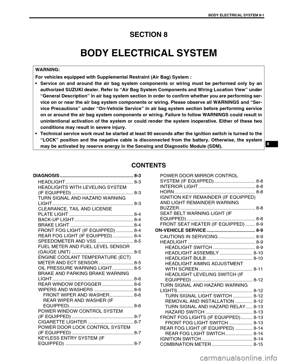
SECTION 8
BODY ELECTRICAL SYSTEM
CONTENTS
DIAGNOSIS ........................................................ 8-3
HEADLIGHT .................................................... 8-3
HEADLIGHTS WITH LEVELING SYSTEM
(IF EQUIPPED) ............................................... 8-3
TURN SIGNAL AND HAZARD WARNING
LIGHT .............................................................. 8-3
CLEARANCE, TAIL AND LICENSE
PLATE LIGHT ................................................. 8-4
BACK-UP LIGHT ............................................. 8-4
BRAKE LIGHT ................................................ 8-4
FRONT FOG LIGHT (IF EQUIPPED) ............. 8-4
REAR FOG LIGHT (IF EQUIPPED) ................ 8-4
SPEEDOMETER AND VSS ............................ 8-5
FUEL METER AND FUEL LEVEL SENSOR
(GAUGE UNIT) ............................................... 8-5
ENGINE COOLANT TEMPERATURE (ECT)
METER AND ECT SENSOR ........................... 8-5
OIL PRESSURE WARNING LIGHT ................ 8-5
BRAKE AND PARKING BRAKE WARNING
LIGHT .............................................................. 8-6
REAR WINDOW DEFOGGER ........................ 8-6
WIPERS AND WASHERS .............................. 8-6
FRONT WIPER AND WASHER .................. 8-6
REAR WIPER AND WASHER (IF
EQUIPPED)................................................. 8-6
POWER WINDOW CONTROL SYSTEM
(IF EQUIPPED) ............................................... 8-7
CIGARETTE LIGHTER ................................... 8-7
POWER DOOR LOCK CONTROL SYSTEM
(IF EQUIPPED) ............................................... 8-7
KEYLESS ENTRY SYSTEM (IF
EQUIPPED) .................................................... 8-7POWER DOOR MIRROR CONTROL
SYSTEM (IF EQUIPPED) ............................... 8-8
INTERIOR LIGHT ........................................... 8-8
HORN ............................................................. 8-8
IGNITION KEY REMAINDER (IF EQUIPPED)
AND LIGHT REMAINDER WARNING
BUZZER.......................................................... 8-8
SEAT BELT WARNING LIGHT (IF
EQUIPPED) .................................................... 8-8
FRONT SEAT HEATER (IF EQUIPPED) ....... 8-9
ON-VEHICLE SERVICE ..................................... 8-9
CAUTIONS IN SERVICING ............................ 8-9
HEADLIGHT ................................................... 8-9
HEADLIGHT SWITCH ................................ 8-9
HEADLIGHT ASSEMBLY ......................... 8-10
HEADLIGHT BULB ................................... 8-10
HEADLIGHT AIMING ADJUSTMENT
WITH SCREEN ......................................... 8-11
HEADLIGHT LEVELING SWITCH (IF
EQUIPPED) .............................................. 8-12
TURN SIGNAL AND HAZARD WARNING
LIGHTS ......................................................... 8-12
TURN SIGNAL LIGHT SWITCH ............... 8-12
REMOVAL AND INSTALLATION ............. 8-12
TURN SIGNAL AND HAZARD RELAY ..... 8-13
HAZARD SWITCH .................................... 8-13
FRONT FOG LIGHTS (IF EQUIPPED)......... 8-13
FRONT FOG LIGHT SWITCH .................. 8-13
REAR FOG LIGHT (IF EQUIPPED) ............. 8-14
REAR FOG LIGHT SWITCH..................... 8-14
IGNITION SWITCH ....................................... 8-14
COMBINATION METER ............................... 8-15 WARNING:
For vehicles equipped with Supplemental Restraint (Air Bag) System :
Service on and around the air bag system components or wiring must be performed only by an
authorized SUZUKI dealer. Refer to “Air Bag System Components and Wiring Location View” under
“General Description” in air bag system section in order to confirm whether you are performing ser-
vice on or near the air bag system components or wiring. Please observe all WARNINGS and “Ser-
vice Precautions” under “On-Vehicle Service” in air bag system section before performing service
on or around the air bag system components or wiring. Failure to follow WARNINGS could result in
unintentional activation of the system or could render the system inoperative. Either of these two
conditions may result in severe injury.
Technical service work must be started at least 90 seconds after the ignition switch is turned to the
“LOCK” position and the negative cable is disconnected from the battery. Otherwise, the system
may be activated by reserve energy in the Sensing and Diagnostic Module (SDM).
Page 247 of 447
BODY ELECTRICAL SYSTEM 8-3
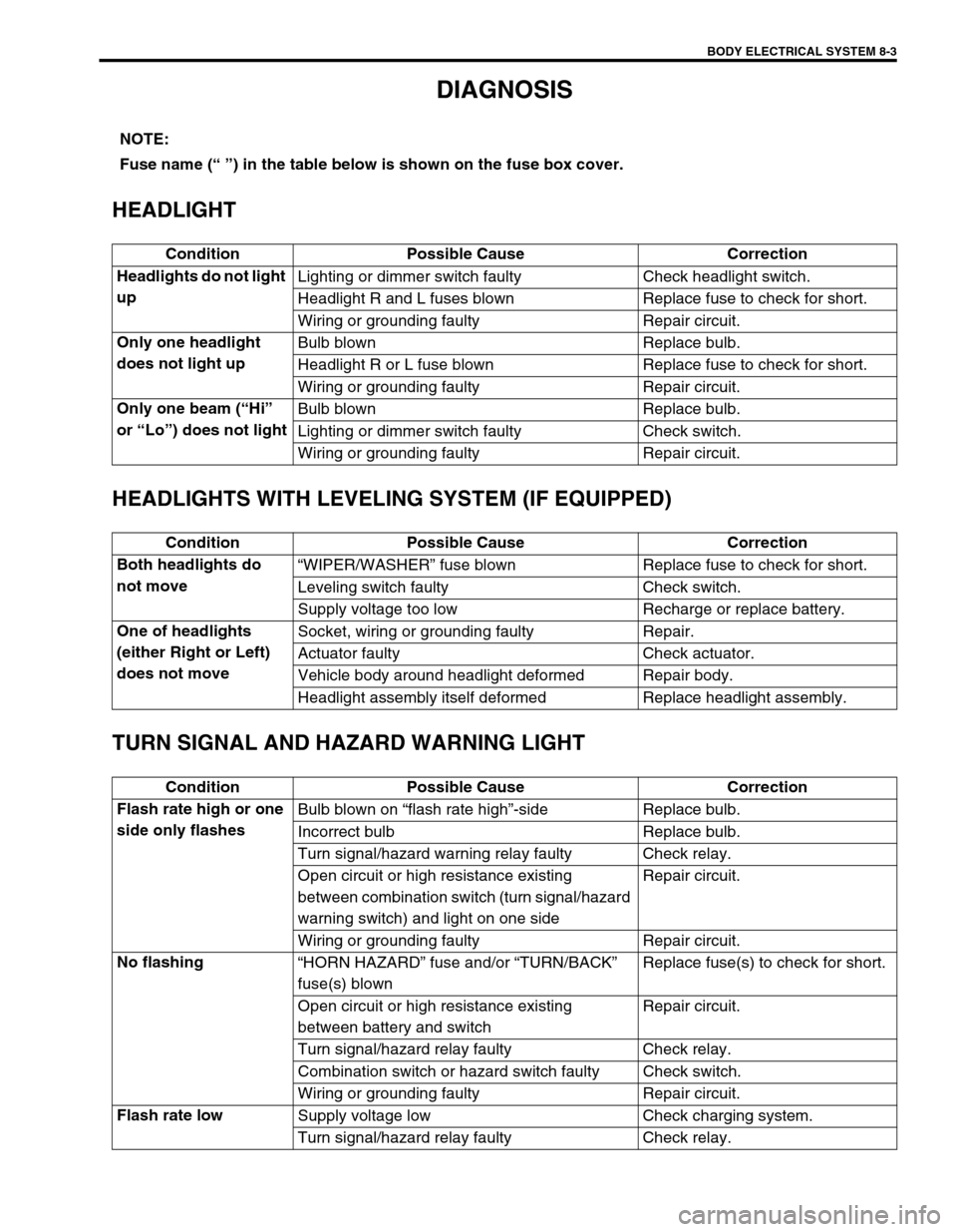
DIAGNOSIS
HEADLIGHT
HEADLIGHTS WITH LEVELING SYSTEM (IF EQUIPPED)
TURN SIGNAL AND HAZARD WARNING LIGHT
NOTE:
Fuse name (“ ”) in the table below is shown on the fuse box cover.
Condition Possible Cause Correction
Headlights do not light
upLighting or dimmer switch faulty Check headlight switch.
Headlight R and L fuses blown Replace fuse to check for short.
Wiring or grounding faulty Repair circuit.
Only one headlight
does not light upBulb blown Replace bulb.
Headlight R or L fuse blown Replace fuse to check for short.
Wiring or grounding faulty Repair circuit.
Only one beam (“Hi”
or “Lo”) does not lightBulb blown Replace bulb.
Lighting or dimmer switch faulty Check switch.
Wiring or grounding faulty Repair circuit.
Condition Possible Cause Correction
Both headlights do
not move“WIPER/WASHER” fuse blown Replace fuse to check for short.
Leveling switch faulty Check switch.
Supply voltage too low Recharge or replace battery.
One of headlights
(either Right or Left)
does not moveSocket, wiring or grounding faulty Repair.
Actuator faulty Check actuator.
Vehicle body around headlight deformed Repair body.
Headlight assembly itself deformed Replace headlight assembly.
Condition Possible Cause Correction
Flash rate high or one
side only flashesBulb blown on “flash rate high”-side Replace bulb.
Incorrect bulb Replace bulb.
Turn signal/hazard warning relay faulty Check relay.
Open circuit or high resistance existing
between combination switch (turn signal/hazard
warning switch) and light on one sideRepair circuit.
Wiring or grounding faulty Repair circuit.
No flashing
“HORN HAZARD” fuse and/or “TURN/BACK”
fuse(s) blownReplace fuse(s) to check for short.
Open circuit or high resistance existing
between battery and switchRepair circuit.
Turn signal/hazard relay faulty Check relay.
Combination switch or hazard switch faulty Check switch.
Wiring or grounding faulty Repair circuit.
Flash rate low
Supply voltage low Check charging system.
Turn signal/hazard relay faulty Check relay.
Page 248 of 447
8-4 BODY ELECTRICAL SYSTEM
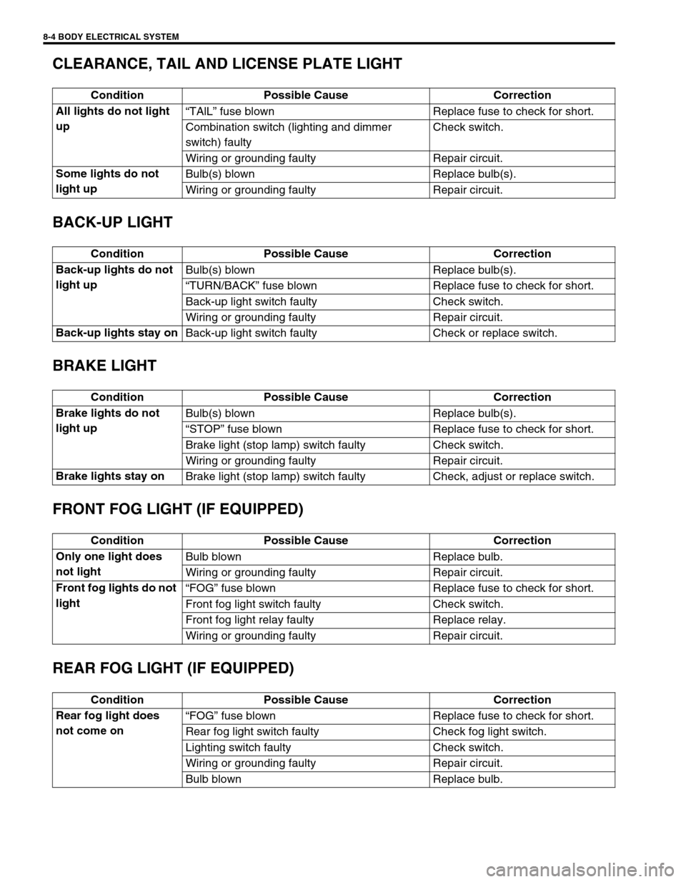
CLEARANCE, TAIL AND LICENSE PLATE LIGHT
BACK-UP LIGHT
BRAKE LIGHT
FRONT FOG LIGHT (IF EQUIPPED)
REAR FOG LIGHT (IF EQUIPPED)
Condition Possible Cause Correction
All lights do not light
up“TAlL” fuse blown Replace fuse to check for short.
Combination switch (lighting and dimmer
switch) faultyCheck switch.
Wiring or grounding faulty Repair circuit.
Some lights do not
light upBulb(s) blown Replace bulb(s).
Wiring or grounding faulty Repair circuit.
Condition Possible Cause Correction
Back-up lights do not
light upBulb(s) blown Replace bulb(s).
“TURN/BACK” fuse blown Replace fuse to check for short.
Back-up light switch faulty Check switch.
Wiring or grounding faulty Repair circuit.
Back-up lights stay on
Back-up light switch faulty Check or replace switch.
Condition Possible Cause Correction
Brake lights do not
light upBulb(s) blown Replace bulb(s).
“STOP” fuse blown Replace fuse to check for short.
Brake light (stop lamp) switch faulty Check switch.
Wiring or grounding faulty Repair circuit.
Brake lights stay on
Brake light (stop lamp) switch faulty Check, adjust or replace switch.
Condition Possible Cause Correction
Only one light does
not lightBulb blown Replace bulb.
Wiring or grounding faulty Repair circuit.
Front fog lights do not
light“FOG” fuse blown Replace fuse to check for short.
Front fog light switch faulty Check switch.
Front fog light relay faulty Replace relay.
Wiring or grounding faulty Repair circuit.
Condition Possible Cause Correction
Rear fog light does
not come on“FOG” fuse blown Replace fuse to check for short.
Rear fog light switch faulty Check fog light switch.
Lighting switch faulty Check switch.
Wiring or grounding faulty Repair circuit.
Bulb blown Replace bulb.
Page 249 of 447
BODY ELECTRICAL SYSTEM 8-5
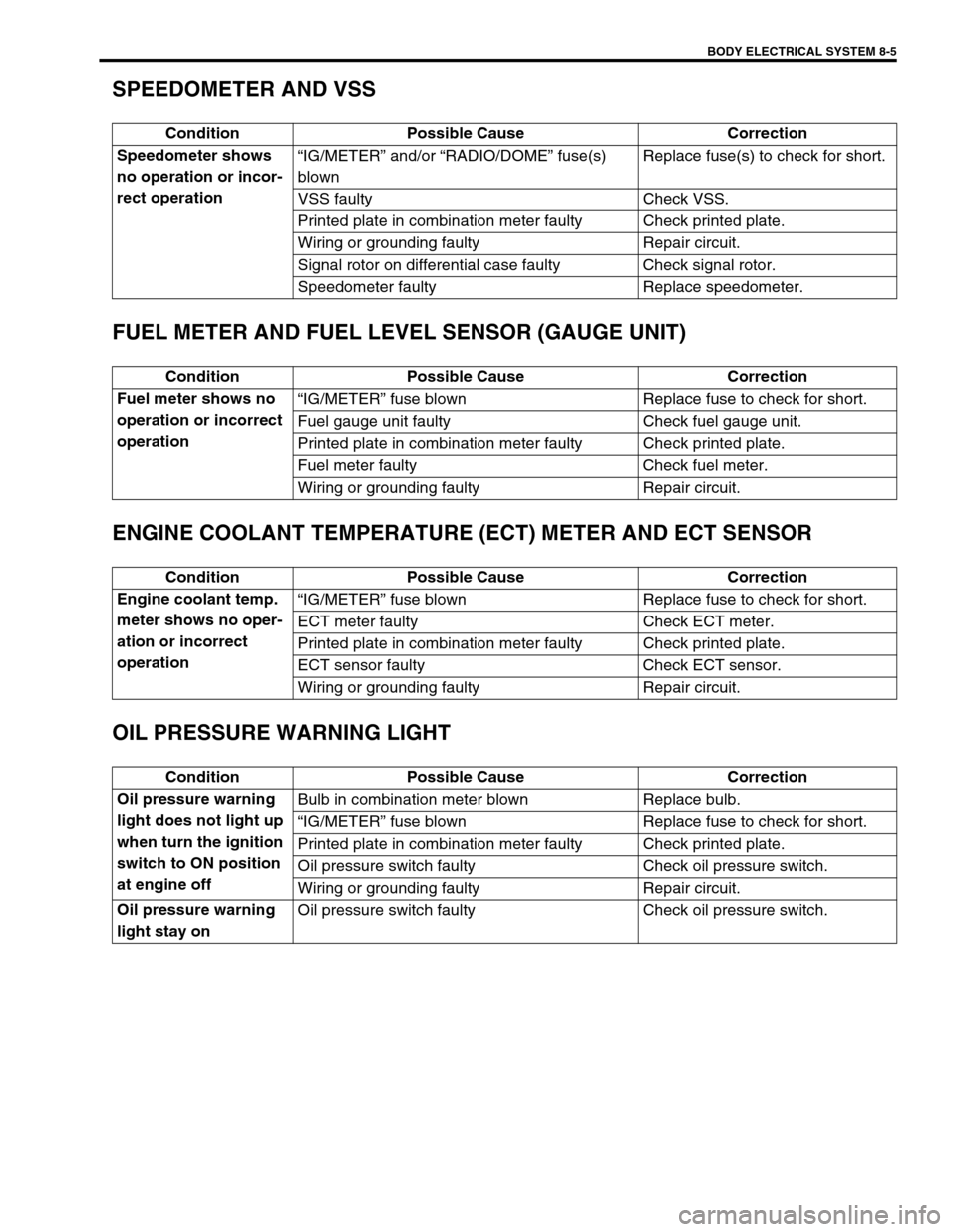
SPEEDOMETER AND VSS
FUEL METER AND FUEL LEVEL SENSOR (GAUGE UNIT)
ENGINE COOLANT TEMPERATURE (ECT) METER AND ECT SENSOR
OIL PRESSURE WARNING LIGHT
Condition Possible Cause Correction
Speedometer shows
no operation or incor-
rect operation“IG/METER” and/or “RADIO/DOME” fuse(s)
blownReplace fuse(s) to check for short.
VSS faulty Check VSS.
Printed plate in combination meter faulty Check printed plate.
Wiring or grounding faulty Repair circuit.
Signal rotor on differential case faulty Check signal rotor.
Speedometer faulty Replace speedometer.
Condition Possible Cause Correction
Fuel meter shows no
operation or incorrect
operation“IG/METER” fuse blown Replace fuse to check for short.
Fuel gauge unit faulty Check fuel gauge unit.
Printed plate in combination meter faulty Check printed plate.
Fuel meter faulty Check fuel meter.
Wiring or grounding faulty Repair circuit.
Condition Possible Cause Correction
Engine coolant temp.
meter shows no oper-
ation or incorrect
operation“IG/METER” fuse blown Replace fuse to check for short.
ECT meter faulty Check ECT meter.
Printed plate in combination meter faulty Check printed plate.
ECT sensor faulty Check ECT sensor.
Wiring or grounding faulty Repair circuit.
Condition Possible Cause Correction
Oil pressure warning
light does not light up
when turn the ignition
switch to ON position
at engine offBulb in combination meter blown Replace bulb.
“IG/METER” fuse blown Replace fuse to check for short.
Printed plate in combination meter faulty Check printed plate.
Oil pressure switch faulty Check oil pressure switch.
Wiring or grounding faulty Repair circuit.
Oil pressure warning
light stay onOil pressure switch faulty Check oil pressure switch.
Page 250 of 447
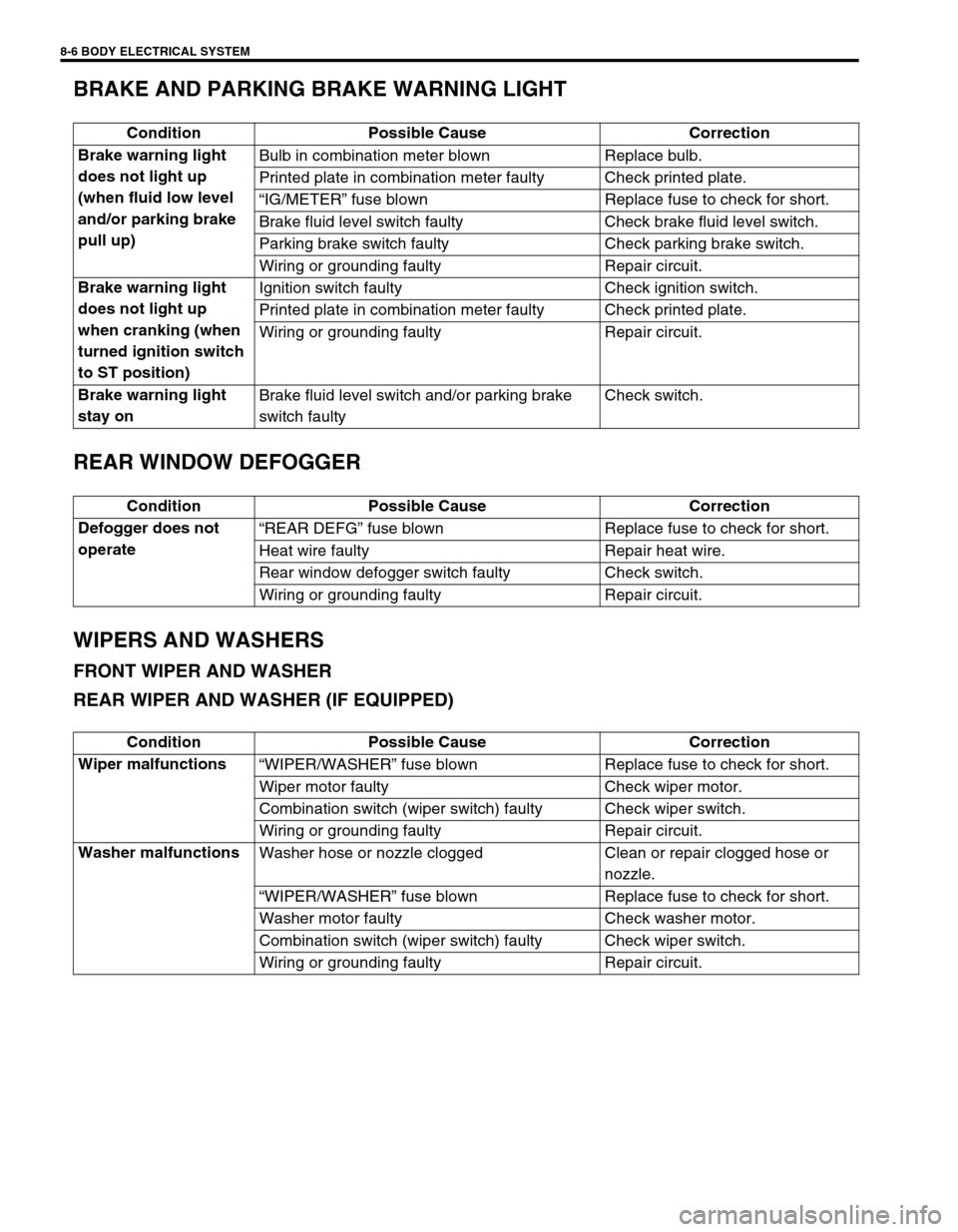
8-6 BODY ELECTRICAL SYSTEM
BRAKE AND PARKING BRAKE WARNING LIGHT
REAR WINDOW DEFOGGER
WIPERS AND WASHERS
FRONT WIPER AND WASHER
REAR WIPER AND WASHER (IF EQUIPPED)
Condition Possible Cause Correction
Brake warning light
does not light up
(when fluid low level
and/or parking brake
pull up)Bulb in combination meter blown Replace bulb.
Printed plate in combination meter faulty Check printed plate.
“IG/METER” fuse blown Replace fuse to check for short.
Brake fluid level switch faulty Check brake fluid level switch.
Parking brake switch faulty Check parking brake switch.
Wiring or grounding faulty Repair circuit.
Brake warning light
does not light up
when cranking (when
turned ignition switch
to ST position)Ignition switch faulty Check ignition switch.
Printed plate in combination meter faulty Check printed plate.
Wiring or grounding faulty Repair circuit.
Brake warning light
stay onBrake fluid level switch and/or parking brake
switch faultyCheck switch.
Condition Possible Cause Correction
Defogger does not
operate“REAR DEFG” fuse blown Replace fuse to check for short.
Heat wire faulty Repair heat wire.
Rear window defogger switch faulty Check switch.
Wiring or grounding faulty Repair circuit.
Condition Possible Cause Correction
Wiper malfunctions
“WIPER/WASHER” fuse blown Replace fuse to check for short.
Wiper motor faulty Check wiper motor.
Combination switch (wiper switch) faulty Check wiper switch.
Wiring or grounding faulty Repair circuit.
Washer malfunctions
Washer hose or nozzle clogged Clean or repair clogged hose or
nozzle.
“WIPER/WASHER” fuse blown Replace fuse to check for short.
Washer motor faulty Check washer motor.
Combination switch (wiper switch) faulty Check wiper switch.
Wiring or grounding faulty Repair circuit.
Page 252 of 447
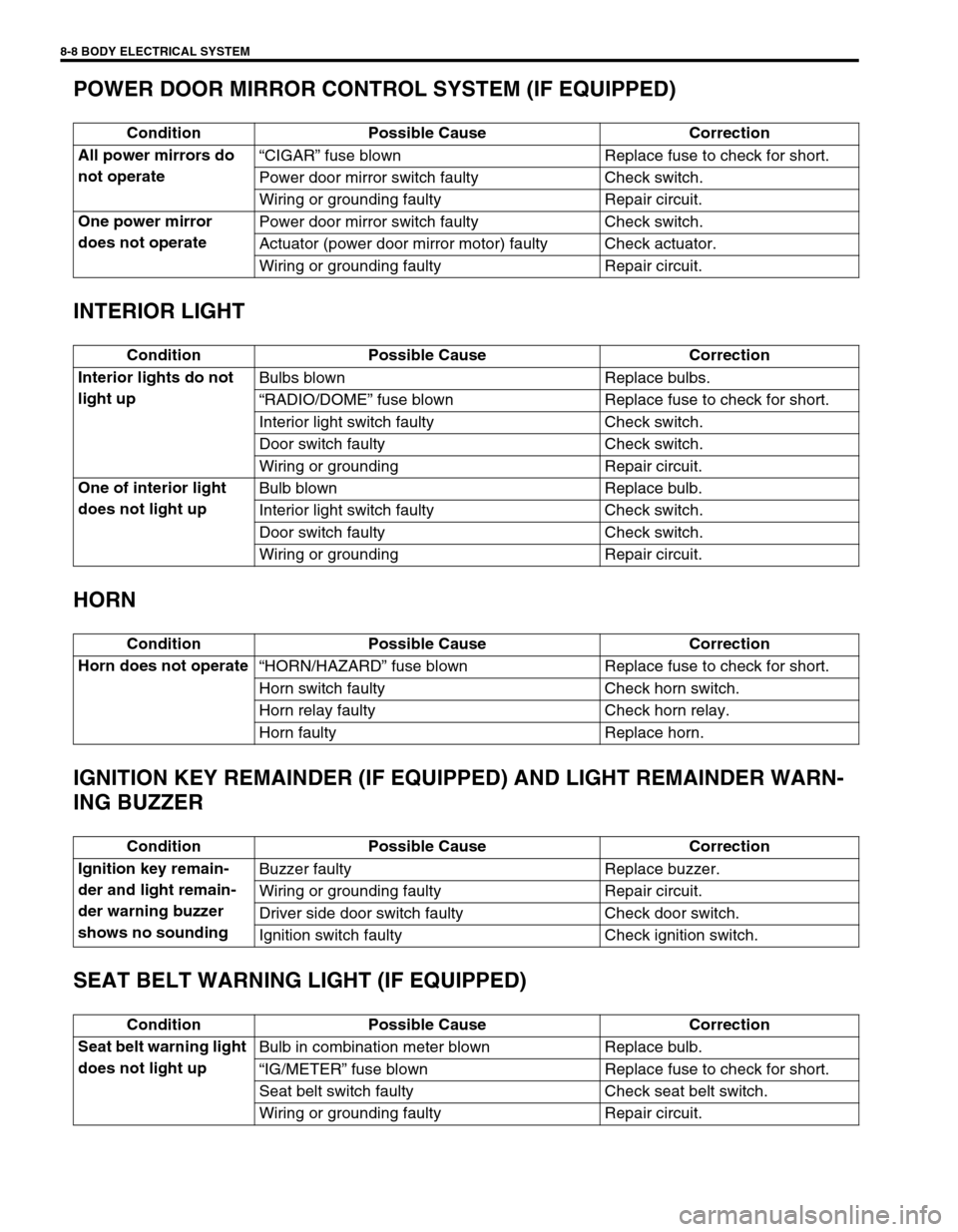
8-8 BODY ELECTRICAL SYSTEM
POWER DOOR MIRROR CONTROL SYSTEM (IF EQUIPPED)
INTERIOR LIGHT
HORN
IGNITION KEY REMAINDER (IF EQUIPPED) AND LIGHT REMAINDER WARN-
ING BUZZER
SEAT BELT WARNING LIGHT (IF EQUIPPED)
Condition Possible Cause Correction
All power mirrors do
not operate“CIGAR” fuse blown Replace fuse to check for short.
Power door mirror switch faulty Check switch.
Wiring or grounding faulty Repair circuit.
One power mirror
does not operatePower door mirror switch faulty Check switch.
Actuator (power door mirror motor) faulty Check actuator.
Wiring or grounding faulty Repair circuit.
Condition Possible Cause Correction
Interior lights do not
light upBulbs blown Replace bulbs.
“RADIO/DOME” fuse blown Replace fuse to check for short.
Interior light switch faulty Check switch.
Door switch faulty Check switch.
Wiring or grounding Repair circuit.
One of interior light
does not light upBulb blown Replace bulb.
Interior light switch faulty Check switch.
Door switch faulty Check switch.
Wiring or grounding Repair circuit.
Condition Possible Cause Correction
Horn does not operate
“HORN/HAZARD” fuse blown Replace fuse to check for short.
Horn switch faulty Check horn switch.
Horn relay faulty Check horn relay.
Horn faulty Replace horn.
Condition Possible Cause Correction
Ignition key remain-
der and light remain-
der warning buzzer
shows no soundingBuzzer faulty Replace buzzer.
Wiring or grounding faulty Repair circuit.
Driver side door switch faulty Check door switch.
Ignition switch faulty Check ignition switch.
Condition Possible Cause Correction
Seat belt warning light
does not light upBulb in combination meter blown Replace bulb.
“IG/METER” fuse blown Replace fuse to check for short.
Seat belt switch faulty Check seat belt switch.
Wiring or grounding faulty Repair circuit.
Page 254 of 447
8-10 BODY ELECTRICAL SYSTEM
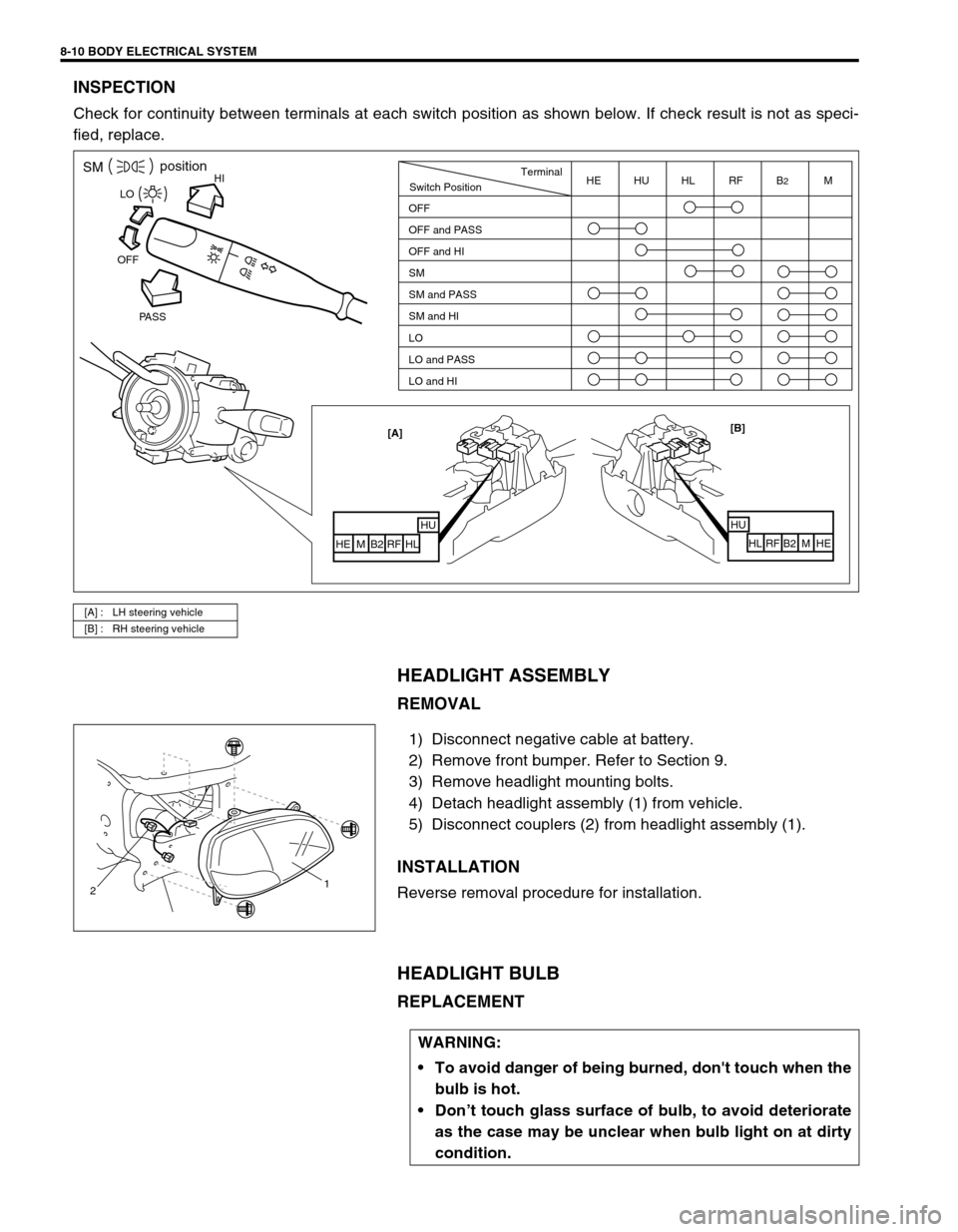
INSPECTION
Check for continuity between terminals at each switch position as shown below. If check result is not as speci-
fied, replace.
HEADLIGHT ASSEMBLY
REMOVAL
1) Disconnect negative cable at battery.
2) Remove front bumper. Refer to Section 9.
3) Remove headlight mounting bolts.
4) Detach headlight assembly (1) from vehicle.
5) Disconnect couplers (2) from headlight assembly (1).
INSTALLATION
Reverse removal procedure for installation.
HEADLIGHT BULB
REPLACEMENT
[A] : LH steering vehicle
[B] : RH steering vehicle
HISMposition
PASS OFFLO
[B]
HU
HL RF B2 M HE [A]
HUHL
RF B2 M HE
Switch PositionTerminal
OFF
OFF and PASS
OFF and HI
SM
SM and PASS
SM and HI
LO
LO and PASS
LO and HIHE HU HL RF B2M
21
WARNING:
To avoid danger of being burned, don't touch when the
bulb is hot.
Don’t touch glass surface of bulb, to avoid deteriorate
as the case may be unclear when bulb light on at dirty
condition.
Page 255 of 447
BODY ELECTRICAL SYSTEM 8-11
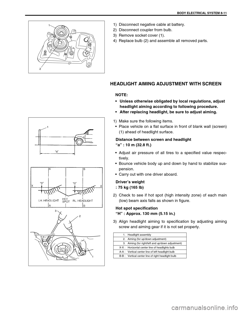
1) Disconnect negative cable at battery.
2) Disconnect coupler from bulb.
3) Remove socket cover (1).
4) Replace bulb (2) and assemble all removed parts.
HEADLIGHT AIMING ADJUSTMENT WITH SCREEN
1) Make sure the following items.
Place vehicle on a flat surface in front of blank wall (screen)
(1) ahead of headlight surface.
Distance between screen and headlight
“a” : 10 m (32.8 ft.)
Adjust air pressure of all tires to a specified value respec-
tively.
Bounce vehicle body up and down by hand to stabilize sus-
pension.
Carry out with one driver aboard.
Driver’s weight
: 75 kg (165 lb)
2) Check to see if hot spot (high intensity zone) of each main
(low) beam axis falls as shown in figure.
Hot spot specification
“H” : Approx. 130 mm (5.15 in.)
3) Align headlight aiming to specification by adjusting aiming
screw and aiming gear if it is not set properly.
21
NOTE:
Unless otherwise obligated by local regulations, adjust
headlight aiming according to following procedure.
After replacing headlight, be sure to adjust aiming.
1. Headlight assembly
2. Aiming (for up/down adjustment)
3. Aiming (for right/left and up/down adjustment)
X-X : Horizontal center line of headlights bulb
A-A : Vertical center line of left headlight bulb
B-B : Vertical center line of right headlight bulb
1 2 3
Page 257 of 447
BODY ELECTRICAL SYSTEM 8-13
TURN SIGNAL AND HAZARD RELAY
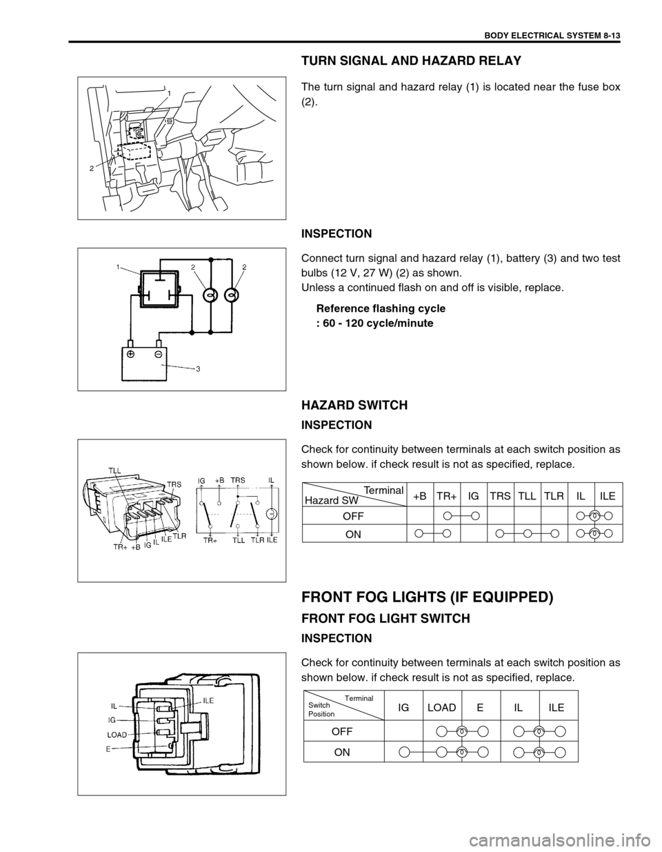
The turn signal and hazard relay (1) is located near the fuse box
(2).
INSPECTION
Connect turn signal and hazard relay (1), battery (3) and two test
bulbs (12 V, 27 W) (2) as shown.
Unless a continued flash on and off is visible, replace.
Reference flashing cycle
: 60 - 120 cycle/minute
HAZARD SWITCH
INSPECTION
Check for continuity between terminals at each switch position as
shown below. if check result is not as specified, replace.
FRONT FOG LIGHTS (IF EQUIPPED)
FRONT FOG LIGHT SWITCH
INSPECTION
Check for continuity between terminals at each switch position as
shown below. if check result is not as specified, replace.
1
2
Hazard SWTerminal
OFF
ON+B TR+ IG TRS TLL TLR IL ILE
Switch
PositionTerminal
ONIG LOAD E IL ILE
OFF
Page 260 of 447
8-16 BODY ELECTRICAL SYSTEM
REMOVAL
1) Disconnect negative cable at battery.
2) Loosen steering column mounting nuts. Refer to Section 3C.
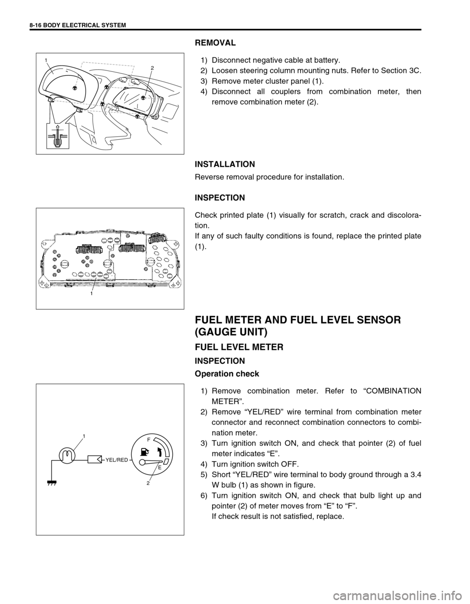
3) Remove meter cluster panel (1).
4) Disconnect all couplers from combination meter, then
remove combination meter (2).
INSTALLATION
Reverse removal procedure for installation.
INSPECTION
Check printed plate (1) visually for scratch, crack and discolora-
tion.
If any of such faulty conditions is found, replace the printed plate
(1).
FUEL METER AND FUEL LEVEL SENSOR
(GAUGE UNIT)
FUEL LEVEL METER
INSPECTION
Operation check
1) Remove combination meter. Refer to “COMBINATION
METER”.
2) Remove “YEL/RED” wire terminal from combination meter
connector and reconnect combination connectors to combi-
nation meter.
3) Turn ignition switch ON, and check that pointer (2) of fuel
meter indicates “E”.
4) Turn ignition switch OFF.
5) Short “YEL/RED” wire terminal to body ground through a 3.4
W bulb (1) as shown in figure.
6) Turn ignition switch ON, and check that bulb light up and
pointer (2) of meter moves from “E” to “F”.
If check result is not satisfied, replace.
1
2
YEL/REDF
E
2 1