tow SUZUKI SWIFT 2000 1.G Transmission Service Workshop Manual
[x] Cancel search | Manufacturer: SUZUKI, Model Year: 2000, Model line: SWIFT, Model: SUZUKI SWIFT 2000 1.GPages: 447, PDF Size: 10.54 MB
Page 30 of 447
7A-30 MANUAL TRANSMISSION
2) Insert each gear shift shaft into case and check that it moves
smoothly. If it doesn’t, correct by using oilstone, reamer or
the like.
5th & Reverse Gear Shifter
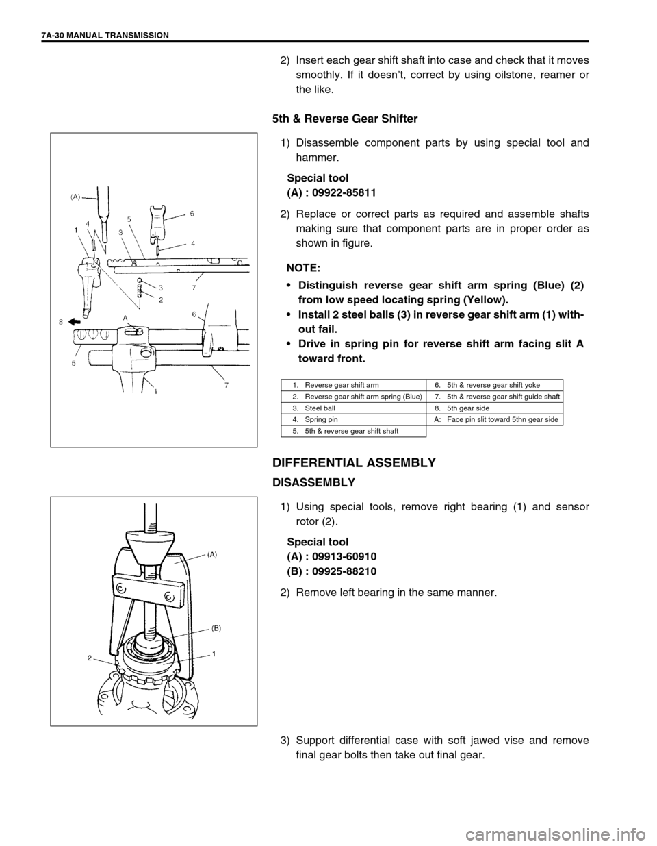
1) Disassemble component parts by using special tool and
hammer.
Special tool
(A) : 09922-85811
2) Replace or correct parts as required and assemble shafts
making sure that component parts are in proper order as
shown in figure.
DIFFERENTIAL ASSEMBLY
DISASSEMBLY
1) Using special tools, remove right bearing (1) and sensor
rotor (2).
Special tool
(A) : 09913-60910
(B) : 09925-88210
2) Remove left bearing in the same manner.
3) Support differential case with soft jawed vise and remove
final gear bolts then take out final gear. NOTE:
Distinguish reverse gear shift arm spring (Blue) (2)
from low speed locating spring (Yellow).
Install 2 steel balls (3) in reverse gear shift arm (1) with-
out fail.
Drive in spring pin for reverse shift arm facing slit A
toward front.
1. Reverse gear shift arm 6. 5th & reverse gear shift yoke
2. Reverse gear shift arm spring (Blue) 7. 5th & reverse gear shift guide shaft
3. Steel ball 8. 5th gear side
4. Spring pin A: Face pin slit toward 5thn gear side
5. 5th & reverse gear shift shaft
Page 275 of 447
BODY ELECTRICAL SYSTEM 8-31
CODE REGISTRATION PROCEDURE
1) Confirm that IG switch is OFF position.
2) Remove DOOR LOCK fuse and install it again.
3) Press the button on the transmitter one time toward the
receiver within 30 seconds.
4) If two transmitters are registered, repeat step 1) to 3) with
other transmitter.
POWER DOOR MIRROR CONTROL SYSTEM
(IF EQUIPPED)
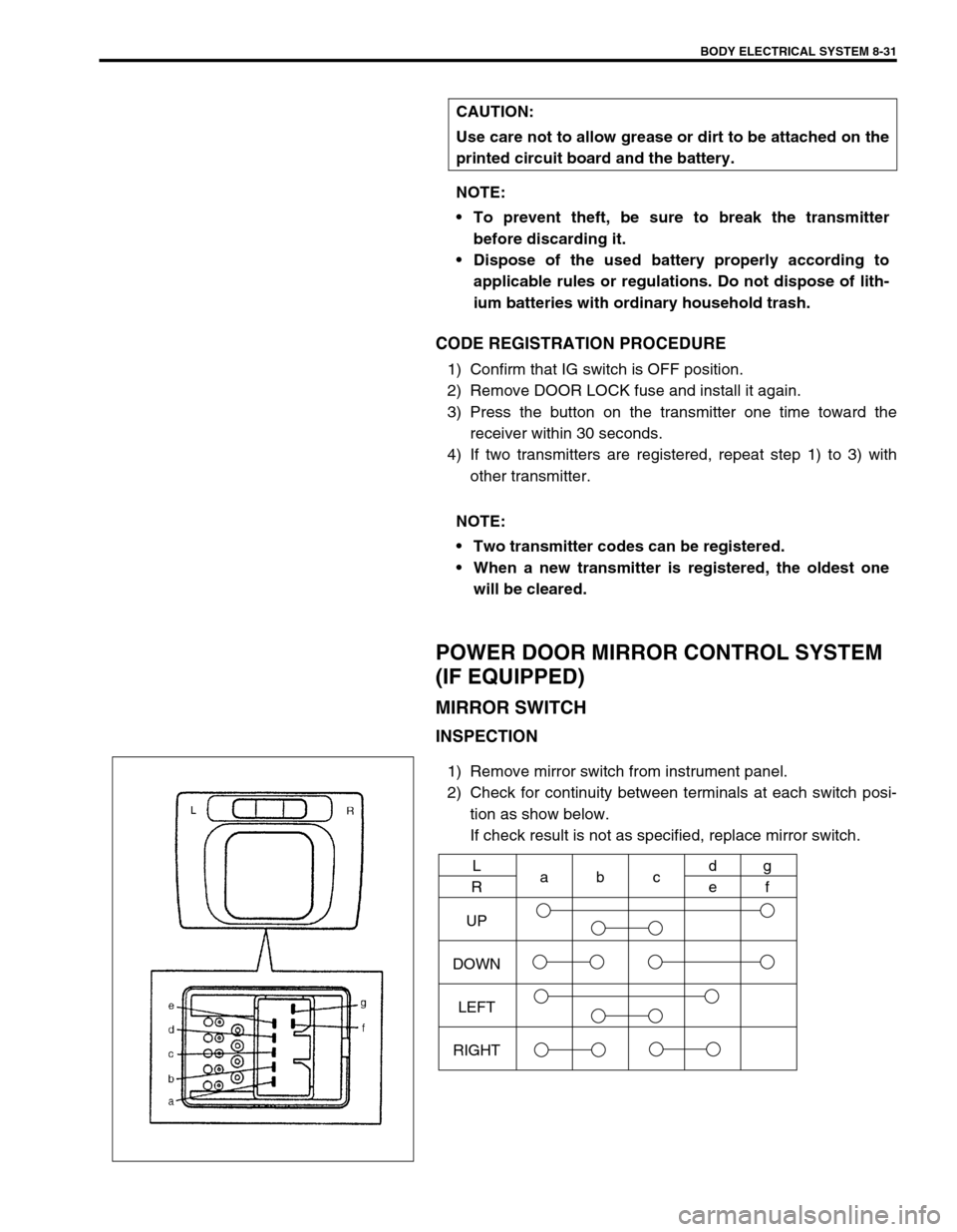
MIRROR SWITCH
INSPECTION
1) Remove mirror switch from instrument panel.
2) Check for continuity between terminals at each switch posi-
tion as show below.
If check result is not as specified, replace mirror switch. CAUTION:
Use care not to allow grease or dirt to be attached on the
printed circuit board and the battery.
NOTE:
To prevent theft, be sure to break the transmitter
before discarding it.
Dispose of the used battery properly according to
applicable rules or regulations. Do not dispose of lith-
ium batteries with ordinary household trash.
NOTE:
Two transmitter codes can be registered.
When a new transmitter is registered, the oldest one
will be cleared.
UP
DOWN
LEFT
RIGHTL
Rabcd
eg
f
Page 372 of 447
10-6 RESTRAINT SYSTEM
REMOVAL
1) Disconnect negative battery cable at battery.
2) Disable air bag system. Refer to “DISABLING AIR BAG SYSTEM” of “SERVICE PRECAUTIONS” under
“ON-VEHICLE SERVICE” in Section 10B.
3) Remove center pillar lower trim.
4) Disconnect Yellow connector for seat belt pretensioner.
a) Release locking of lock lever.
b) After unlocked, disconnect to connector.
5) Remove front seat belts from the vehicle.
INSPECTION
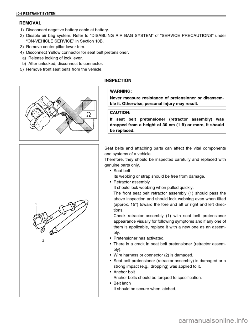
Seat belts and attaching parts can affect the vital components
and systems of a vehicle.
Therefore, they should be inspected carefully and replaced with
genuine parts only.
Seat belt
Its webbing or strap should be free from damage.
Retractor assembly
It should lock webbing when pulled quickly.
The front seat belt retractor assembly (1) should pass the
above inspection and should lock webbing even when tilted
(approx. 15°) toward the fore and aft or right and left direc-
tions.
Check retractor assembly (1) with seat belt pretensioner
appearance visually for following symptoms and if any one of
them is applicable, replace it with a new one as an assem-
bly.
Pretensioner has activated.
There is a crack in seat belt pretensioner (retractor assem-
bly).
Wire harness or connector (2) is damaged.
Seat belt pretensioner (retractor assembly) is damaged or a
strong impact (e.g., dropping) was applied to it.
Anchor bolt
Anchor bolts should be torqued to specification.
Belt latch
It should be secure when latched. WARNING:
Never measure resistance of pretensioner or disassem-
ble it. Otherwise, personal injury may result.
CAUTION:
If seat belt pretensioner (retractor assembly) was
dropped from a height of 30 cm (1 ft) or more, it should
be replaced.
Page 422 of 447
10B-48 AIR BAG SYSTEM
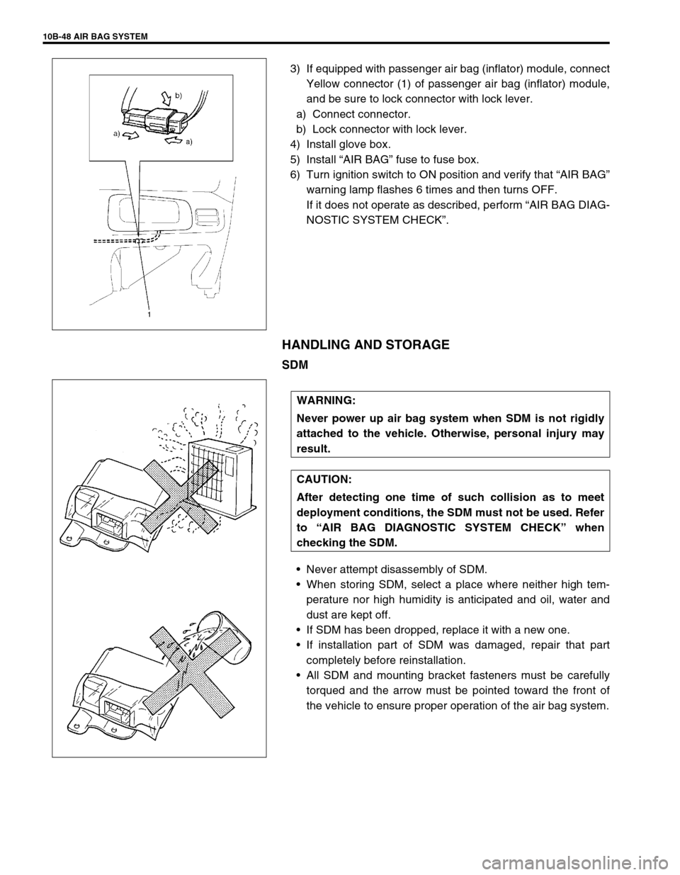
3) If equipped with passenger air bag (inflator) module, connect
Yellow connector (1) of passenger air bag (inflator) module,
and be sure to lock connector with lock lever.
a) Connect connector.
b) Lock connector with lock lever.
4) Install glove box.
5) Install “AIR BAG” fuse to fuse box.
6) Turn ignition switch to ON position and verify that “AIR BAG”
warning lamp flashes 6 times and then turns OFF.
If it does not operate as described, perform “AIR BAG DIAG-
NOSTIC SYSTEM CHECK”.
HANDLING AND STORAGE
SDM
Never attempt disassembly of SDM.
When storing SDM, select a place where neither high tem-
perature nor high humidity is anticipated and oil, water and
dust are kept off.
If SDM has been dropped, replace it with a new one.
If installation part of SDM was damaged, repair that part
completely before reinstallation.
All SDM and mounting bracket fasteners must be carefully
torqued and the arrow must be pointed toward the front of
the vehicle to ensure proper operation of the air bag system.
WARNING:
Never power up air bag system when SDM is not rigidly
attached to the vehicle. Otherwise, personal injury may
result.
CAUTION:
After detecting one time of such collision as to meet
deployment conditions, the SDM must not be used. Refer
to “AIR BAG DIAGNOSTIC SYSTEM CHECK” when
checking the SDM.
Page 431 of 447
AIR BAG SYSTEM 10B-57
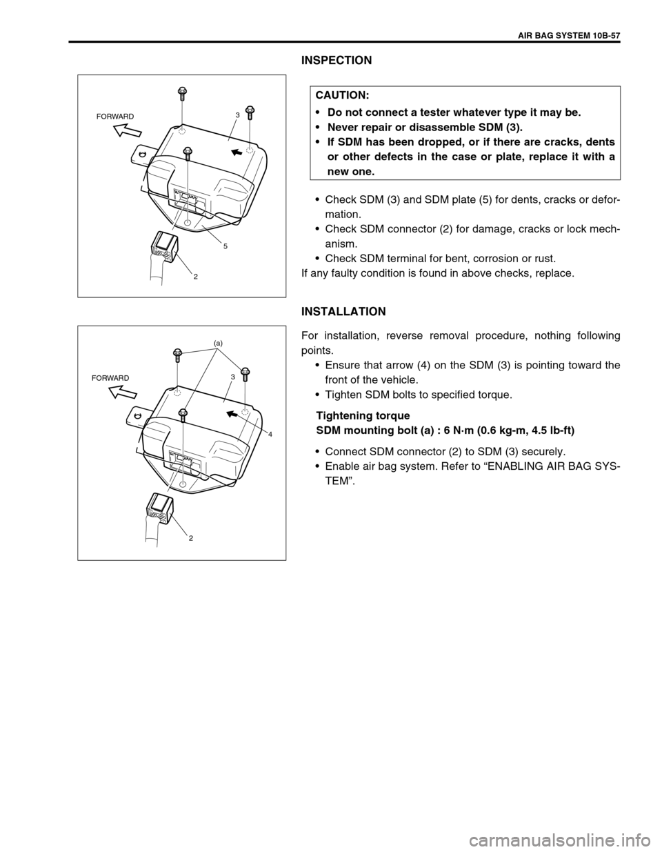
INSPECTION
Check SDM (3) and SDM plate (5) for dents, cracks or defor-
mation.
Check SDM connector (2) for damage, cracks or lock mech-
anism.
Check SDM terminal for bent, corrosion or rust.
If any faulty condition is found in above checks, replace.
INSTALLATION
For installation, reverse removal procedure, nothing following
points.
Ensure that arrow (4) on the SDM (3) is pointing toward the
front of the vehicle.
Tighten SDM bolts to specified torque.
Tightening torque
SDM mounting bolt (a) : 6 N·m (0.6 kg-m, 4.5 lb-ft)
Connect SDM connector (2) to SDM (3) securely.
Enable air bag system. Refer to “ENABLING AIR BAG SYS-
TEM”. CAUTION:
Do not connect a tester whatever type it may be.
Never repair or disassemble SDM (3).
If SDM has been dropped, or if there are cracks, dents
or other defects in the case or plate, replace it with a
new one.
3
5
2 FORWARD
(a)
3
4
2 FORWARD