turn signal SUZUKI SWIFT 2000 1.G Transmission Service Workshop Manual
[x] Cancel search | Manufacturer: SUZUKI, Model Year: 2000, Model line: SWIFT, Model: SUZUKI SWIFT 2000 1.GPages: 447, PDF Size: 10.54 MB
Page 43 of 447
AUTOMATIC TRANSMISSION (4 A/T) 7B-1
6F1
6F2
6G
6H
6K
7A
7A1
7C1
7D
7B
7F
8A
8B
8C
8D
8E
9
10
10A
10B
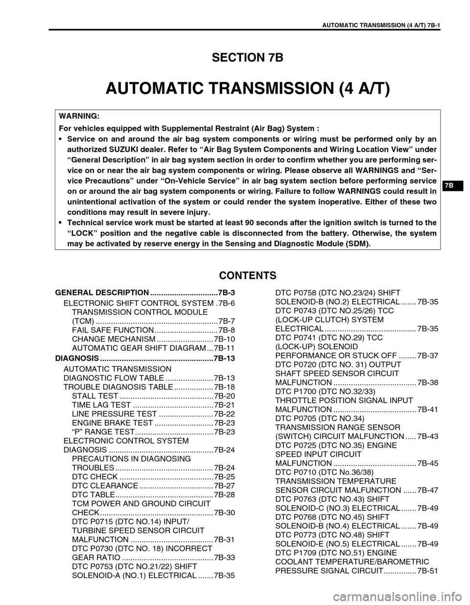
SECTION 7B
AUTOMATIC TRANSMISSION (4 A/T)
CONTENTS
GENERAL DESCRIPTION ...............................7B-3
ELECTRONIC SHIFT CONTROL SYSTEM . 7B-6
TRANSMISSION CONTROL MODULE
(TCM) ........................................................ 7B-7
FAIL SAFE FUNCTION ............................. 7B-8
CHANGE MECHANISM .......................... 7B-10
AUTOMATIC GEAR SHIFT DIAGRAM ... 7B-11
DIAGNOSIS ....................................................7B-13
AUTOMATIC TRANSMISSION
DIAGNOSTIC FLOW TABLE ...................... 7B-13
TROUBLE DIAGNOSIS TABLE .................. 7B-18
STALL TEST ........................................... 7B-20
TIME LAG TEST ..................................... 7B-21
LINE PRESSURE TEST ......................... 7B-22
ENGINE BRAKE TEST ........................... 7B-23
“P” RANGE TEST.................................... 7B-23
ELECTRONIC CONTROL SYSTEM
DIAGNOSIS ................................................ 7B-24
PRECAUTIONS IN DIAGNOSING
TROUBLES ............................................. 7B-24
DTC CHECK ........................................... 7B-25
DTC CLEARANCE .................................. 7B-27
DTC TABLE............................................. 7B-28
TCM POWER AND GROUND CIRCUIT
CHECK .................................................... 7B-30
DTC P0715 (DTC NO.14) INPUT/
TURBINE SPEED SENSOR CIRCUIT
MALFUNCTION ...................................... 7B-31
DTC P0730 (DTC NO. 18) INCORRECT
GEAR RATIO .......................................... 7B-33
DTC P0753 (DTC NO.21/22) SHIFT
SOLENOID-A (NO.1) ELECTRICAL ....... 7B-35DTC P0758 (DTC NO.23/24) SHIFT
SOLENOID-B (NO.2) ELECTRICAL ....... 7B-35
DTC P0743 (DTC NO.25/26) TCC
(LOCK-UP CLUTCH) SYSTEM
ELECTRICAL .......................................... 7B-35
DTC P0741 (DTC NO.29) TCC
(LOCK-UP) SOLENOID
PERFORMANCE OR STUCK OFF ........ 7B-37
DTC P0720 (DTC NO. 31) OUTPUT
SHAFT SPEED SENSOR CIRCUIT
MALFUNCTION ...................................... 7B-38
DTC P1700 (DTC NO.32/33)
THROTTLE POSITION SIGNAL INPUT
MALFUNCTION ...................................... 7B-41
DTC P0705 (DTC NO.34)
TRANSMISSION RANGE SENSOR
(SWITCH) CIRCUIT MALFUNCTION ..... 7B-43
DTC P0725 (DTC NO.35) ENGINE
SPEED INPUT CIRCUIT
MALFUNCTION ...................................... 7B-45
DTC P0710 (DTC No.36/38)
TRANSMISSION TEMPERATURE
SENSOR CIRCUIT MALFUNCTION ...... 7B-47
DTC P0763 (DTC NO.43) SHIFT
SOLENOID-C (NO.3) ELECTRICAL ....... 7B-49
DTC P0768 (DTC NO.45) SHIFT
SOLENOID-B (NO.4) ELECTRICAL ....... 7B-49
DTC P0773 (DTC NO.48) SHIFT
SOLENOID-E (NO.5) ELECTRICAL ....... 7B-49
DTC P1709 (DTC NO.51) ENGINE
COOLANT TEMPERATURE/BAROMETRIC
PRESSURE SIGNAL CIRCUIT............... 7B-51 WARNING:
For vehicles equipped with Supplemental Restraint (Air Bag) System :
Service on and around the air bag system components or wiring must be performed only by an
authorized SUZUKI dealer. Refer to “Air Bag System Components and Wiring Location View” under
“General Description” in air bag system section in order to confirm whether you are performing ser-
vice on or near the air bag system components or wiring. Please observe all WARNINGS and “Ser-
vice Precautions” under “On-Vehicle Service” in air bag system section before performing service
on or around the air bag system components or wiring. Failure to follow WARNINGS could result in
unintentional activation of the system or could render the system inoperative. Either of these two
conditions may result in severe injury.
Technical service work must be started at least 90 seconds after the ignition switch is turned to the
“LOCK” position and the negative cable is disconnected from the battery. Otherwise, the system
may be activated by reserve energy in the Sensing and Diagnostic Module (SDM).
Page 50 of 447
7B-8 AUTOMATIC TRANSMISSION (4 A/T)
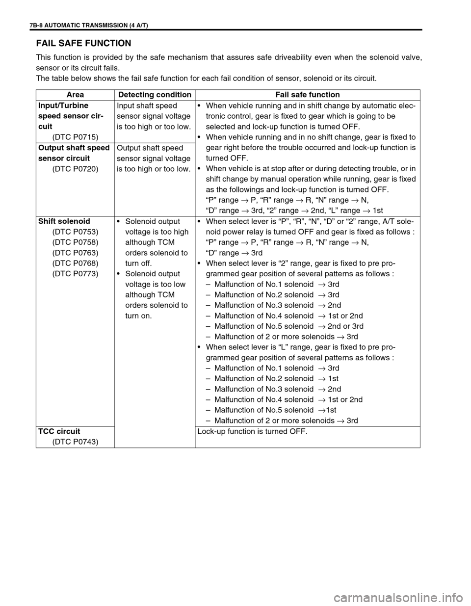
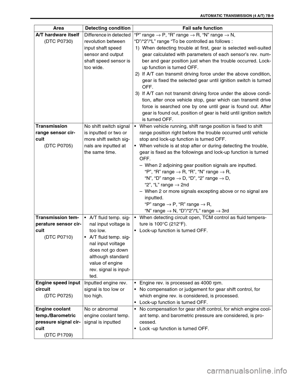
FAIL SAFE FUNCTION
This function is provided by the safe mechanism that assures safe driveability even when the solenoid valve,
sensor or its circuit fails.
The table below shows the fail safe function for each fail condition of sensor, solenoid or its circuit.
Area Detecting condition Fail safe function
Input/Turbine
speed sensor cir-
cuit
(DTC P0715)Input shaft speed
sensor signal voltage
is too high or too low.When vehicle running and in shift change by automatic elec-
tronic control, gear is fixed to gear which is going to be
selected and lock-up function is turned OFF.
When vehicle running and in no shift change, gear is fixed to
gear right before the trouble occurred and lock-up function is
turned OFF.
When vehicle is at stop after or during detecting trouble, or in
shift change by manual operation while running, gear is fixed
as the followings and lock-up function is turned OFF.
“P” range →
P, “R” range →
R, “N” range →
N,
“D” range →
3rd, “2” range →
2nd, “L” range →
1st Output shaft speed
sensor circuit
(DTC P0720)Output shaft speed
sensor signal voltage
is too high or too low.
Shift solenoid
(DTC P0753)
(DTC P0758)
(DTC P0763)
(DTC P0768)
(DTC P0773)Solenoid output
voltage is too high
although TCM
orders solenoid to
turn off.
Solenoid output
voltage is too low
although TCM
orders solenoid to
turn on.When select lever is “P”, “R”, “N”, “D” or “2” range, A/T sole-
noid power relay is turned OFF and gear is fixed as follows :
“P” range →
P, “R” range →
R, “N” range →
N,
“D” range →
3rd
When select lever is “2” range, gear is fixed to pre pro-
grammed gear position of several patterns as follows :
–Malfunction of No.1 solenoid →
3rd
–Malfunction of No.2 solenoid →
3rd
–Malfunction of No.3 solenoid →
2nd
–Malfunction of No.4 solenoid →
1st or 2nd
–Malfunction of No.5 solenoid →
2nd or 3rd
–Malfunction of 2 or more solenoids →
3rd
When select lever is “L” range, gear is fixed to pre pro-
grammed gear position of several patterns as follows :
–Malfunction of No.1 solenoid →
3rd
–Malfunction of No.2 solenoid →
1st
–Malfunction of No.3 solenoid →
2nd
–Malfunction of No.4 solenoid →
1st or 2nd
–Malfunction of No.5 solenoid →
1st
–Malfunction of 2 or more solenoids →
3rd
TCC circuit
(DTC P0743)Lock-up function is turned OFF.
Page 51 of 447
AUTOMATIC TRANSMISSION (4 A/T) 7B-9
A/T hardware itself
(DTC P0730)Difference in detected
revolution between
input shaft speed
sensor and output
shaft speed sensor is
too wide.“P” range →
P, “R” range →
R, “N” range →
N,
“D”/“2”/“L” range “To be controlled as follows :
1) When detecting trouble at first, gear is selected well-suited
gear calculated with parameters of each sensor’s rev. num-
ber and gear position just when the trouble occurred. Lock-
up function is turned OFF.
2) If A/T can transmit driving force under the above condition,
gear is fixed the selected gear until ignition switch is turned
OFF.
3) If A/T can not transmit driving force under the above condi-
tion, after once vehicle stop, gear which can transmit drive
force is searched one by one until gear is found out. After
gear is found out, position of gear is held until ignition switch
is turned OFF.
Transmission
range sensor cir-
cuit
(DTC P0705)No shift switch signal
is inputted or two or
more shift switch sig-
nals are inputted at
the same time.When vehicle running, shift range position is fixed to shift
range position right before the trouble occurred until vehicle
stop and lock-up function is turned OFF.
When vehicle is at stop after or during detecting the trouble,
gear is fixed as the followings and lock-up function is turned
OFF.
–When 2 adjoining gear position signals are inputted.
“P”, “R” range →
R, “R”, “N” range →
R,
“N”, “D” range →
D, “D”, “2” range →
D,
“2”, “L” range →
2nd
–When 2 or more signals excepting above or no signal are
inputted.
“P” range →
P, “R” range →
R,
“N” range →
N, “D”/“2”/“L” range →
3rd
Transmission tem-
perature sensor cir-
cuit
(DTC P0710)A/T fluid temp. sig-
nal input voltage is
too low.
A/T fluid temp. sig-
nal input voltage
does not go down
although standard
value of engine
rev. signal is input-
ted.When detecting circuit open, TCM control as fluid tempera-
ture is 100°C (212°F).
Lock-up function is turned OFF.
Engine speed input
circuit
(DTC P0725)Inputted engine rev.
signal is too low or
too high.Engine rev. is processed as 4000 rpm.
No compensation or judgement for gear shift control, for
which engine rev. is considered, is processed.
Lock-up function is turned OFF.
Engine coolant
temp./Barometric
pressure signal cir-
cuit
(DTC P1709)No or abnormal
engine coolant temp.
signal is inputtedNo compensation for gear shift control, for which engine cool-
ant temp. and barometric pressure are considered, is pro-
cessed.
Lock -up function is turned OFF. Area Detecting condition Fail safe function
Page 52 of 447
7B-10 AUTOMATIC TRANSMISSION (4 A/T)
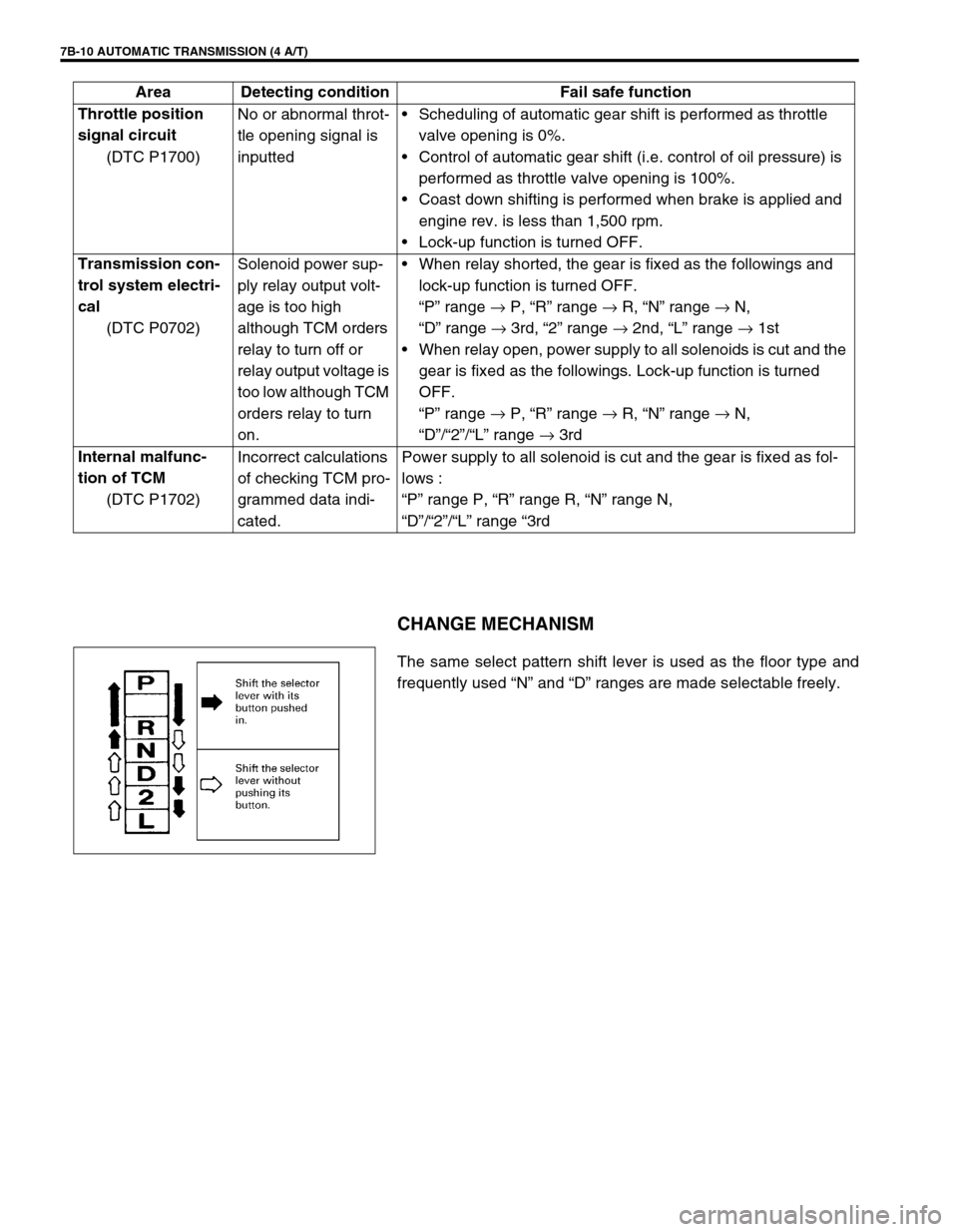
CHANGE MECHANISM
The same select pattern shift lever is used as the floor type and
frequently used “N” and “D” ranges are made selectable freely. Throttle position
signal circuit
(DTC P1700)No or abnormal throt-
tle opening signal is
inputtedScheduling of automatic gear shift is performed as throttle
valve opening is 0%.
Control of automatic gear shift (i.e. control of oil pressure) is
performed as throttle valve opening is 100%.
Coast down shifting is performed when brake is applied and
engine rev. is less than 1,500 rpm.
Lock-up function is turned OFF.
Transmission con-
trol system electri-
cal
(DTC P0702)Solenoid power sup-
ply relay output volt-
age is too high
although TCM orders
relay to turn off or
relay output voltage is
too low although TCM
orders relay to turn
on.When relay shorted, the gear is fixed as the followings and
lock-up function is turned OFF.
“P” range →
P, “R” range →
R, “N” range →
N,
“D” range →
3rd, “2” range →
2nd, “L” range →
1st
When relay open, power supply to all solenoids is cut and the
gear is fixed as the followings. Lock-up function is turned
OFF.
“P” range →
P, “R” range →
R, “N” range →
N,
“D”/“2”/“L” range →
3rd
Internal malfunc-
tion of TCM
(DTC P1702)Incorrect calculations
of checking TCM pro-
grammed data indi-
cated.Power supply to all solenoid is cut and the gear is fixed as fol-
lows :
“P” range P, “R” range R, “N” range N,
“D”/“2”/“L” range “3rd Area Detecting condition Fail safe function
Page 73 of 447
AUTOMATIC TRANSMISSION (4 A/T) 7B-31
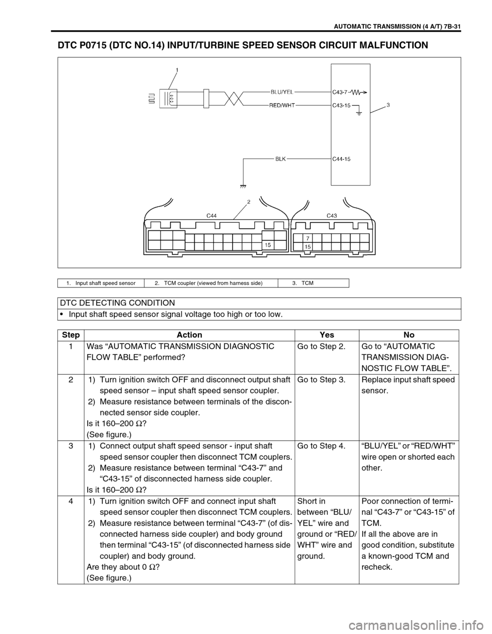
DTC P0715 (DTC NO.14) INPUT/TURBINE SPEED SENSOR CIRCUIT MALFUNCTION
1. Input shaft speed sensor 2. TCM coupler (viewed from harness side) 3. TCM
DTC DETECTING CONDITION
Input shaft speed sensor signal voltage too high or too low.
Step Action Yes No
1Was “AUTOMATIC TRANSMISSION DIAGNOSTIC
FLOW TABLE” performed?Go to Step 2. Go to “AUTOMATIC
TRANSMISSION DIAG-
NOSTIC FLOW TABLE”.
2 1) Turn ignition switch OFF and disconnect output shaft
speed sensor – input shaft speed sensor coupler.
2) Measure resistance between terminals of the discon-
nected sensor side coupler.
Is it 160–200 Ω
?
(See figure.)Go to Step 3. Replace input shaft speed
sensor.
3 1) Connect output shaft speed sensor - input shaft
speed sensor coupler then disconnect TCM couplers.
2) Measure resistance between terminal “C43-7” and
“C43-15” of disconnected harness side coupler.
Is it 160–200 Ω
?Go to Step 4.“BLU/YEL” or “RED/WHT”
wire open or shorted each
other.
4 1) Turn ignition switch OFF and connect input shaft
speed sensor coupler then disconnect TCM couplers.
2) Measure resistance between terminal “C43-7” (of dis-
connected harness side coupler) and body ground
then terminal “C43-15” (of disconnected harness side
coupler) and body ground.
Are they about 0 Ω
?
(See figure.)Short in
between “BLU/
YEL” wire and
ground or “RED/
WHT” wire and
ground.Poor connection of termi-
nal “C43-7” or “C43-15” of
TCM.
If all the above are in
good condition, substitute
a known-good TCM and
recheck.
Page 79 of 447
AUTOMATIC TRANSMISSION (4 A/T) 7B-37
DTC P0741 (DTC NO.29) TCC (LOCK-UP) SOLENOID PERFORMANCE OR STUCK OFF
Step Action Yes No
1Was “AUTOMATIC TRANSMISSION DIAG-
NOSTIC FLOW TABLE” performed?Go to Step 2. Go to “AUTOMATIC
TRANSMISSION DIAG-
NOSTIC FLOW TABLE”.
2 Check TCC (lock-up) solenoid referring to
“SHIFT SOLENOID VALVES” in this section.
Is it in good condition?Go to Step 3. Replace TCC (lock-up)
solenoid.
3 Check valve body for fluid passage clog, or
lock-up control valve, secondary regulator valve
or signal valve stuck, referring to “TRANSMIS-
SION UNIT REPAIR OVERHAUL” in this sec-
tion.
Are they in good condition?Go to Step 4. Faulty valve body.
4 Substitute a known-good torque converter and
recheck.
Is it OK?Torque converter mal-
function.Overhaul and repair auto-
matic transmission.
DTC DETECTING CONDITION
Difference between turbine rev. and engine rev. too close even though TCM ordered to turn OFF lock-up.
Difference between turbine rev. and engine rev. too wide even though TCM ordered to turn ON lock-up.
Page 80 of 447
7B-38 AUTOMATIC TRANSMISSION (4 A/T)
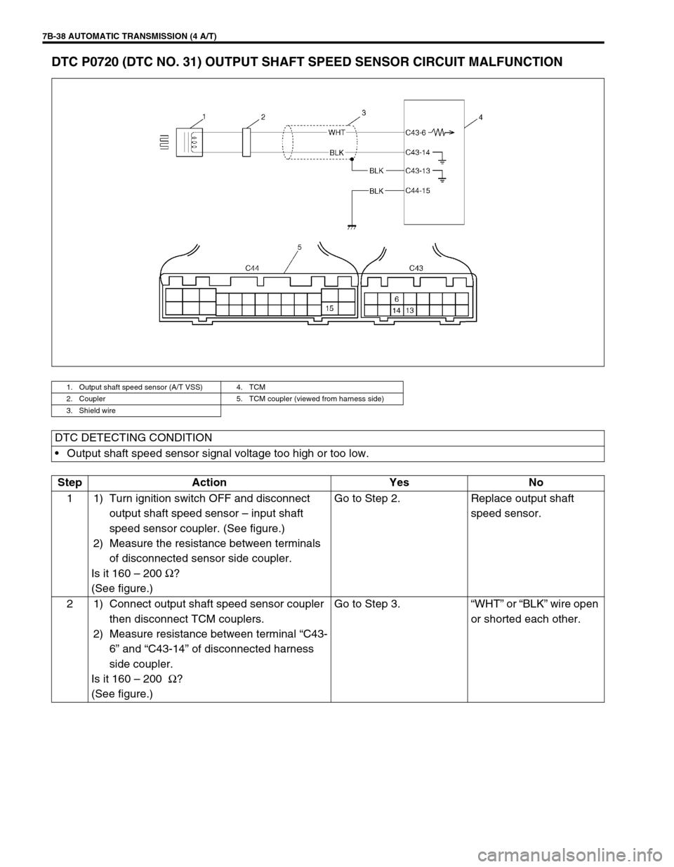
DTC P0720 (DTC NO. 31) OUTPUT SHAFT SPEED SENSOR CIRCUIT MALFUNCTION
1. Output shaft speed sensor (A/T VSS) 4. TCM
2. Coupler 5. TCM coupler (viewed from harness side)
3. Shield wire
DTC DETECTING CONDITION
Output shaft speed sensor signal voltage too high or too low.
Step Action Yes No
1 1) Turn ignition switch OFF and disconnect
output shaft speed sensor – input shaft
speed sensor coupler. (See figure.)
2) Measure the resistance between terminals
of disconnected sensor side coupler.
Is it 160 – 200 Ω
?
(See figure.)Go to Step 2. Replace output shaft
speed sensor.
2 1) Connect output shaft speed sensor coupler
then disconnect TCM couplers.
2) Measure resistance between terminal “C43-
6” and “C43-14” of disconnected harness
side coupler.
Is it 160 – 200 Ω
?
(See figure.)Go to Step 3.“WHT” or “BLK” wire open
or shorted each other.
Page 83 of 447
AUTOMATIC TRANSMISSION (4 A/T) 7B-41
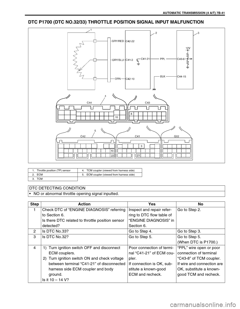
DTC P1700 (DTC NO.32/33) THROTTLE POSITION SIGNAL INPUT MALFUNCTION
1. Throttle position (TP) sensor 4. TCM coupler (viewed from harness side)
2. ECM 5. ECM coupler (viewed from harness side)
3. TCM
DTC DETECTING CONDITION
NO or abnormal throttle opening signal inputted.
Step Action Yes No
1 Check DTC of “ENGINE DIAGNOSIS” referring
to Section 6.
Is there DTC related to throttle position sensor
detected?Inspect and repair refer-
ring to DTC flow table of
“ENGINE DIAGNOSIS” in
Section 6.Go to Step 2.
2 Is DTC No.33? Go to Step 4. Go to Step 3.
3 Is DTC No.32? Go to Step 5. Go to Step 5.
(When DTC is P1700.)
4 1) Turn ignition switch OFF and disconnect
ECM couplers.
2) Turn ignition switch ON and check voltage
between terminal “C41-21” of disconnected
harness side ECM coupler and body
ground.
Is it 10 – 14 V?Poor connection of termi-
nal “C41-21” of ECM cou-
pler.
If connection is OK, sub-
stitute a known-good
ECM and recheck.“PPL” wire open or poor
connection of terminal
“C43-8” of TCM coupler.
If wire and connection are
OK, substitute a known-
good TCM and recheck.
Page 85 of 447
AUTOMATIC TRANSMISSION (4 A/T) 7B-43
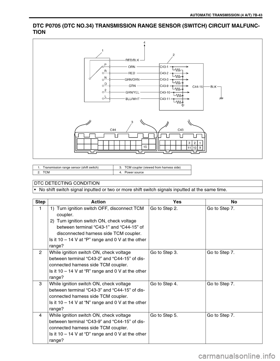
DTC P0705 (DTC NO.34) TRANSMISSION RANGE SENSOR (SWITCH) CIRCUIT MALFUNC-
TION
1. Transmission range sensor (shift switch) 3. TCM coupler (viewed from harness side)
2. TCM 4. Power source
DTC DETECTING CONDITION
No shift switch signal inputted or two or more shift switch signals inputted at the same time.
Step Action Yes No
1 1) Turn ignition switch OFF, disconnect TCM
coupler.
2) Turn ignition switch ON, check voltage
between terminal “C43-1” and “C44-15” of
disconnected harness side TCM coupler.
Is it 10 – 14 V at “P” range and 0 V at the other
range?Go to Step 2. Go to Step 7.
2 While ignition switch ON, check voltage
between terminal “C43-2” and “C44-15” of dis-
connected harness side TCM coupler.
Is it 10 – 14 V at “R” range and 0 V at the other
range?Go to Step 3. Go to Step 7.
3 While ignition switch ON, check voltage
between terminal “C43-3” and “C44-15” of dis-
connected harness side TCM coupler.
Is it 10 – 14 V at “N” range and 0 V at the other
range?Go to Step 4. Go to Step 7.
4 While ignition switch ON, check voltage
between terminal “C43-9” and “C44-15” of dis-
connected harness side TCM coupler.
Is it 10 – 14 V at “D” range and 0 V at the other
range?Go to Step 5. Go to Step 7.
Page 87 of 447
AUTOMATIC TRANSMISSION (4 A/T) 7B-45
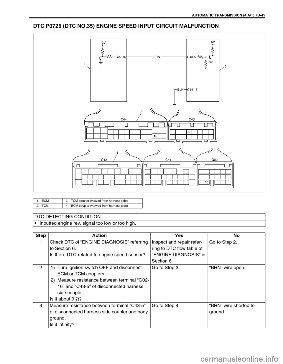
DTC P0725 (DTC NO.35) ENGINE SPEED INPUT CIRCUIT MALFUNCTION
1. ECM 3. TCM coupler (viewed from harness side)
2. TCM 4. ECM coupler (viewed from harness side)
DTC DETECTING CONDITION
Inputted engine rev. signal too low or too high.
Step Action Yes No
1 Check DTC of “ENGINE DIAGNOSIS” referring
to Section 6.
Is there DTC related to engine speed sensor?Inspect and repair refer-
ring to DTC flow table of
“ENGINE DIAGNOSIS” in
Section 6.Go to Step 2.
2 1) Turn ignition switch OFF and disconnect
ECM or TCM couplers.
2) Measure resistance between terminal “G02-
16” and “C43-5” of disconnected harness
side coupler.
Is it about 0 Ω
?Go to Step 3.“BRN” wire open.
3 Measure resistance between terminal “C43-5”
of disconnected harness side coupler and body
ground.
Is it infinity?Go to Step 4.“BRN” wire shorted to
ground