service SUZUKI SWIFT 2004 2.G Service Owners Manual
[x] Cancel search | Manufacturer: SUZUKI, Model Year: 2004, Model line: SWIFT, Model: SUZUKI SWIFT 2004 2.GPages: 1496, PDF Size: 34.44 MB
Page 888 of 1496
Downloaded from www.Manualslib.com manuals search engine 6C-6 Power Assisted Steering System:
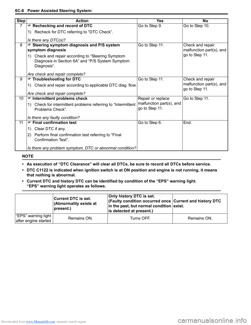
NOTE
• As execution of “DTC Clearance” will clear all DTCs, be sure to record all DTCs before service.
• DTC C1122 is indicated when ignition switch is at ON position and engine is not running, it means
that nothing is abnormal.
• Current DTC and history DTC ca n be identified by condition of the “EPS” warning light.
“EPS” warning light operates as follows.
7 �) Rechecking and record of DTC
1) Recheck for DTC referring to “DTC Check”.
Is there any DTC(s)? Go to Step 9. Go to Step 10.
8 �) Steering symptom diagnosis and P/S system
symptom diagnosis
1) Check and repair according to “Steering Symptom Diagnosis in Section 6A” and “P/S System Symptom
Diagnosis”.
Are check and repair complete? Go to Step 11. Check and repair
malfunction part(s), and
go to Step 11.
9 �) Troubleshooting for DTC
1) Check and repair according to applicable DTC diag. flow.
Are check and repair complete? Go to Step 11. Check and repair
malfunction part(s), and
go to Step 11.
10 �) Intermittent problems check
1) Check for intermittent problems referring to “Intermittent Problems Check”.
Is there any faulty condition? Repair or replace
malfunction part(s), and
go to Step 11.
Go to Step 11.
11 �) Final confirmation test
1) Clear DTC if any.
2) Perform final confirmation test referring to “Final Confirmation Test”.
Is there any problem symptom, DTC or abnormal condition? Go to Step 6. End.
Step Action Yes No
Current DTC is set.
(Abnormality exists at
present.)
Only history DTC is set.
(Faulty condition occurred once
in the past, but normal condition
is detected at present.)
Current and history DTC
exist.
“EPS” warning light
after engine started Remains ON. Turns OFF. Remains ON.
Page 931 of 1496
Downloaded from www.Manualslib.com manuals search engine Power Assisted Steering System: 6C-49
Special Tools and Equipment
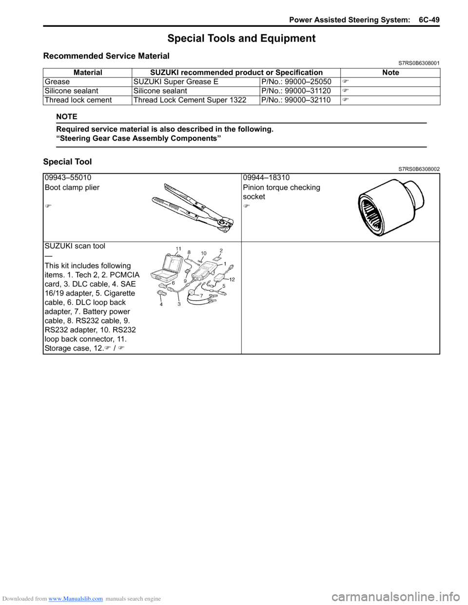
Recommended Service MaterialS7RS0B6308001
NOTE
Required service material is also described in the following.
“Steering Gear Case Assembly Components”
Special ToolS7RS0B6308002
Material SUZUKI recommended product or Specification Note
Grease SUZUKI Super Grease E P/No.: 99000–25050�)
Silicone sealant Silicone sealant P/No.: 99000–31120�)
Thread lock cement Thread Lock Cement Super 1322 P/No.: 99000–32110 �)
09943–5501009944–18310
Boot clamp plier Pinion torque checking
socket
�)�)
SUZUKI scan tool
—
This kit includes following
items. 1. Tech 2, 2. PCMCIA
card, 3. DLC cable, 4. SAE
16/19 adapter, 5. Cigarette
cable, 6. DLC loop back
adapter, 7. Battery power
cable, 8. RS232 cable, 9.
RS232 adapter, 10. RS232
loop back connector, 11.
Storage case, 12. �) / �)
Page 934 of 1496

Downloaded from www.Manualslib.com manuals search engine 7-ii Table of Contents
Recommended Service Material ....................... 7B-33
Special Tool ...................................................... 7B-33
Automatic Type .................... .................................7B-34
Precautions.........................................................7B-34 A/C System Caution .......................................... 7B-34
Precautions in Diagnosing Trouble ................... 7B-34
Precautions on Servicing A/C System .............. 7B-34
General Description .......... .................................7B-34
Auto A/C System Descript ion ............................ 7B-34
HVAC Control Module Operation Description ... 7B-36
Refrigerant Type Identifica tion .......................... 7B-36
Sub-Cool A/C System Description .................... 7B-36
A/C Operation Description ................................ 7B-36
On-Board Diagnostic System Description ......... 7B-37
Schematic and Routing Diagram ......................7B-37 Major Components of A/C System .................... 7B-37
A/C System Wiring Diagra m ............................. 7B-38
Diagnostic Information and Procedures ..........7B-39 A/C System Symptom Diagnosis ...................... 7B-39
Abnormal Noise Sympto m Diagnosis of A/C
System ............................................................ 7B-42
DTC Check........................................................ 7B-42
DTC Clearance ................................................. 7B-43
DTC Table ......................................................... 7B-44
Fail-Safe Table ................. ................................. 7B-45
Scan Tool Data ................................................. 7B-46
Air Conditioning System Check......................... 7B-47
Visual Inspection ............................................... 7B-49
DTC B1502: Inside Air Temperature Sensor and/or Its Circuit Malfunction .......................... 7B-49
DTC B1503: A/C Evaporator Air Temperature Sensor and/or Its Circuit Malfunction .............. 7B-50
DTC B1504: Sunload Sensor and/or Its Circuit Malfunction ......... ................................. 7B-52
DTC B1511: Temperature Control Actuator (Position Sensor) and/or Its Circuit
Malfunction ...................................................... 7B-53
DTC B1512: Air flow Control Actuator (Position Sensor) and/or Its Circuit
Malfunction ...................................................... 7B-55
DTC B1513: Temperature Control Actuator and/or Its Circuit Malfunction .......................... 7B-57
DTC B1514: Air Flow Co ntrol Actuator and/or
Its Circuit Malfunction ...................................... 7B-60
DTC B1541: HVAC Control Module Back-Up Power Supply Malfunction .............................. 7B-62
DTC B1546: A/C Refrigerant Pressure Malfunction ...................................................... 7B-63
DTC B1551: Serial Communication Circuit Malfunction ...................................................... 7B-63
DTC B1552: Serial Communication Signal Malfunction ...................................................... 7B-64
DTC B1553: CAN Communication Signal Malfunction ...................................................... 7B-65
DTC B1557: Vehicle Speed Sensor Signal Malfunction ...................................................... 7B-65
DTC B1561: Engine Coolant Temperature Sensor Signal Malfunctio n .............................. 7B-66 DTC B1562: Outside Air Temperature Sensor
Signal Malfunction ........................................... 7B-66
DTC B1563: A/C Refr igerant Pressure
Sensor Signal Malfunction .............................. 7B-66
Inspection of HVAC Control Module and Its Circuit .............................................................. 7B-67
A/C System Performance Inspection ................ 7B-70
A/C System Inspection at ECM ......................... 7B-70
Repair Instructions ............ ................................7B-71
Operation Procedure for Refrigerant Charge .... 7B-71
HVAC Unit Components ................................... 7B-72
HVAC Unit Removal and In stallation ................ 7B-73
Temperature Control Actuator Removal and Installation ....................................................... 7B-73
Temperature Control Actuat or Inspection ......... 7B-73
Air Flow Control Actuator Removal and Installation ....................................................... 7B-74
Air Flow Control Actuator Inspection ................. 7B-74
Air Intake Control Actuator Removal and Installation ....................................................... 7B-75
Air Intake Control Actuator Inspection............... 7B-75
Actuator Linkage Inspection .............................. 7B-76
Blower Motor Controller Removal and Installation ....................................................... 7B-76
Blower Motor Controller Inspection ................... 7B-76
HVAC Control Module Removal and Installation ....................................................... 7B-77
Sunload Sensor Removal and Installation ........ 7B-77
Sunload Sensor Inspection ............................... 7B-77
Outside Air Temperature Sensor Removal and Installation ................................................ 7B-77
Outside Air Temperature Sensor Inspection ..... 7B-77
Inside Air Temperature Sensor Removal and Installation ....................................................... 7B-78
Inside Air Temperature Sens or Inspection ........ 7B-78
Condenser Assembly On-Vehicle Inspection .... 7B-78
Condenser Assembly Removal and Installation ....................................................... 7B-78
Receiver/Dryer Removal and Installation .......... 7B-78
Evaporator Inspection ....................................... 7B-78
Evaporator Temperature Sensor Removal and Installation ................................................ 7B-78
Evaporator Temperature Se nsor Inspection ..... 7B-78
Expansion Valve Removal an d Installation ....... 7B-78
Expansion Valve Inspection .............................. 7B-78
A/C Refrigerant Pressure Sensor and Its Circuit Inspection............................................. 7B-78
A/C Refrigerant Pressu re Sensor Removal
and Installation ................................................ 7B-78
Compressor Relay Inspection .
.......................... 7B-78
Compressor Drive Belt Inspection and Adjustment ...................................................... 7B-78
Compressor Drive Belt Removal and Installation ....................................................... 7B-79
Compressor Assembly Removal and Installation ....................................................... 7B-79
Compressor Assembly Components................. 7B-79
Magnet Clutch Removal and Installation........... 7B-79
Magnet Clutch Inspection.................................. 7B-79
Relief Valve Inspection...................................... 7B-79
Page 946 of 1496
Downloaded from www.Manualslib.com manuals search engine 7A-10 Heater and Ventilation:
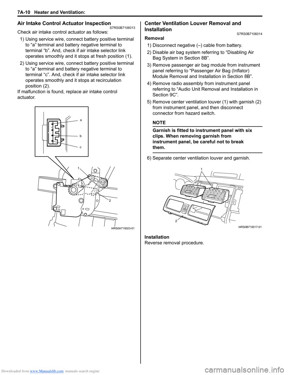
Air Intake Control Actuator InspectionS7RS0B7106013
Check air intake control actuator as follows:1) Using service wire, connect battery positive terminal to “a” terminal and battery negative terminal to
terminal “b”. And, check if air intake selector link
operates smoothly and it st ops at fresh position (1).
2) Using service wire, connect battery positive terminal to “a” terminal and battery negative terminal to
terminal “c”. And, check if air intake selector link
operates smoothly and it stops at recirculation
position (2).
If malfunction is found, replace air intake control
actuator.
Center Ventilation Louver Removal and
Installation
S7RS0B7106014
Removal
1) Disconnect negative (–) cable from battery.
2) Disable air bag system referring to “Disabling Air Bag System in Section 8B”.
3) Remove passenger air bag module from instrument panel referring to “Passenger Air Bag (Inflator)
Module Removal and Installation in Section 8B”.
4) Remove radio assembly from instrument panel referring to “Audio Unit Re moval and Installation in
Section 9C”.
5) Remove center ventilation louver (1) with garnish (2) from instrument panel, and then disconnect
connector from hazard switch.
NOTE
Garnish is fitted to in strument panel with six
clips. When removing garnish from
instrument panel, be careful not to break
them.
6) Separate center ventilation louver and garnish.
Installation
Reverse removal procedure.
a
b
c
1
2
I4RS0A710023-01
1
2
I4RS0B710017-01
Page 949 of 1496
Downloaded from www.Manualslib.com manuals search engine Air Conditioning System: Manual Type 7B-1
HVAC
Air Conditioning System
Manual Type
Precautions
A/C System CautionS7RS0B7210001
CAUTION!
• The air conditioning system of this vehicle uses refrigerant HFC-134a (R-134a).
None of refrigerant, compressor oil and component parts is interchangeable between two types of
A/C: one using refrigerant HFC-134a (R-134a) and the other using refrigerant CFC-12 (R-12).
Be sure to check which refrigerant is used be fore any service work including inspection and
maintenance. For identification between these two types, refer to “Refrigerant Type Identification”.
When replenishing or changing refrigerant and comp ressor oil and when replacing parts, make sure
that the material or the part to be used is appropriate to the A/C installed in the vehicle being
serviced.
Use of incorrect one will result in leakage of refrigerant, damage in parts or other faulty condition.
• When servicing the compressor, keep dirt or foreign material away from getting on or into the compressor parts and system. Clean tools and a clean work area are important for proper service.
The compressor connection and the outside of the compressor should be cleaned before any “On
vehicle” repair or before removal of the compressor. The parts must be kept clean at all times and
any parts to be reassembled should be cleaned with trichloromethane, naphtha, kerosene or
equivalent solvent and dried with dry air. Use only lint free cloths to wipe parts.
• When compressor is removed from the vehicle for servicing, the oil remaining in the compressor
should be discarded and new refrigerant oil added to the compressor.
Minor repair procedures may be done on the vehicle without discharging the system. Major repair
procedures require that the system be discharged of refrigerant.
Precautions on Servicing A/C SystemS7RS0B7210002
WARNING!
Should refrigerant HFC-134a (R-134a) is exposed to your eye(s), consult a doctor immediately.
• Do not use your hand to rub affected eye(s). Instead, use fresh cold water to splash it over affected area to thus gradually raise its temperature above the freezing point.
• Obtain proper treatment as soon as possible from a doctor or eye specialist. Should liquid refrigerant HFC-134a (R-134a) is exposed to your skin, such affected part should be treated in the
same manner as when skin is frostbitten or frozen.
Handling Refrigerant HFC-134a (R-134a)
• Always wear goggles to protect your eyes.
• Avoid direct contact to liquid refrigerant.
• Do not heat refrigerant container higher than 40 °C (104 ° F).
• Do not discharge refrigerant into atmosphere.
• Do not expose bright metals to liquid refrigerant. Refrig erant combined with moisture is corrosive and tarnishes
surfaces of bright metals including chrome.
Page 951 of 1496
Downloaded from www.Manualslib.com manuals search engine Air Conditioning System: Manual Type 7B-3
General Description
Refrigerant Type IdentificationS7RS0B7211001
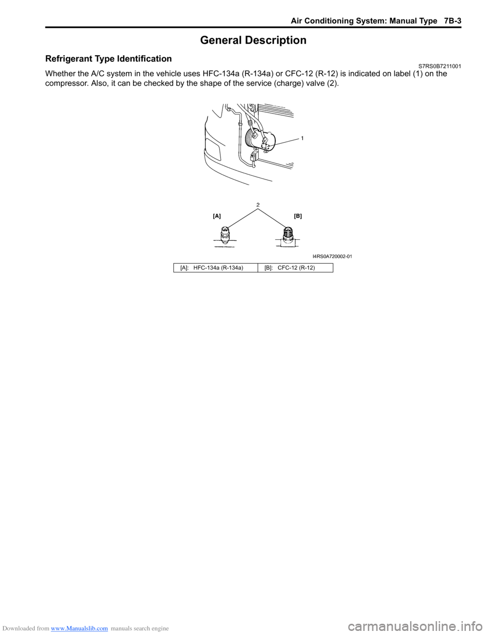
Whether the A/C system in the vehicle uses HFC-134a (R-134a) or CFC-12 (R-12) is indicated on label (1) on the
compressor. Also, it can be checked by th e shape of the service (charge) valve (2).
[A]: HFC-134a (R-134a) [B]: CFC-12 (R-12)
I4RS0A720002-01
Page 958 of 1496

Downloaded from www.Manualslib.com manuals search engine 7B-10 Air Conditioning System: Manual Type
Abnormal Noise from Tension Pulley
Abnormal Noise from A/C Evaporator
Abnormal Noise from Blower Motor
A/C System Performance InspectionS7RS0B7214003
1) Confirm that vehicle and environmental conditions are as follows.
• Vehicle is put indoors.
• Ambient temperature is within 25 – 35 °C (77 – 95
° F).
• Relative humidity is within 30 – 70%.
• There is no wind indoors.
• HVAC unit is normal.
• Blower motor is normal.
• There is no air leakage from air ducts.
• Condenser fins are clean.
• Air filter in HVAC unit is not clogged with dirt and
dust.
• Battery voltage is about 12 V.
• Radiator cooling fan operates normally.
2) Make sure that high pressure valve (1) and low pressure valve (2) of manifold gauge are firmly
closed.
3) Connect high pressure charging hose (3) to high pressure service valve (5) on vehicle and low
pressure charging hose (4) to low pressure service
valve (6).
4) Bleed the air in charging hoses (3) and (4) by loosening their nuts respectively utilizing the
refrigerant pressure. When a hissing sound is heard,
immediately tighten nut.
CAUTION!
Do not connect high and low pressure
charging hoses in reverse.
Condition Possible cause Correction / Reference Item
Clattering noise is heard
from pulley Worn or damaged bearing
Replace tension pulley.
Pulley cranks upon
contact Cracked or loose bracket
Replace or retighten bracket.
ConditionPossible cause Correction / Reference Item
Whistling sound is heard
from A/C evaporator Depending on the combination of the
interior / exterior temperatures, engine
rpm and refrigerant pressure, the
refrigerant flowing out of the expansion
valve may, under certain conditions,
make a whistling sound At times, slightly decrea
sing refrigerant volume
may stop this noise.
Inspect expansion valve and replace if faulty.
Condition Possible cause Correction / Reference Item
Blower motor emits a
chirping sound in
proportion to its speed of
rotation Worn or damaged motor brushes or
commutator
Replace blower motor.
Fluttering noise or large
droning noise is heard
from blower motor Leaves or other debris introduced from
fresh air inlet to blower motor
Remove debris and make sure that the screen
at fresh air inlet is intact.
53
2
1
4 6
I4RS0A720006-01
Page 967 of 1496
Downloaded from www.Manualslib.com manuals search engine Air Conditioning System: Manual Type 7B-19
Charge
CAUTION!
• Because the sight glass is not used for this A/C system, do not perform an additional
charge to the A/C system. To charge the
proper amount of refrigerant, recover and
evacuate the A/C system first. And then,
charge the proper amount of refrigerant
into the A/C system.
• Always charge refrigerant through low pressure side of A/C system after the initial
charge is performed from the high
pressure side with the engine stopped.
• Never charge refrigerant through high pressure side of A/C system with engine
running.
• Do not charge refrigerant while compressor is hot.
• When installing tap valve to refrigerant container to make a hole there through,
carefully follow dire ctions given by
manufacturer.
• A pressure gauge should always be used before and during refrigerant charge.
• The refrigerant container should be emptied of refrigerant when discarding it.
• The refrigerant container should not be heated up to 40 °C (104 °F) or over.
• Refrigerant container should not be reversed in direction during refrigerant
charge. Reversing in direction causes
liquid refrigerant to enter compressor,
causing troubles, such as compression of
liquid refrigerant and the like.
NOTE
The air conditioning system contains HFC-
134a (R-134a).
Described here is a method to charge the air
conditioning system with refrigerant from the
refrigerant service container.
When charging refrigerant recovered by
using the refrigerant and recycling
equipment (when recycling refrigerant),
follow the procedure described in the
equipment manufacturer’s instruction
manual.
Charge proper amount of refrigerant accurately in
accordance with the following procedure.
Specified amount of refrigerant
370 ± 20 g (13.0 ± 0.7 oz)
The initial charge of the A/C system is performed
through the high pressure side with the engine stopped.
And next, this method must be followed by charging from
the low pressure side with the engine running.
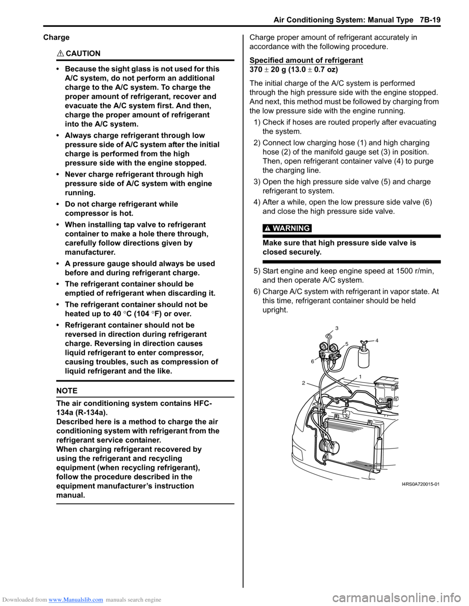
1) Check if hoses are routed properly after evacuating the system.
2) Connect low charging hose (1) and high charging hose (2) of the manifold gauge set (3) in position.
Then, open refrigerant container valve (4) to purge
the charging line.
3) Open the high pressure side valve (5) and charge refrigerant to system.
4) After a while, open the low pressure side valve (6) and close the high pressure side valve.
WARNING!
Make sure that high pressure side valve is
closed securely.
5) Start engine and keep engine speed at 1500 r/min, and then operate A/C system.
6) Charge A/C system with refrigerant in vapor state. At this time, refrigerant container should be held
upright.
1
2 6 3
5 4
I4RS0A720015-01
Page 969 of 1496
Downloaded from www.Manualslib.com manuals search engine Air Conditioning System: Manual Type 7B-21
Removal of Manifold Gauge Set
WARNING!
High pressure side is under high pressure.
Therefore, be careful not to get injured
especially on your eyes and skin.
For the A/C system charged with the specified amount of
refrigerant, remove manifold gauge set as follows:
1) Close low pressure side valve of manifold gauge set. (The high pressure side valve is closed continuously
during the process of charging.)
2) Close refrigerant container valve.
3) Stop engine.
4) Using shop rag, remove charging hoses from service valves. This operation must be performed quickly.
5) Put caps on service valves.
Check A/C System for Refrigerant Leaks
Whenever a refrigerant leak is suspected in the system
or any service operation has been performed which may
result in malfunction of lines and connections, it is
advisable to check for leaks.
Common sense should be used during refrigerant leak
test, since the need and extent of any such test will, in
general, depend upon the nature of a complaint and the
type of a service performed on the system.
Liquid leak detector
WARNING!
• To prevent explosions and fires, make sure that there are no flammables in the vicinity.
• When the refrigerant exposed to fire, it turns into a poisonous gas (phosgene). Do
not inhale this gas.
There is a number of fittings and places throughout the
A/C system where a liquid leak detector solution may be
used to pinpoint refrigerant leaks.
By merely applying the solution to the area in question
with a swab, such as attached to the cap of a vial,
bubbles will form within seconds if there is a leak.
For confined areas, such as sections of the evaporator
and condenser, an electronic (refrigerant) leak detector
is more practical fo r determining leaks.
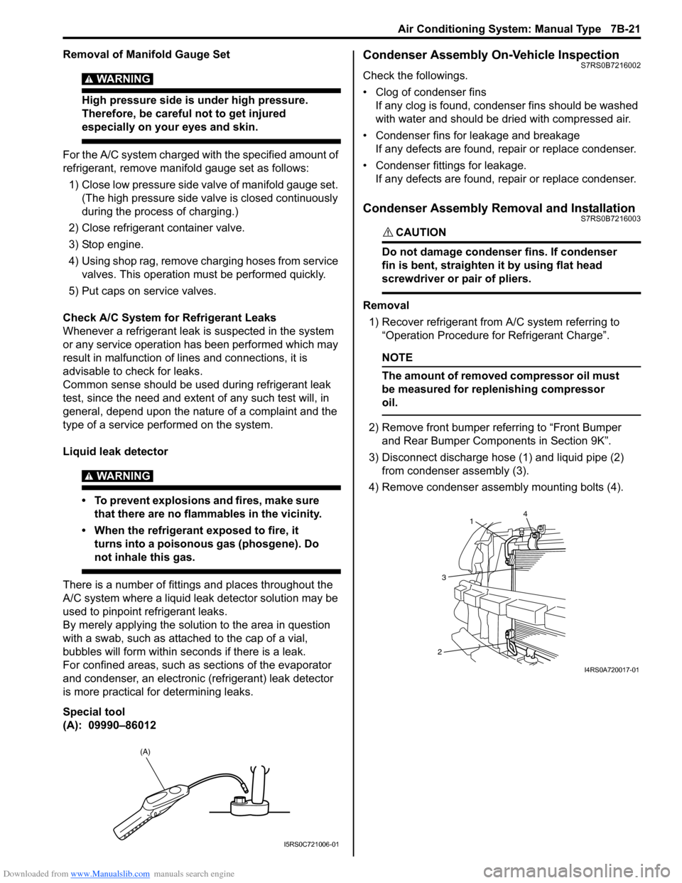
Special tool
(A): 09990–86012
Condenser Assembly On-Vehicle InspectionS7RS0B7216002
Check the followings.
• Clog of condenser fins If any clog is found, cond enser fins should be washed
with water and should be dried with compressed air.
• Condenser fins for leakage and breakage If any defects are found, repair or replace condenser.
• Condenser fittings for leakage. If any defects are found, repair or replace condenser.
Condenser Assembly Removal and InstallationS7RS0B7216003
CAUTION!
Do not damage condenser fins. If condenser
fin is bent, straighten it by using flat head
screwdriver or pair of pliers.
Removal
1) Recover refrigerant from A/C system referring to “Operation Procedure for Refrigerant Charge”.
NOTE
The amount of removed compressor oil must
be measured for replenishing compressor
oil.
2) Remove front bumper referring to “Front Bumper and Rear Bumper Components in Section 9K”.
3) Disconnect discharge hose (1) and liquid pipe (2) from condenser assembly (3).
4) Remove condenser assembly mounting bolts (4).
(A)
I5RS0C721006-01
4
1
3
2
I4RS0A720017-01
Page 981 of 1496
Downloaded from www.Manualslib.com manuals search engine Air Conditioning System: Manual Type 7B-33
Special Tools and Equipment
Recommended Service MaterialS7RS0B7218001
NOTE
Required service material is also described in the following.
“Precautions on Servicing A/C System”
Special ToolS7RS0B7218002
Material SUZUKI recommended product or Specification Note
Compressor oil MATSUSHITADEN KI GU10 P/No.: 99000–99015–
00A �)
/ �)
Silicon sealant SUZUKI SILICON SEALANT KE-
347W (100g) P/No.: 99000–34220
�)
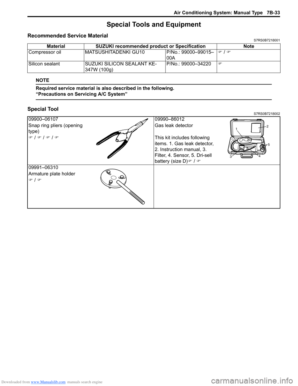
09900–06107 09990–86012
Snap ring pliers (opening
type) Gas leak detector
�) / �) / �) / �) This kit includes following
items. 1. Gas leak detector,
2. Instruction manual, 3.
Filter, 4. Sensor, 5. Dri-sell
battery (size D)�) / �)
09991–06310
Armature plate holder
�) / �)
1 2
3 4
5