fuse diagram SUZUKI SWIFT 2004 2.G Service Workshop Manual
[x] Cancel search | Manufacturer: SUZUKI, Model Year: 2004, Model line: SWIFT, Model: SUZUKI SWIFT 2004 2.GPages: 1496, PDF Size: 34.44 MB
Page 1256 of 1496
Downloaded from www.Manualslib.com manuals search engine 9A-85 Wiring Systems:
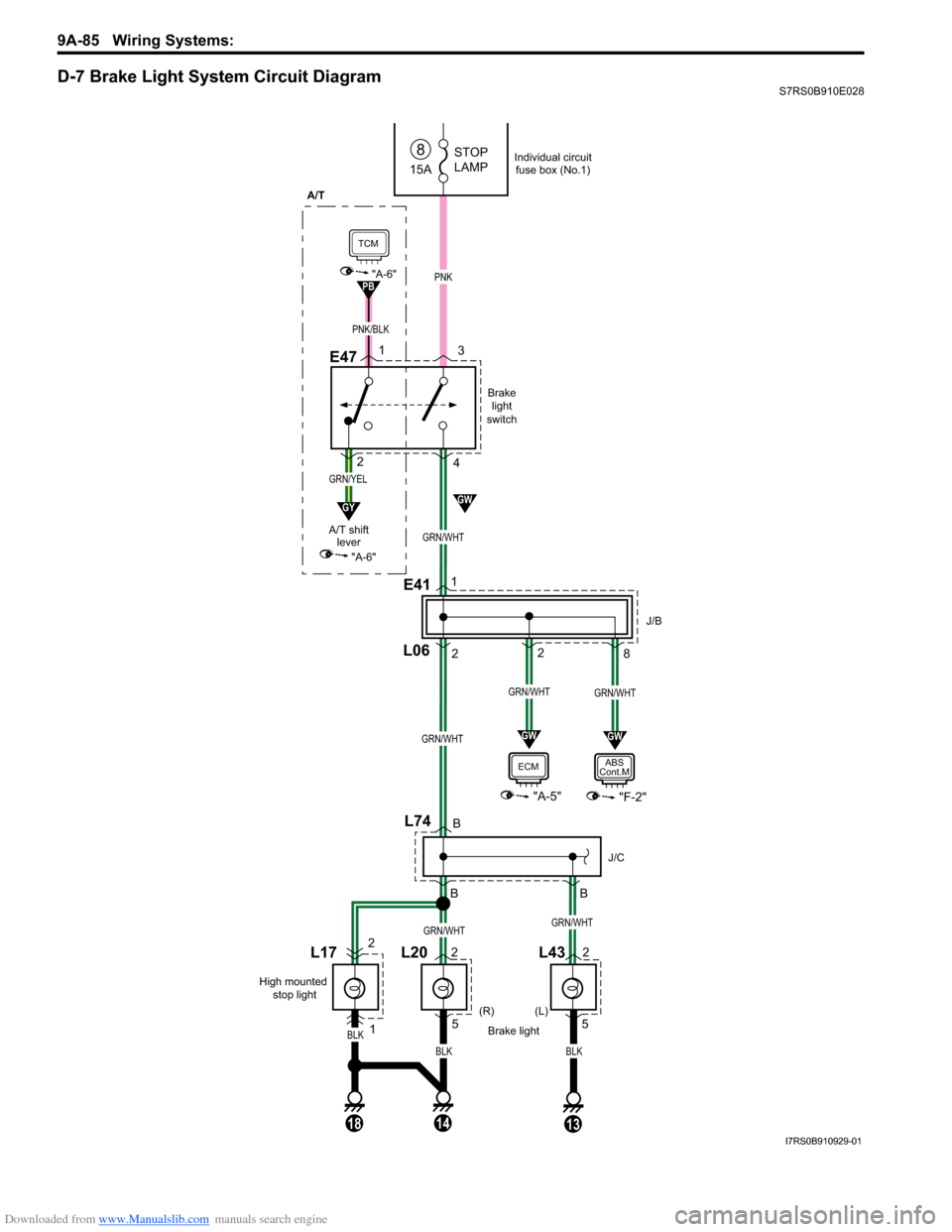
D-7 Brake Light System Circuit DiagramS7RS0B910E028
Brakelight
switch
(R)
Brake light
PNK
BLK
(L)
15A
8STOP
LAMP
E47
L43
GRN/WHT
GRN/WHT
GRN/WHT
5
4
1
L0628
E411
J/B
"F-2"
ABS
Cont.M
GRN/WHT
2
"A-5"
ECM
13
GW
GWGW
TCM
PB
PNK/BLK
"A-6"
GRN/YEL
A/T shift
lever
GY
"A-6"
2 3
A/T
18
Individual circuit
fuse box (No.1)
B
BL74
J/C
L202
5L172
1
High mounted stop light
14
BLK
BLK
2
B
GRN/WHTGRN/WHT
I7RS0B910929-01
Page 1266 of 1496
Downloaded from www.Manualslib.com manuals search engine 9A-95 Wiring Systems:
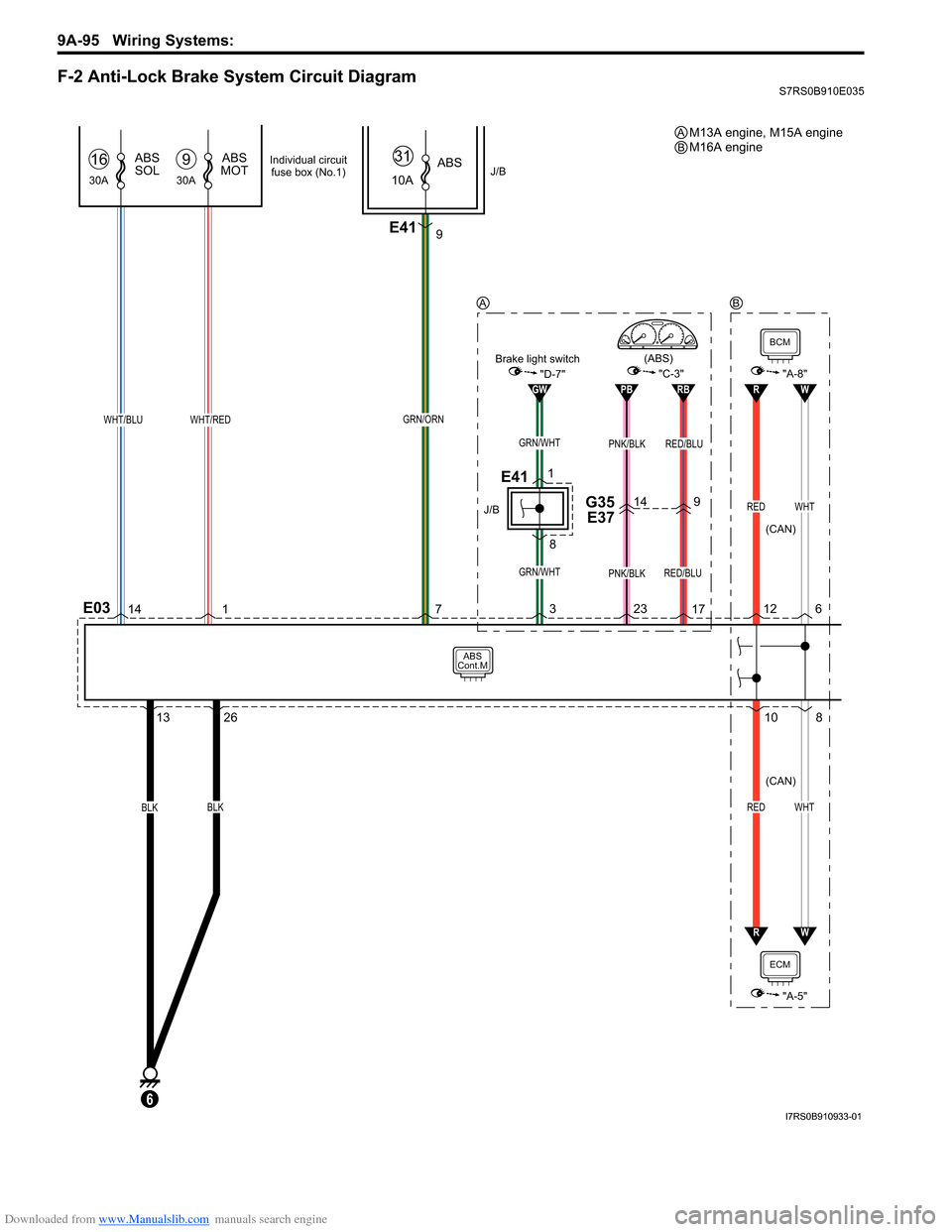
F-2 Anti-Lock Brake System Circuit DiagramS7RS0B910E035
1326
14
1 3
23
17
E03
ABS
Cont.M
BCM
BLK
30A
ABS
SOL16
30A
ABS
MOT9
WHT/REDWHT/BLU
GRN/WHT
6
BLKREDWHT
PNK/BLK
PB
PNK/BLK
RB
RED/BLU
RED/BLU
149G35 E37
"C-3""A-8"
ECM
"A-5"
J/B10A ABS
31
E419
GRN/ORN
7
GW"D-7"Brake light switch
(CAN)
(CAN)
(ABS)
GRN/WHT
J/B
E411
8
Individual circuit fuse box (No.1)
108
12
RED
R
6
WHT
W
RW
M13A engine, M15A engine
M16A engineA
AB
B
I7RS0B910933-01
Page 1268 of 1496
Downloaded from www.Manualslib.com manuals search engine 9A-97 Wiring Systems:
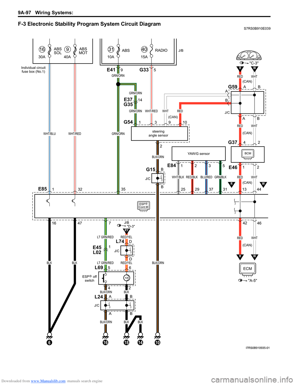
F-3 Electronic Stability Program System Circuit DiagramS7RS0B910E039
1647
132 13
44E85
BLK
ABS
SOLABS
MOT
WHT/REDWHT/BLU
6
BLK
REDWHT
REDWHT
REDWHT
25
BLK/ORN
GRN/ORN
GRN/ORN
GRN/ORN
Individual circuit
fuse box (No.1) J/B
ABS
GRN/ORN
ECM
35
"A-5"
"C-3"
steering
angle sensor
RED
R
4246
WHT
W
RW
1
4G37
E46
2
2
BCM
A
A
A
BG59
B
B
RW
2
1
WHT/REDWHTRED
3910
(CAN) (CAN)
(CAN)
(CAN)
(CAN)
7
ESP
Cont.M
1E45 L02
LT GRN/RED
LT GRN/REDRED/YEL
RED/YEL
BLK/ORN
WHT/BLK
RY
J/C J/C
B
BLKBLK
BLK/ORN
BLK/ORN
16181410
BLK
ESP off
switch
L6956
42
G15
G541
29
RED/BLK
2
37
BLU/RED
3
31
GRN/BLK
5E84B
J/C
D
L74D
R
R
"D-3"J/B
YAW/G sensor
J/C
A
L24A
B
B
30A
16
40A
9
10A
31
15A
RADIO
40
E419G335
E37
G3514
I7RS0B910935-01
Page 1270 of 1496
Downloaded from www.Manualslib.com manuals search engine 9A-99 Wiring Systems:
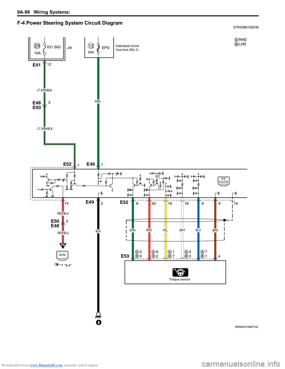
F-4 Power Steering System Circuit DiagramS7RS0B910E036
P/S
Cont.M
50AEPS12
E4112
J/B
10A IG1 SIG
29
RED
20
E48
E50
E50
E48
Torque sensor
BLK
E49
8
GRN
LT GRN/BLK
YEL
16
GRN
8
BRN
49
WHT
18
BLU
619
1
21
LT GRN/BLK
3
E53
E49
E52
E52
RB
5
ECM
"A-5"
RED/BLU
RED/BLU
14
Individual circuit
fuse box (No.1)
RHD
LHDAB
AB2
6AB6
2AB1
7AB5
3AB7
1
I5RS0C910957-02
Page 1299 of 1496
Downloaded from www.Manualslib.com manuals search engine Instrumentation / Driver Info. / Horn: 9C-4
Schematic and Routing Diagram
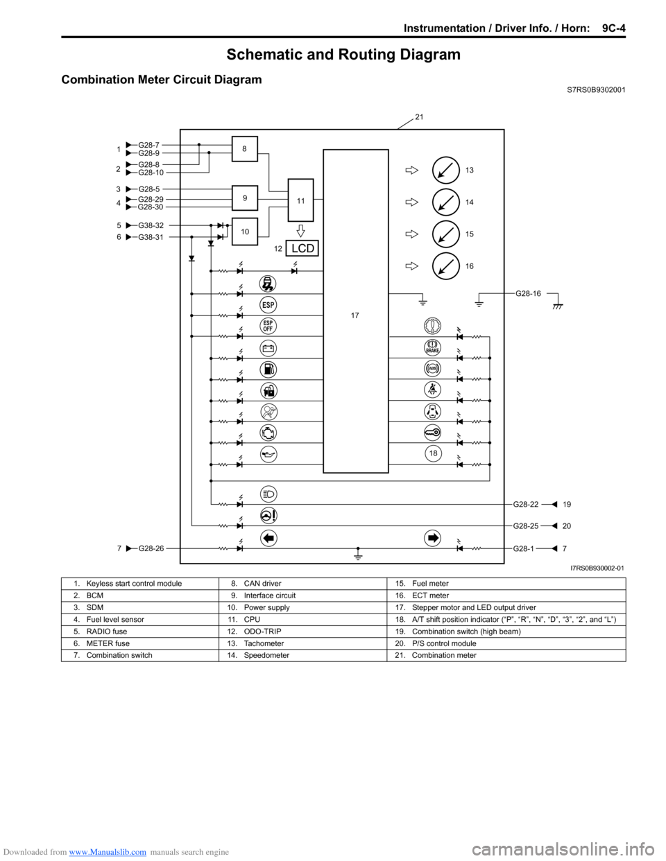
Combination Meter Circuit DiagramS7RS0B9302001
16
15
14
13
G28-5
5
6
3
G28-26
7
G28-2219
G28-2520
G28-17
12
10 11
21
9
17
G28-304G28-29
18
G28-16
G28-9
G28-10G28-8 G28-7
1
2 8
G38-31
G38-32
I7RS0B930002-01
1. Keyless start control module
8. CAN driver 15. Fuel meter
2. BCM 9. Interface circuit 16. ECT meter
3. SDM 10. Power supply 17. Stepper motor and LED output driver
4. Fuel level sensor 11. CPU 18. A/T shift position indicator (“P”, “R”, “N”, “D”, “3”, “2”, and “L”)
5. RADIO fuse 12. ODO-TRIP 19. Combination switch (high beam)
6. METER fuse 13. Tachometer 20. P/S control module
7. Combination switch 14. Speedometer 21. Combination meter
Page 1419 of 1496
Downloaded from www.Manualslib.com manuals search engine Body Electrical Control System: 10B-16
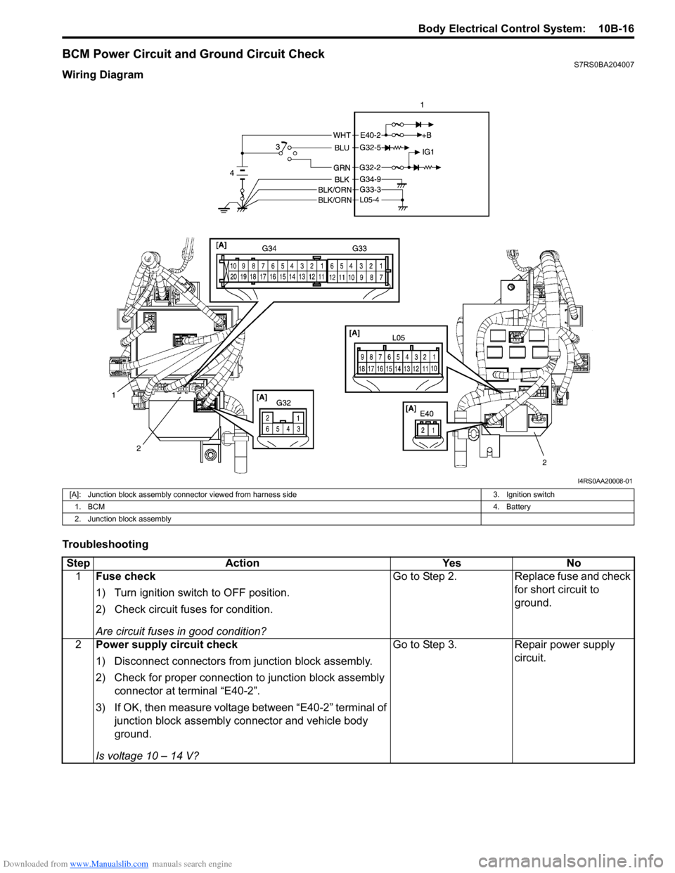
BCM Power Circuit and Ground Circuit CheckS7RS0BA204007
Wiring Diagram
Troubleshooting
I4RS0AA20008-01
[A]: Junction block assembly connector viewed from harness side3. Ignition switch
1. BCM 4. Battery
2. Junction block assembly
Step Action YesNo
1 Fuse check
1) Turn ignition switch to OFF position.
2) Check circuit fuses for condition.
Are circuit fuses in good condition? Go to Step 2.
Replace fuse and check
for short circuit to
ground.
2 Power supply circuit check
1) Disconnect connectors from junction block assembly.
2) Check for proper connection to junction block assembly
connector at terminal “E40-2”.
3) If OK, then measure voltage between “E40-2” terminal of junction block assembly connector and vehicle body
ground.
Is voltage 10 – 14 V? Go to Step 3.
Repair power supply
circuit.
Page 1447 of 1496
Downloaded from www.Manualslib.com manuals search engine Immobilizer Control System: 10C-4
Schematic and Routing Diagram
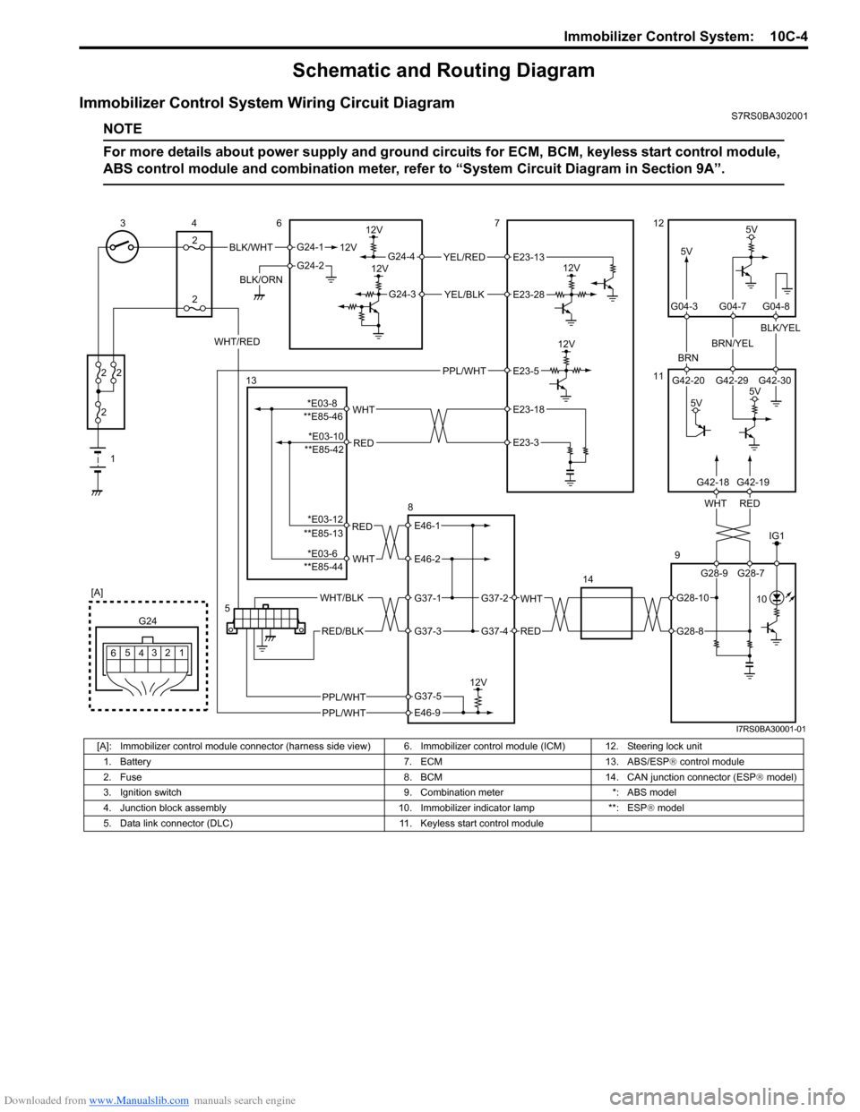
Immobilizer Control System Wiring Circuit DiagramS7RS0BA302001
NOTE
For more details about power supply and ground circuits for ECM, BCM, keyless start control module,
ABS control module and combination meter, refer to “System Ci rcuit Diagram in Section 9A”.
BLK/WHT
BLK/ORN12V
G24-1
G24-2
12V
5V
12V
12VYEL/RED
YEL/BLK
G24-4
G24-3
12V
5V
BRN
BRN/YEL
BLK/YEL
1
2
2 2
2
34
2 6712
11
9
14
12
3
4
G24
[A]
5
6
REDWHT
G42-20 G42-29 G42-30
G04-3 G04-7 G04-8
WHT/RED
5V
5V
5
G28-9 G28-7
G42-18G42-19
E23-13
E23-28
IG1
PPL/WHT 10
PPL/WHT
PPL/WHT
E23-5
RED
WHT**E85-46E23-18
E23-3
RED
WHT
E46-1
E46-2
WHT
RED
G37-2
G37-4
WHT/BLK
RED/BLK
G37-1
G37-3
12V
E46-9
G37-5
13
8
**E85-42
**E85-13
**E85-44
G28-10
G28-8
*E03-8 *E03-10
*E03-12
*E03-6
I7RS0BA30001-01
[A]: Immobilizer control module connector (harness side vi ew) 6. Immobilizer control module (ICM) 12. Steering lock unit
1. Battery 7. ECM 13. ABS/ESP ® control module
2. Fuse 8. BCM 14. CAN junction connector (ESP ® model)
3. Ignition switch 9. Combination meter *: ABS model
4. Junction block assembly 10. Immobilizer indicator lamp **: ESP ® model
5. Data link connector (DLC) 11. Keyless start control module
Page 1451 of 1496
Downloaded from www.Manualslib.com manuals search engine Immobilizer Control System: 10C-8
Immobilizer Indicator Lamp Remains ON after Engine StartsS7RS0BA304007
Wiring Diagram
Refer to “Immobilizer Control S ystem Wiring Circuit Diagram”.
Circuit Description
When the ignition switch is turned ON, ECM read the code by the coil antenna from ignition key. Then if the code in
transponder in the key match with the one registered with ECM, transmits indication ON signal of immobilizer indicator
lamp to combination meter in order to turn immobilizer indicator lamp on. And then, combination meter turns
immobilizer indicator lamp on. When th e engine starts to run and no malfunction is detected in the system, ECM
transmits immobilizer indicator lamp indication O FF signal to combination meter in order to turn immobilizer indicator
lamp off. And then, comb ination meter turns immobilizer indicator lamp off, but if a malfunction was or is detected,
immobilizer indicator lamp is flashes ON and OF F, when ignition switch turn to ON position.
Troubleshooting 4
Fuse check
1) Turn ignition switch to OFF position.
2) Check for fuse blown at combination meter circuit fuse in
junction block assembly.
Is fuse in good condition? Go to Step 5. Replace fuse and check
for short to power or
ground circuit.
5 CAN communication circuit check
1) Disconnect connectors of all control modules
communicating by means of CAN.
2) Check CAN communication circuit between control modules for open, short and high resistance.
Is each CAN communication circuit in good condition? Go to Step 6. Repair circuit.
6 Combination meter power and ground circuit check
1) Remove combination meter referring to “Combination
Meter Removal and Installation in Section 9C”.
2) Check for proper connection to combination meter connector terminals.
3) If OK, then turn ignition switch to ON position, Check terminal voltage of combination meter between power
supply and ground terminal. Refer to “Combination
Meter Circuit Diagram in Section 9C”.
Is it 10 – 14 V? Substitute a known-
good combination meter
and recheck. If
immobilizer indicator
lamp still remains OFF,
substitute a known good
ECM and recheck.
Repair power supply
and/or ground circuit.
Step Action Yes No
Step
Action YesNo
1 DTC check of ECM
1) Start engine and recheck DTC of ECM while engine
running.
Is DTC P1674, P1675, P1678 and/or P1685 detected? Go to applicable DTC
diag. flow.
Go to Step 2.
2 CAN communication circuit check
1) Disconnect connectors from ECM, BCM, ABS control
module and combination meter.
2) Check CAN communication circuit for open, short and high resistance.
• Between ECM and ABS control module
• Between BCM and ABS control module
• Between BCM and combination meter
Is each CAN communication circuit in good condition? Substitute a known-
good combination meter
and recheck. If
immobilizer indicator
lamp still remains ON,
substitute a known-
good ECM and recheck.
Repair circuit.
Page 1484 of 1496
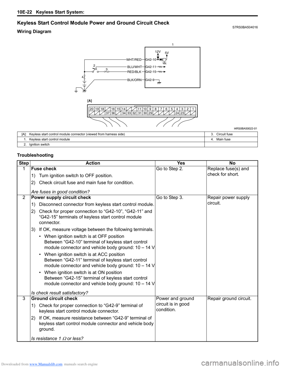
Downloaded from www.Manualslib.com manuals search engine 10E-22 Keyless Start System:
Keyless Start Control Module Power and Ground Circuit CheckS7RS0BA504016
Wiring Diagram
Troubleshooting
BLK/ORNG42-9
G42-15
G42-10
G42-11BLU/WHT
WHT/RED
RED/BLK
5V
12V
1234567891011
141516
36 34 33 32 31 30 29 24 23
37
181920
[A]
4 2
3 1
I4RS0BA50022-01
[A]: Keyless start control module connector (viewed from harness side)
3. Circuit fuse
1. Keyless start control module 4. Main fuse
2. Ignition switch
Step Action YesNo
1 Fuse check
1) Turn ignition switch to OFF position.
2) Check circuit fuse and main fuse for condition.
Are fuses in good condition? Go to Step 2.
Replace fuse(s) and
check for short.
2 Power supply circuit check
1) Disconnect connector from keyless start control module.
2) Check for proper connection to “G42-10”, “G42-11” and
“G42-15” terminals of keyless start control module
connector.
3) If OK, measure voltage between the following terminals. • When ignition switch is at OFF positionBetween “G42-10” terminal of keyless start control
module connector and vehicle body ground: 10 – 14 V
• When ignition switch is at ACC position Between “G42-11” terminal of keyless start control
module connector and vehicle body ground: 10 – 14 V
• When ignition switch is at ON position Between “G42-15” terminal of keyless start control
module connector and vehicle body ground: 10 – 14 V
Is check result satisfactory? Go to Step 3.
Repair power supply
circuit.
3 Ground circuit check
1) Check for proper connection to “G42-9” terminal of
keyless start control module connector.
2) If OK, measure resistance between “G42-9” terminal of keyless start control module connector and vehicle body
ground.
Is resistance 1
Ω or less? Power and ground
circuit is in good
condition.
Repair ground circuit.