Thermo SUZUKI SWIFT 2004 2.G Service User Guide
[x] Cancel search | Manufacturer: SUZUKI, Model Year: 2004, Model line: SWIFT, Model: SUZUKI SWIFT 2004 2.GPages: 1496, PDF Size: 34.44 MB
Page 366 of 1496
Downloaded from www.Manualslib.com manuals search engine 1F-3 Engine Cooling System:
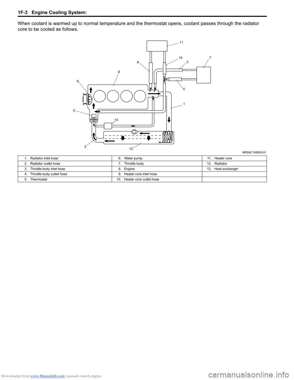
When coolant is warmed up to normal temperature and the thermostat opens, coolant passes through the radiator
core to be cooled as follows.
11
10 3 7
4
9
8
6
5
2 12 1
13
I6RS0C160002-01
1. Radiator inlet hose
6. Water pump11. Heater core
2. Radiator outlet hose 7. Throttle body12. Radiator
3. Throttle body inlet hose 8. Engine13. Heat exchanger
4. Throttle body outlet hose 9. Heater core inlet hose
5. Thermostat 10. Heater core outlet hose
Page 367 of 1496
Downloaded from www.Manualslib.com manuals search engine Engine Cooling System: 1F-4
Diagnostic Information and Procedures
Engine Cooling Symptom DiagnosisS7RS0B1604001
ConditionPossible cause Correction / Reference Item
Engine overheats
(Radiator fan operates) Loose or broken water pump belt
Adjust or replace.
Not enough coolant Check coolant level and add as necessary.
Faulty thermostat Replace.
Faulty water pump Replace.
Dirty or bent radiator fins Clean or remedy.
Coolant leakage on cooling system Repair.
Clogged radiator Check and replace radiator as necessary.
Faulty radiator cap Replace.
Improper ignition timing Adjust.
Dragging brakes Adjust brake.
Slipping clutch Adjust or replace.
Poor charge battery Check and replace as necessary.
Poor generation generator Check and repair.
ECT sensor faulty Check and replace as necessary.
Radiator cooling fan relay No.2 and/or
No.3 faulty Check and replace as necessary.
Radiator fan motor faulty Check and replace as necessary.
ECM faulty Check and replace as necessary.
Wiring or grounding faulty Repair as necessary.
Equipped with too much electric load
part(s) Dismount.
Engine overheats
(Radiator fan does not
operate) Fuse blown
Check 30 A fuse of relay/fuse box and check
for short circuit to ground.
Radiator cooling fan relay No.1 faulty Check and replace as necessary.
ECT sensor faulty Check and replace as necessary.
Radiator cooling fan motor faulty Check and replace as necessary.
Wiring or grounding faulty Repair as necessary.
ECM faulty Check and replace as necessary.
Page 368 of 1496
Downloaded from www.Manualslib.com manuals search engine 1F-5 Engine Cooling System:
Repair Instructions
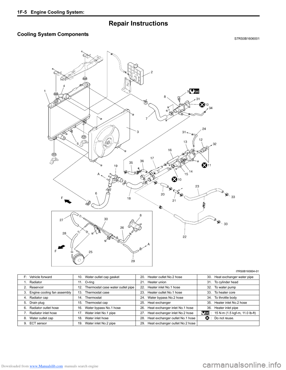
Cooling System ComponentsS7RS0B1606001
I7RS0B160004-01
F: Vehicle forward10. Water outlet cap gasket 20. Heater outlet No.2 hose 30. Heat exchanger water pipe
1. Radiator 11. O-ring 21. Heater union 31. To cylinder head
2. Reservoir 12. Thermostat case water outlet pipe 22. Heater inlet No.1 hose 32. To water pump
3. Engine cooling fan assembly 13. Thermostat case 23. Heater outlet No.1 hose33. To heater core
4. Radiator cap 14. Thermostat 24. Water bypass No.2 hose 34. To throttle body
5. Drain plug 15. Thermostat cap 25. Heat exchanger 35. Heater inlet No.2 hose
6. Radiator outlet hose 16. Water bypass No.1 hose 26.Heat exchanger inlet No.1 hose 36. Heater inlet pipe
7. Radiator inlet hose 17. Water inlet No.1 pipe 27. Heat exchanger inlet No.2 hose : 15 N⋅m (1.5 kgf-m, 11.0 lb-ft)
8. Water outlet cap 18. Water inlet hose 28. Heat exchanger outlet No.1 hose : Do not reuse.
9. ECT sensor 19. Water inlet No.2 pipe 29. Heat exchanger outlet No.2 hose
Page 370 of 1496
Downloaded from www.Manualslib.com manuals search engine 1F-7 Engine Cooling System:
Cooling System Flush and RefillS7RS0B1606005
WARNING!
To help avoid danger of being burned, do not
remove radiator cap while engine and
radiator are still hot. Scalding fluid and steam
can be blown out under pressure if cap is
taken off too soon.
NOTE
For detail of coolant specification, refer to
“Coolant Description”.
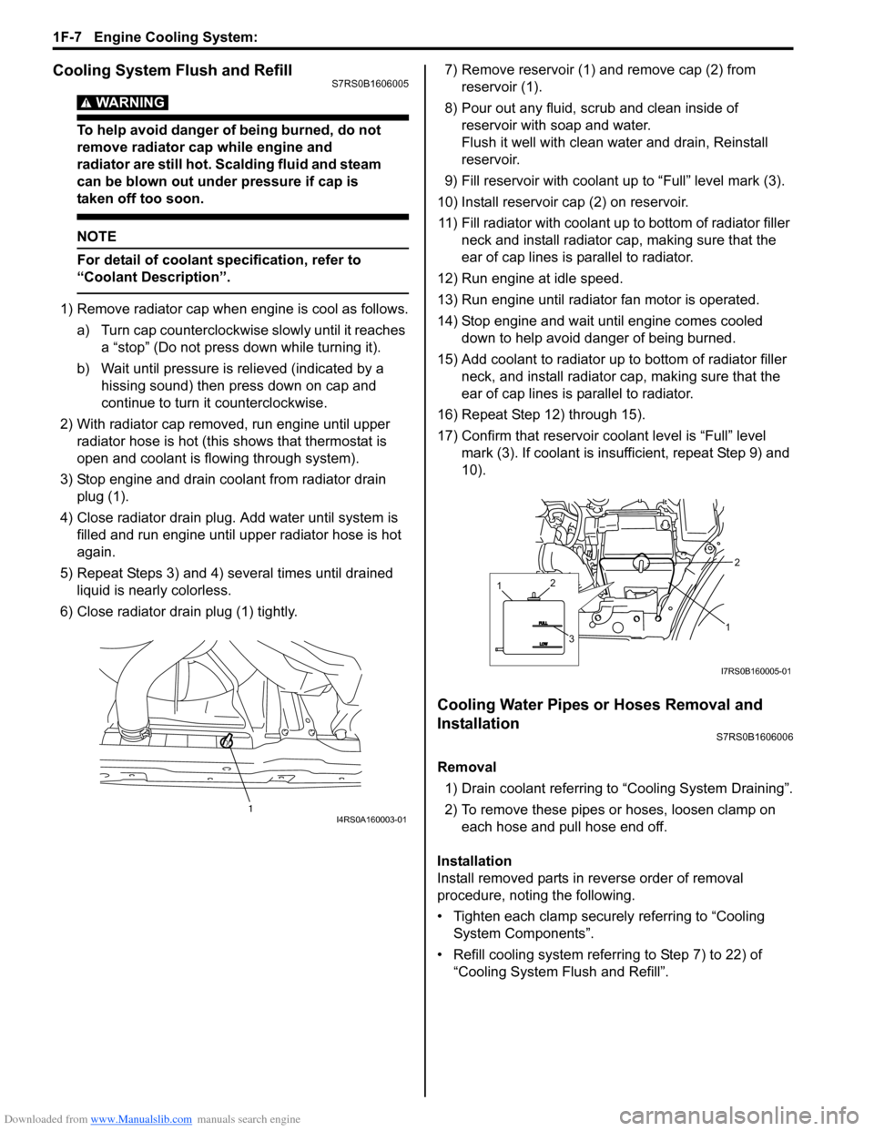
1) Remove radiator cap when engine is cool as follows.a) Turn cap counterclockwise slowly until it reaches a “stop” (Do not press down while turning it).
b) Wait until pressure is relieved (indicated by a hissing sound) then press down on cap and
continue to turn it counterclockwise.
2) With radiator cap removed, run engine until upper radiator hose is hot (this shows that thermostat is
open and coolant is flowing through system).
3) Stop engine and drain coolant from radiator drain plug (1).
4) Close radiator drain plug. Add water until system is filled and run engine until up per radiator hose is hot
again.
5) Repeat Steps 3) and 4) several times until drained liquid is nearly colorless.
6) Close radiator drain plug (1) tightly. 7) Remove reservoir (1) and remove cap (2) from
reservoir (1).
8) Pour out any fluid, scrub and clean inside of reservoir with soap and water.
Flush it well with clean water and drain, Reinstall
reservoir.
9) Fill reservoir with coolant up to “Full” level mark (3).
10) Install reservoir cap (2) on reservoir. 11) Fill radiator with coolant up to bottom of radiator filler neck and install radiator cap, making sure that the
ear of cap lines is parallel to radiator.
12) Run engine at idle speed.
13) Run engine until radiator fan motor is operated.
14) Stop engine and wait until engine comes cooled down to help avoid danger of being burned.
15) Add coolant to radiator up to bottom of radiator filler
neck, and install radiator ca p, making sure that the
ear of cap lines is parallel to radiator.
16) Repeat Step 12) through 15).
17) Confirm that reservoir cool ant level is “Full” level
mark (3). If coolant is insu fficient, repeat Step 9) and
10).
Cooling Water Pipes or Hoses Removal and
Installation
S7RS0B1606006
Removal
1) Drain coolant referring to “Cooling System Draining”.
2) To remove these pipes or hoses, loosen clamp on each hose and pull hose end off.
Installation
Install removed parts in reverse order of removal
procedure, noting the following.
• Tighten each clamp securely referring to “Cooling System Components”.
• Refill cooling system referrin g to Step 7) to 22) of
“Cooling System Flush and Refill”.
1I4RS0A160003-01
1
2
1
3
2
I7RS0B160005-01
Page 371 of 1496
Downloaded from www.Manualslib.com manuals search engine Engine Cooling System: 1F-8
Thermostat Removal and InstallationS7RS0B1606007
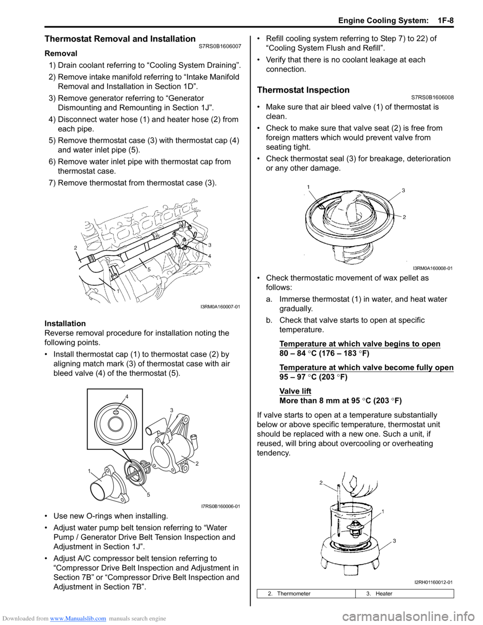
Removal1) Drain coolant referring to “Cooling System Draining”.
2) Remove intake manifold referring to “Intake Manifold Removal and Installa tion in Section 1D”.
3) Remove generator referring to “Generator Dismounting and Remounting in Section 1J”.
4) Disconnect water hose (1) and heater hose (2) from each pipe.
5) Remove thermostat case (3) with thermostat cap (4)
and water inlet pipe (5).
6) Remove water inlet pipe with thermostat cap from thermostat case.
7) Remove thermostat from thermostat case (3).
Installation
Reverse removal procedure for installation noting the
following points.
• Install thermostat cap (1) to thermostat case (2) by aligning match mark (3) of thermostat case with air
bleed valve (4) of the thermostat (5).
• Use new O-rings when installing.
• Adjust water pump belt tension referring to “Water Pump / Generator Drive Belt Tension Inspection and
Adjustment in Section 1J”.
• Adjust A/C compressor belt tension referring to “Compressor Drive Belt Inspection and Adjustment in
Section 7B” or “Compressor Drive Belt Inspection and
Adjustment in Section 7B”. • Refill cooling system referrin
g to Step 7) to 22) of
“Cooling System Flush and Refill”.
• Verify that there is no coolant leakage at each connection.
Thermostat InspectionS7RS0B1606008
• Make sure that air bleed valve (1) of thermostat is clean.
• Check to make sure that va lve seat (2) is free from
foreign matters which would prevent valve from
seating tight.
• Check thermostat seal (3) for breakage, deterioration or any other damage.
• Check thermostatic movement of wax pellet as follows:
a. Immerse thermostat (1) in water, and heat water gradually.
b. Check that valve starts to open at specific temperature.
Temperature at which valve begins to open
80 – 84 °C (176 – 183 °F)
Temperature at which valve become fully open
95 – 97 °C (203 °F)
Va l v e l i ft
More than 8 mm at 95 °C (203 ° F)
If valve starts to open at a temperature substantially
below or above specific temperature, thermostat unit
should be replaced with a new one. Such a unit, if
reused, will bring about ov ercooling or overheating
tendency.
I3RM0A160007-01
4
5 3
1 2
I7RS0B160006-01
2. Thermometer
3. Heater
I3RM0A160008-01
I2RH01160012-01
Page 939 of 1496
Downloaded from www.Manualslib.com manuals search engine Heater and Ventilation: 7A-3
Diagnostic Information and Procedures
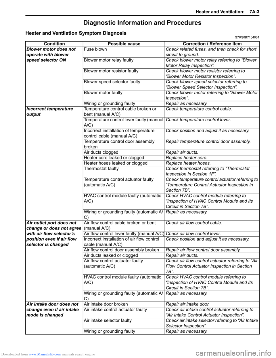
Heater and Ventilation Symptom DiagnosisS7RS0B7104001
ConditionPossible cause Correction / Reference Item
Blower motor does not
operate with blower
speed selector ON Fuse blown
Check related fuses, and then check for short
circuit to ground.
Blower motor relay faulty Check blower motor relay referring to “Blower
Motor Relay Inspection”.
Blower motor resistor faulty Check blower motor resistor referring to
“Blower Motor Resistor Inspection”.
Blower speed selector faulty Check blower speed selector referring to
“Blower Speed Selector Inspection”.
Blower motor faulty Check blower motor referring to “Blower Motor
Inspection”.
Wiring or grounding faulty Repair as necessary.
Incorrect temperature
output Temperature control cable broken or
bent (manual A/C) Check temperature control cable.
Temperature control lever faulty (manual
A/C) Check temperature control lever.
Incorrect installation of temperature
control cable (manual A/C) Check position and adjust it as necessary.
Temperature control door assembly
broken Repair temperature control door assembly.
Air ducts clogged Repair air ducts.
Heater core leaked or clogged Replace heater core.
Heater hoses leaked or clogged Replace heater hoses.
Thermostat faulty Check thermostat referring to “Thermostat
Inspection in Section 1F”.
Temperature control actuator faulty
(automatic A/C) Check temperature control actuator referring to
“Temperature Control Actuator Inspection in
Section 7B”.
HVAC control module faulty (automatic
A/C) Check HVAC control module referring to
“Inspection of HVAC Control Module and Its
Circuit in Section 7B”.
Wiring or grounding faulty (automatic A/
C) Repair as necessary.
Air outlet port does not
change or does not agree
with air flow selector’s
position even if air flow
selector is changed Air flow control cable broken or bent
(manual A/C)
Check air flow control cable.
Air flow control lever faulty (manual A/C) Check air flow control lever.
Incorrect installation of air flow control
cable (manual A/C) Check position and adjust it as necessary.
Air flow control door assembly broken Repair air flow control door assembly.
Air ducts leaked or clogged Repair air ducts.
Air flow control actuator faulty
(automatic A/C) Check air flow control actuator referring to “Air
Flow Control Actuator
Inspection in Section
7B”.
HVAC control module faulty (automatic
A/C) Check HVAC control module referring to
“Inspection of HVAC Control Module and Its
Circuit in Section 7B”.
Wiring or grounding faulty (automatic A/
C) Repair as necessary.
Air intake door does not
change even if air intake
mode is changed Air intake door broken
Repair air intake door.
Air intake control actuator faulty Check air intake control actuator referring to
“Air Intake Control Actuator Inspection”.
Air intake selector faulty Check air intake selector referring to “Air Intake
Selector Inspection”.
Wiring or grounding faulty Repair as necessary.
Page 959 of 1496
Downloaded from www.Manualslib.com manuals search engine Air Conditioning System: Manual Type 7B-11
5) Warm up engine to the normal operating temperature and keep it at the specified idle speed.
6) Turn A/C switch ON, set blower speed selector at maximum speed position, temperature selector at
maximum cold position, airflow selector at face
position, and air intake switch at recirculation
position. (Confirm that A/C compressor and
condenser fans are working.)
7) Wait for ten minutes to stabilize the A/C operation.
8) Open front windows, front doors and engine hood.
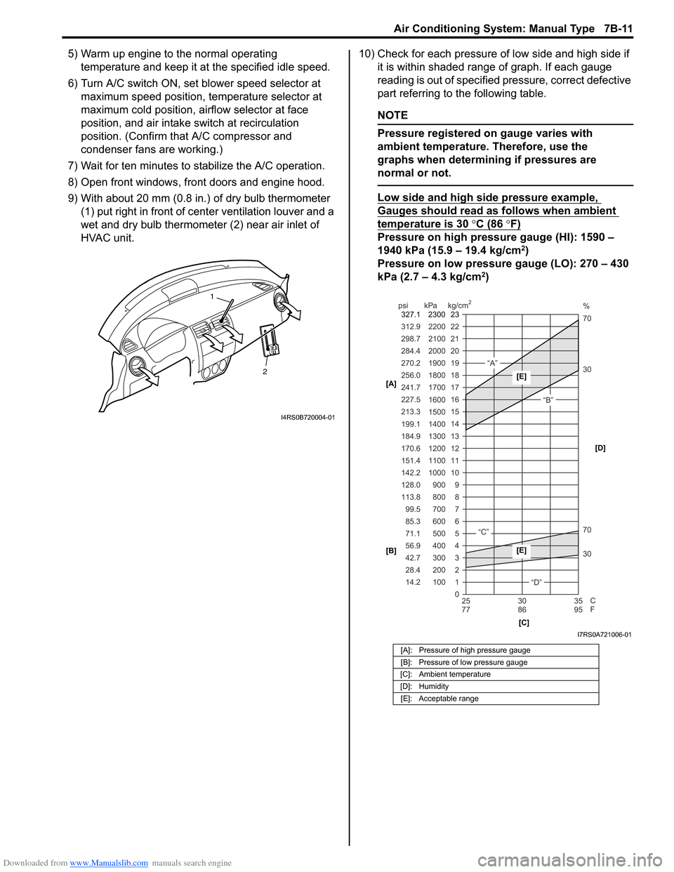
9) With about 20 mm (0.8 in.) of dry bulb thermometer
(1) put right in front of center ventilation louver and a
wet and dry bulb thermometer (2) near air inlet of
HVAC unit. 10) Check for each pressure of low side and high side if
it is within shaded range of graph. If each gauge
reading is out of specified pressure, correct defective
part referring to the following table.
NOTE
Pressure registered on gauge varies with
ambient temperature. Therefore, use the
graphs when determining if pressures are
normal or not.
Low side and high side pressure example,
Gauges should read as follows when ambient
temperature is 30 °C (86 °F)
Pressure on high pressure gauge (HI): 1590 –
1940 kPa (15.9 – 19.4 kg/cm2)
Pressure on low pressure gauge (LO): 270 – 430
kPa (2.7 – 4.3 kg/cm
2)
2
1
I4RS0B720004-01
[A]: Pressure of high pressure gauge
[B]: Pressure of low pressure gauge
[C]: Ambient temperature
[D]: Humidity [E]: Acceptable range
22
312.9 2200
0 1
2 3 30 70 30 70 %
4 5 6 7 8 9
10
11 12 13 14 15
16 17
18
19 21
298.7 2100
20
14.2 28.4 42.7 56.9 71.1 85.3 99.5
113.8 128.0 142.2
151.4
170.6
184.9 199.1
213.3 227.5
241.7
256.0
270.2
284.4
100 200 300 400 500 600 700 800 900
1000 1100 1200
1300
1400 1500 1600
1700 1800
1900
2000
25 30 35
77 86 95
psi kPa kg/cm
2
C
F
“A”
“B”
“C”
“D”
23
2300
327.1
[A]
[B]
[C][D][E]
[E]
I7RS0A721006-01
Page 961 of 1496
Downloaded from www.Manualslib.com manuals search engine Air Conditioning System: Manual Type 7B-13
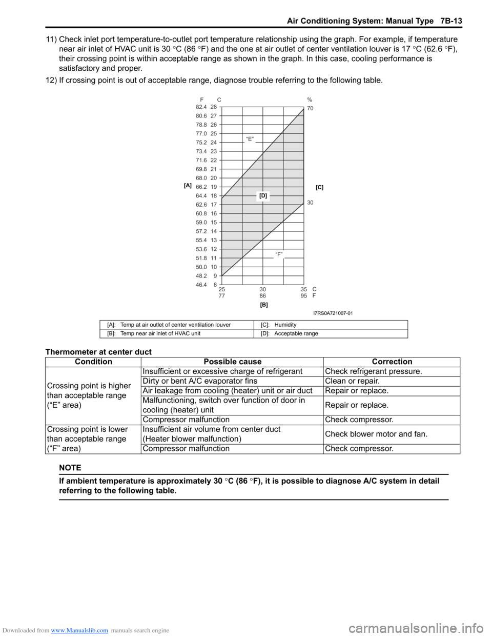
11) Check inlet port temperature-to-outlet port temperature relationship using the graph. For example, if temperature
near air inlet of HVAC unit is 30 °C (86 °F) and the one at air outlet of center ventilation louver is 17 °C (62.6 °F),
their crossing point is within acceptable range as shown in the graph. In this case, cooling performance is
satisfactory and proper.
12) If crossing point is out of acceptable range, diagnose trouble referring to the following table.
Thermometer at center duct
NOTE
If ambient temperature is approximately 30 °C (86 °F), it is possible to diagnose A/C system in detail
referring to the following table.
[A]: Temp at air outlet of center ventilation louver [C]: Humidity
[B]: Temp near air inlet of HVAC unit [D]: Acceptable range
ConditionPossible cause Correction
Crossing point is higher
than acceptable range
(“E” area) Insufficient or excessive charge of refrigerant Check refrigerant pressure.
Dirty or bent A/C evaporator fins
Clean or repair.
Air leakage from cooling (heater) unit or air duct Repair or replace.
Malfunctioning, switch over function of door in
cooling (heater) unit Repair or replace.
Compressor malfunct ion Check compressor.
Crossing point is lower
than acceptable range
(“F” area) Insufficient air volume from center duct
(Heater blower malfunction)
Check blower motor and fan.
Compressor malfunct ion Check compressor.
8 9
10 11 12 13 14
15 16 17 18 19
20
21
22
23
24
25 26
27
28
46.4 48.2 50.0 51.8 53.6 55.4 57.2 59.0 60.8 62.6 64.4
66.2 68.0
69.8
71.6
73.4
75.2
77.0
78.8 80.6
82.4
25 30 35
77 86 95
F C
C
F
“E”
“F”30 70 %
[A]
[B][C]
[D]
I7RS0A721007-01
Page 1306 of 1496
Downloaded from www.Manualslib.com manuals search engine 9C-11 Instrumentation / Driver Info. / Horn:
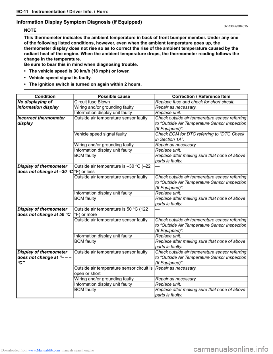
Information Display Symptom Diagnosis (If Equipped)S7RS0B9304015
NOTE
This thermometer indicates the ambient temperature in back of front bumper member. Under any one
of the following listed conditions, however, even when the ambient temperature goes up, the
thermometer display does not rise so as to correct the rise of the ambient temperature caused by the
radiant heat of the engine. When the ambient temperature drops, the thermometer reading follows the
change in the temperature.
Be sure to bear this in mind when diagnosing trouble.
• The vehicle speed is 30 km/h (18 mph) or lower.
• Vehicle speed signal is faulty.
• The ignition switch is turned on again within 2 hours.
ConditionPossible cause Correction / Reference Item
No displaying of
information display Circuit fuse Blown
Replace fuse and check for short circuit.
Wiring and/or grounding faulty Repair as necessary.
Information display unit faulty Replace unit.
Incorrect thermometer
display Outside air temperature sensor faulty
Check outside air temperature sensor referring
to “Outside Air Temperature Sensor Inspection
(If Equipped)”.
Vehicle speed signal faulty Check ECM for DTC referring to “DTC Check
in Section 1A”.
Wiring and/or grounding faulty Repair as necessary.
Information display unit faulty Replace unit.
BCM faulty Replace after making sure that none of above
parts is faulty.
Display of thermometer
does not change at –30
°C Outside air temperature is –30
°C (–22
° F) or less —
Outside air temperature sensor faulty Check outside air temperature sensor referring
to “Outside Air Temperature Sensor Inspection
(If Equipped)”.
Information display unit faulty Replace unit.
BCM faulty Replace after making sure that none of above
parts is faulty.
Display of thermometer
does not change at 50
°C Outside air temperature is 50
°C (122
° F) or more —
Outside air temperature sensor faulty Check outside air temperature sensor referring
to “Outside Air Temperature Sensor Inspection
(If Equipped)”.
Information display unit faulty Replace unit.
BCM faulty Replace after making sure that none of above
parts is faulty.
Display of thermometer
does not change at “– – –
°C” Outside air temperature sensor faulty
Check outside air temperature sensor referring
to “Outside Air Temperature Sensor Inspection
(If Equipped)”.
Outside air temperature sensor circuit is
open or short Repair as necessary.
Wiring and/or grounding faulty Repair as necessary.
Information display unit faulty Replace unit.
BCM faulty Replace after making sure that none of above
parts is faulty.
Page 1466 of 1496
Downloaded from www.Manualslib.com manuals search engine 10E-4 Keyless Start System:
Door Lock Function of Keyless Start SystemS7RS0BA501004
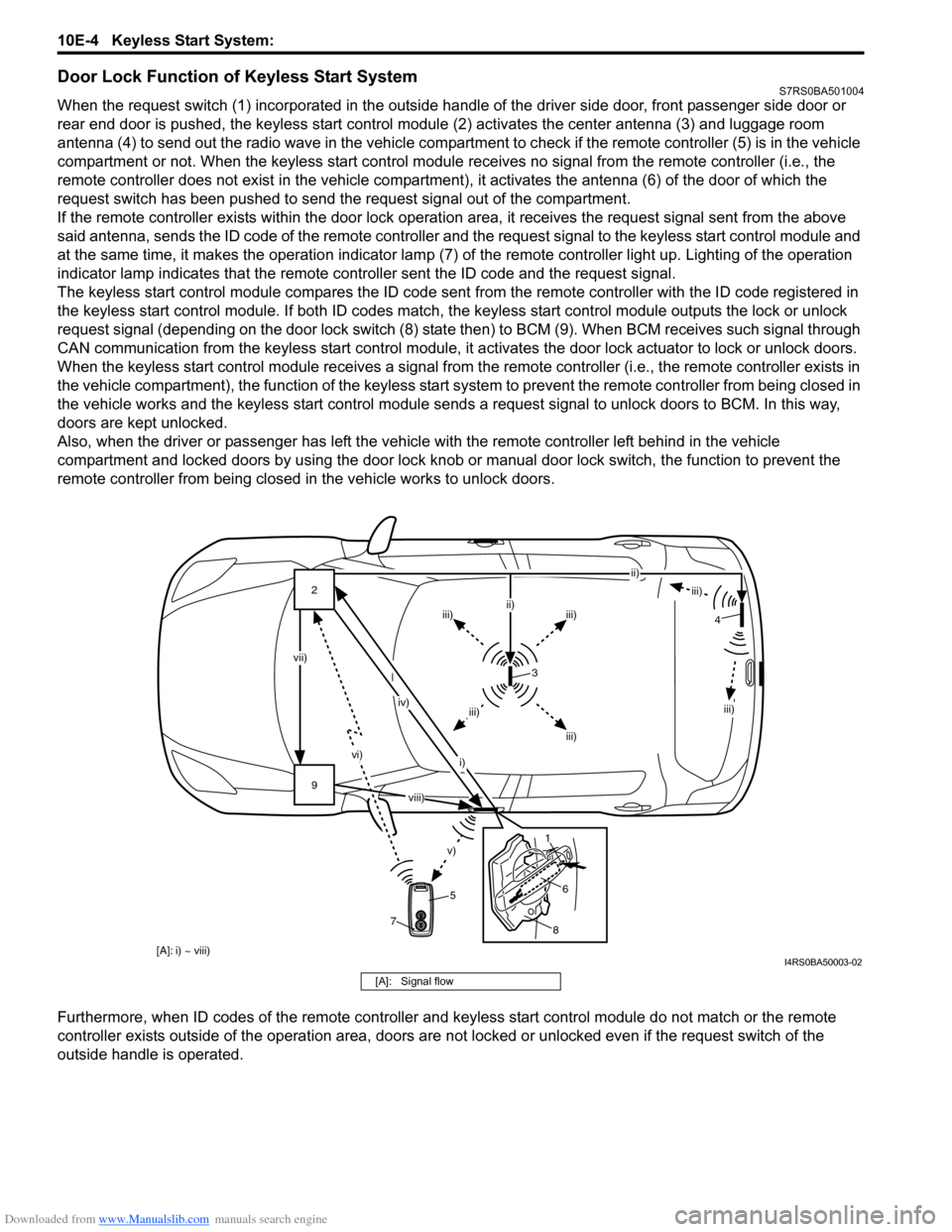
When the request switch (1) incorporated in the outside handle of the driver side door, front passenger side door or
rear end door is pushed, the keyless start control modul e (2) activates the center antenna (3) and luggage room
antenna (4) to send out the radio wave in the vehicle compartm ent to check if the remote controller (5) is in the vehicle
compartment or not. When the keyless start control module receives no signal from the remote controller (i.e., the
remote controller does not exist in the vehicle compartment) , it activates the antenna (6) of the door of which the
request switch has been pushed to send the request signal out of the compartment.
If the remote controller exists within the door lock operati on area, it receives the request signal sent from the above
said antenna, sends the ID code of the remote controller and the request signal to the keyless start control module and
at the same time, it makes the operatio n indicator lamp (7) of the remote controller light up. Lighting of the operation
indicator lamp indicates that the remote controller sent the ID code and the request signal.
The keyless start control module compares the ID code sent from the remote controller with the ID code registered in
the keyless start control module. If both ID codes match, the keyless start control module outputs the lock or unlock
request signal (depending on the door lock switch (8) stat e then) to BCM (9). When BCM receives such signal through
CAN communication from the keyless start control module, it activates the door lock actuator to lock or unlock doors.
When the keyless start control module receiv es a signal from the remote controller (i.e., the remote controller exists in
the vehicle compartment), the function of the keyless start system to prevent the remote controller from being closed in
the vehicle works and the keyless start control module sends a request signal to unlock doors to BCM. In this way,
doors are kept unlocked.
Also, when the driver or passenger has left the vehicl e with the remote controller left behind in the vehicle
compartment and locked doors by using the door lock knob or manual door lock switch, the function to prevent the
remote controller from being closed in the vehicle works to unlock doors.
Furthermore, when ID codes of the remote controller and keyless start control module do not match or the remote
controller exists outside of the operation area, doors are not locked or unlocked even if the request switch of the
outside handle is operated.
9 2
vi)
v)
vii) iv)
i) ii)
iii)
iii)iii)
ii)
iii)
iii)
iii)
3
5
8
6
1 4
7
[A]: i) ~ viii)
viii)
I4RS0BA50003-02
[A]: Signal flow