glove box SUZUKI SWIFT 2004 2.G Service User Guide
[x] Cancel search | Manufacturer: SUZUKI, Model Year: 2004, Model line: SWIFT, Model: SUZUKI SWIFT 2004 2.GPages: 1496, PDF Size: 34.44 MB
Page 1093 of 1496
Downloaded from www.Manualslib.com manuals search engine Air Bag System: 8B-55
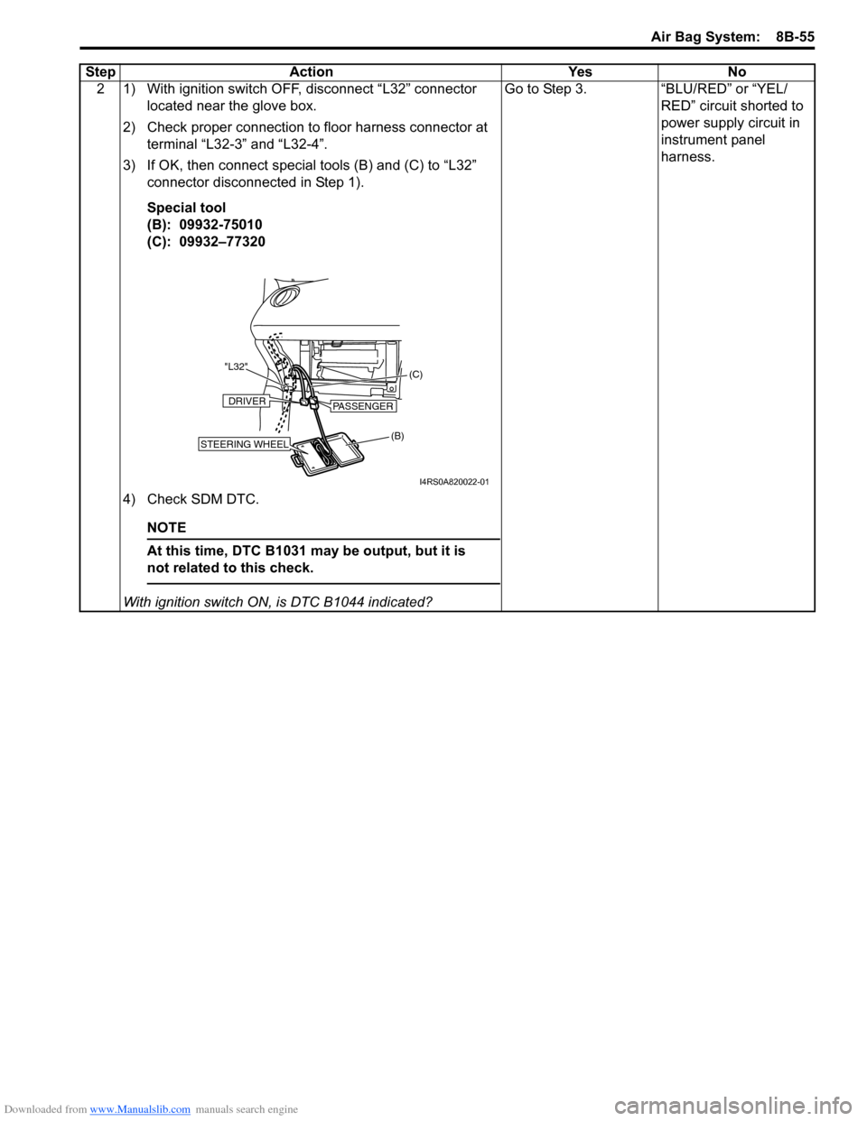
2 1) With ignition switch OFF, disconnect “L32” connector located near the glove box.
2) Check proper connection to floor harness connector at terminal “L32-3” and “L32-4”.
3) If OK, then connect special tools (B) and (C) to “L32” connector disconnected in Step 1).
Special tool
(B): 09932-75010
(C): 09932–77320
4) Check SDM DTC.
NOTE
At this time, DTC B1031 ma y be output, but it is
not related to this check.
With ignition switch ON , is DTC B1044 indicated? Go to Step 3. “BLU/RED” or “YEL/
RED” circuit shorted to
power supply circuit in
instrument panel
harness.
Step Action Yes No
(B) (C)
"L32"STEERING WHEEL
DRIVERPASSENGER
I4RS0A820022-01
Page 1136 of 1496
Downloaded from www.Manualslib.com manuals search engine 8B-98 Air Bag System:
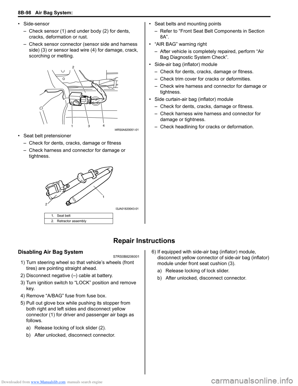
• Side-sensor– Check sensor (1) and under body (2) for dents, cracks, deformation or rust.
– Check sensor connector (sensor side and harness side) (3) or sensor lead wire (4) for damage, crack,
scorching or melting.
• Seat belt pretensioner – Check for dents, cracks , damage or fitness
– Check harness and connector for damage or tightness. • Seat belts and mounting points
– Refer to “Front Seat Belt Components in Section 8A”.
• “AIR BAG” warning right
– After vehicle is completely repaired, perform “Air Bag Diagnostic System Check”.
• Side-air bag (inflator) module – Check for dents, cra cks, damage or fitness.
– Check trim cover for cracks or deformities.
– Check wire harness and connector for damage or tightness.
• Side curtain-air bag (inflator) module – Check for dents, cra cks, damage or fitness.
– Check harness wire harness and connector for damage or tightness.
– Check headlining for cracks or deformation.
Repair Instructions
Disabling Air Bag SystemS7RS0B8206001
1) Turn steering wheel so that vehicle’s wheels (front tires) are pointing straight ahead.
2) Disconnect negative (–) cable at battery.
3) Turn ignition switch to “LOCK” position and remove key.
4) Remove “A/BAG” fu se from fuse box.
5) Pull out glove box while pushing its stopper from
both right and left sides and disconnect yellow
connector (1) for driver and passenger air bags as
follows.
a) Release locking of lock slider (2).
b) After unlocked, disconnect connector. 6) If equipped with side-air bag (inflator) module,
disconnect yellow connector of side-air bag (inflator)
module under front seat cushion (3).
a) Release locking of lock slider.
b) After unlocked, disconnect connector.
1. Seat belt
2. Retractor assembly
13 4
2I4RS0A820051-01
I3JA01820043-01
Page 1137 of 1496
Downloaded from www.Manualslib.com manuals search engine Air Bag System: 8B-99
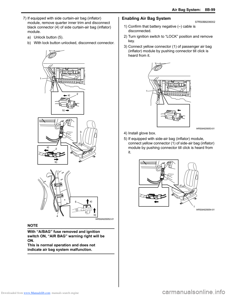
7) If equipped with side curtain-air bag (inflator) module, remove quarter inner trim and disconnect
black connector (4) of side curtain-air bag (inflator)
module.
a) Unlock button (5).
b) With lock button unlocked, disconnect connector.
NOTE
With “A/BAG” fuse removed and ignition
switch ON, “AIR BAG” warning right will be
ON.
This is normal operation and does not
indicate air bag system malfunction.
Enabling Air Bag SystemS7RS0B8206002
1) Confirm that battery negative (–) cable is disconnected.
2) Turn ignition switch to “LOCK” position and remove key.
3) Connect yellow connector (1) of passenger air bag (inflator) module by push ing connector till click is
heard from it.
4) Install glove box.
5) If equipped with side-air bag (inflator) module, connect yellow connector (1) of side-air bag (inflator)
module by pushing connector till click is heard from
it.
a)
b)2
3
2a)
b)
1
5
4 a)
b)
I4RS0A820052-01
1
I4RS0A820053-01
1I4RS0A820054-01
Page 1150 of 1496

Downloaded from www.Manualslib.com manuals search engine 8B-112 Air Bag System:
• Check sensor (1) for dents, crack, deformation.
• Check sensor connector (sensor side and harness side), lock mechanism or sensor lead wire for
damage, crack, scorching or melting.
• Check connector terminals for bent, corrosion or rust. If any faulty condition is found in above checks,
replace.
Passenger Air Bag (Inflator) Module Repair
Harness Installation
S7RS0B8206017
Replace passenger air bag (inflator) module repair
harness (4) according to the following procedure when
the harness (1) connect ed with passenger air bag
(inflator) module of the air bag harness included in
instrument panel harness (2) and passenger air bag
(inflator) module connector (3) is damaged. 1) Disable air bag system. Re
fer to “Disabling Air Bag
System”.
2) Disconnect “L32” connector from floor harness located near the glove box.
3) Cut off passenger air bag (inflator) module harness (1) included in instrument panel harness (2) as
shown, and then fasten it to instrument panel
harness with vinyl tape for avoiding interference with
other parts.
4) Install passenger air bag (inflator) module repair harness (1) to floor harness (2), instrument panel
harness (3) and passenger air bag (inflator) module.CAUTION!
To avoid interference with other parts, fasten
the repair harness to in strument wire harness
with a clamp or vinyl tape as shown in figure.
5) Connect each connector securely till click is heard.
5. Driver air bag (inflator) module 7. Floor harness
6. Passenger air bag (inflator) module 8. Vinyl tape
1I4RS0A820082-01
7
4
6
6
2
28
1
3
5
5
7I4RS0A820103-01
1
I4RS0A820083-01
1
2
3
I4RS0A820085-01
Page 1159 of 1496
Downloaded from www.Manualslib.com manuals search engine Air Bag System: 8B-121
Deployment / Activation Inside of Vehicle
When the vehicle will be destroyed, or salvaged for
component parts, deploy the air bag modules and/or
activate seat belt pretensioners installed on vehicle.
NOTE
If equipped with the seat belt pretensioners,
activate both side of seat belt pretensioners
at the same time when using special tool (C).
1) Turn ignition switch to LOCK position, remove key
and put on safety glasses.
2) Remove all loose objects from front seats and instrument panel.
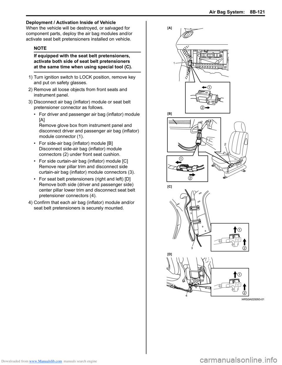
3) Disconnect air bag (inflator) module or seat belt pretensioner connector as follows.
• For driver and passenger air bag (inflator) module [A]
Remove glove box from instrument panel and
disconnect driver and passenger air bag (inflator)
module connector (1).
• For side-air bag (inflator) module [B] Disconnect side-air bag (inflator) module
connectors (2) under front seat cushion.
• For side curtain-air bag (inflator) module [C] Remove rear pillar trim and disconnect side
curtain-air bag (inflator) module connectors (3).
• For seat belt pretensioners (right and left) [D] Remove both side (driver and passenger side)
center pillar lower trim an d disconnect seat belt
pretensioner connectors (4).
4) Confirm that each air bag (inflator) module and/or seat belt pretensioners is securely mounted.
[A]
[B]
[C]
[D]
2
1
3
4
1
2
1
2
1
2
1
2
I4RS0A820093-01
Page 1313 of 1496
Downloaded from www.Manualslib.com manuals search engine Instrumentation / Driver Info. / Horn: 9C-18
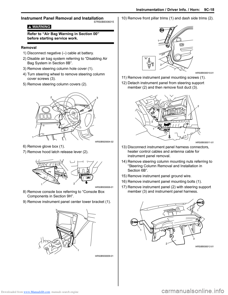
Instrument Panel Removal and InstallationS7RS0B9306015
WARNING!
Refer to “Air Bag Warning in Section 00”
before starting service work.
Removal
1) Disconnect negative (–) cable at battery.
2) Disable air bag system referring to “Disabling Air Bag System in Section 8B”.
3) Remove steering column hole cover (1).
4) Turn steering wheel to remove steering column cover screws (3).
5) Remove steering column covers (2).
6) Remove glove box (1).
7) Remove hood latch release lever (2).
8) Remove console box referring to “Console Box Components in Section 9H”.
9) Remove instrument panel center lower bracket (1). 10) Remove front pillar trims
(1) and dash side trims (2).
11) Remove instrument panel mounting screws (1).
12) Detach instrument panel from steering support member (2) and then remove foot duct (3).
13) Disconnect instrument panel harness connectors, heater control cables and antenna cable for
instrument panel removal.
14) Remove steering column mounting nuts referring to “Steering Column Remova l and Installation in
Section 6B”.
15) Remove instrument panel ground wire.
16) Remove instrument panel mounting bolts (1).
17) Remove instrument panel (2) with steering support member (3) and instrument panel harness.
1
32
I4RS0B920004-02
2
1I4RS0B930008-01
1
I4RS0B930009-01
“A”
“A”
1
2
I4RS0B930010-01
1
1 2
3
I4RS0B930011-01
1 1
2
3I4RS0B930012-01
Page 1467 of 1496
Downloaded from www.Manualslib.com manuals search engine Keyless Start System: 10E-5
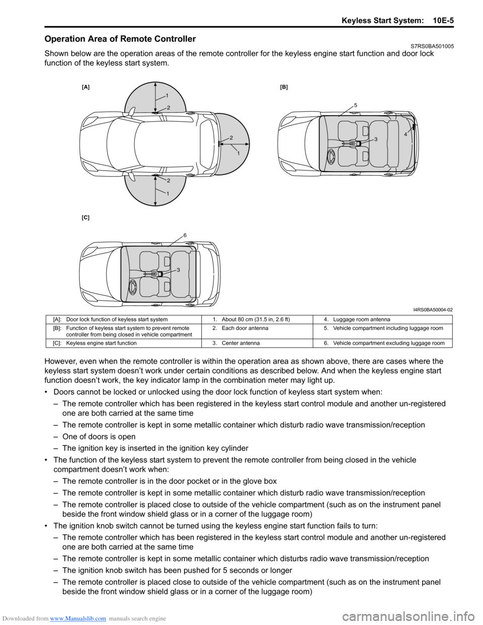
Operation Area of Remote ControllerS7RS0BA501005
Shown below are the operation areas of the remote controller for the keyless engine start function and door lock
function of the keyless start system.
However, even when the remote controller is within the operation area as shown above, there are cases where the
keyless start system doesn’t work under certain conditi ons as described below. And when the keyless engine start
function doesn’t work, the key indicator la mp in the combination meter may light up.
• Doors cannot be locked or unlocked using the doo r lock function of keyless start system when:
– The remote controller which has been registered in the keyless start control module and another un-registered one are both carried at the same time
– The remote controller is kept in some metallic co ntainer which disturb radio wave transmission/reception
– One of doors is open
– The ignition key is inserted in the ignition key cylinder
• The function of the keyless start system to prevent the remote controller from being closed in the vehicle
compartment doesn’t work when:
– The remote controller is in the door pocket or in the glove box
– The remote controller is kept in some metallic co ntainer which disturb radio wave transmission/reception
– The remote controller is placed close to outside of the vehicle compartment (such as on the instrument panel beside the front window shield glass or in a corner of the luggage room)
• The ignition knob switch cannot be turned usin g the keyless engine start function fails to turn:
– The remote controller which has been registered in the keyless start control module and another un-registered one are both carried at the same time
– The remote controller is kept in some metallic cont ainer which disturbs radio wave transmission/reception
– The ignition knob switch has been pushed for 5 seconds or longer
– The remote controller is placed close to outside of the vehicle compartment (such as on the instrument panel beside the front window shield glass or in a corner of the luggage room)
[A] [B]
[C]
1
1
1
25
6
3
3 4
2
2
I4RS0BA50004-02
[A]: Door lock function of keyless start system 1. About 80 cm (31.5 in, 2.6 ft)4. Luggage room antenna
[B]: Function of keyless start system to prevent remote controller from being closed in vehicle compartment 2. Each door antenna
5. Vehicle compartment including luggage room
[C]: Keyless engine start function 3. Center antenna6. Vehicle compartment excluding luggage room
Page 1494 of 1496
Downloaded from www.Manualslib.com manuals search engine 10E-32 Keyless Start System:
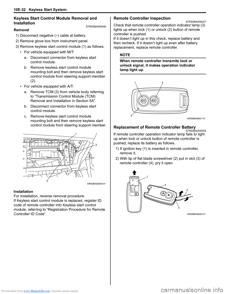
Keyless Start Control Module Removal and
Installation
S7RS0BA506006
Removal1) Disconnect negative (–) cable at battery.
2) Remove glove box from instrument panel.
3) Remove keyless start cont rol module (1) as follows.
• For vehicle equipped with M/T:
a. Disconnect connector from keyless start control module.
b. Remove keyless start control module mounting bolt and then remove keyless start
control module from steering support member
(2).
• For vehicle equipped with A/T: a. Remove TCM (3) from vehicle body referring to “Transmission Control Module (TCM)
Removal and Installation in Section 5A”.
b. Disconnect connector from keyless start control module.
c. Remove keyless start control module mounting bolt and then remove keyless start
control module from steering support member.
Installation
For installation, reverse removal procedure.
If Keyless start control module is replaced, register ID
code of remote controller in to Keyless start control
module, referring to “Registration Procedure for Remote
Controller ID Code”.
Remote Controller InspectionS7RS0BA506007
Check that remote controller operation indicator lamp (3)
lights up when lock (1) or un lock (2) button of remote
controller is pushed.
If it doesn’t light up in this check, replace battery and
then recheck. If it doesn’t light up even after battery
replacement, replace remote controller.
NOTE
When remote controller transmits lock or
unlock signal, it makes operation indicator
lamp light up.
Replacement of Remote Controller BatteryS7RS0BA506008
If remote controller operation i ndicator lamp fails to light
up when lock or unlock button of remote controller is
pushed, replace its battery as follows.
1) If ignition key (1) is inse rted in remote controller,
remove it.
2) With tip of flat blade screwdriver (2) put in slot (3) of remote controller (4), pry it open.1
3
2
I4RS0BA50030-01
12
3I4RS0BA50031-01
1
4
2
3
I4RS0BA50032-01