change battery SUZUKI SWIFT 2004 2.G Service Workshop Manual
[x] Cancel search | Manufacturer: SUZUKI, Model Year: 2004, Model line: SWIFT, Model: SUZUKI SWIFT 2004 2.GPages: 1496, PDF Size: 34.44 MB
Page 33 of 1496
Downloaded from www.Manualslib.com manuals search engine Maintenance and Lubrication: 0B-3
NOTE
тАв тАЬIтАЭ: Inspect and correct or replace if necessary
тАв тАЬRтАЭ: Replace or change
тАв *1: Inspect or replace more frequently if the vehicle is used under dusty conditions.
тАв *2: Clean or replace more frequently if the air from the air conditioning decreases.
Repair Instructions
Accessory Drive Belt InspectionS7RS0B0206001
WARNING!
All inspection and replacement are to be
performed with ENGINE NOT RUNNING.
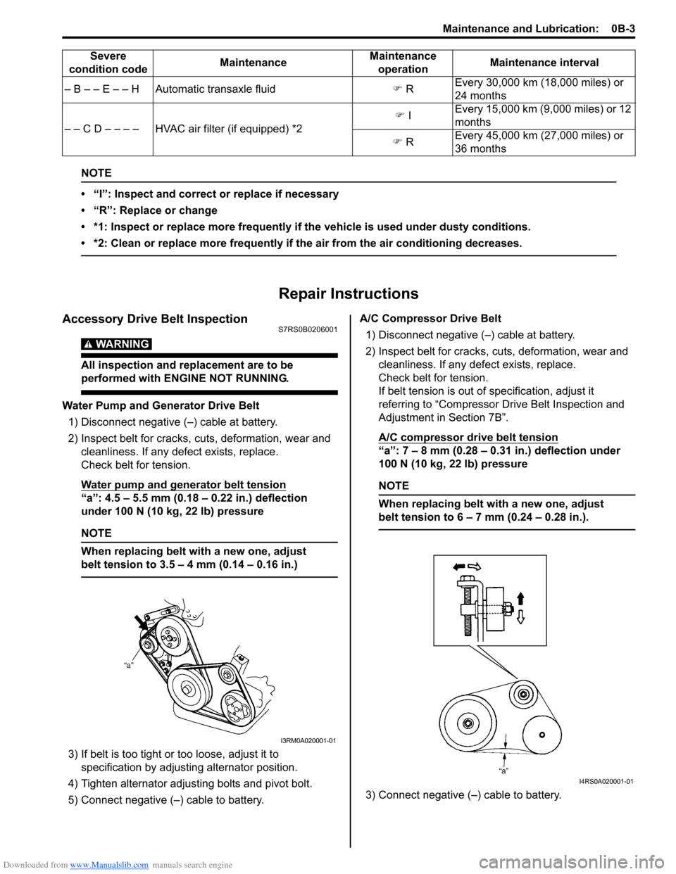
Water Pump and Generator Drive Belt1) Disconnect negative (тАУ) cable at battery.
2) Inspect belt for cracks, cu ts, deformation, wear and
cleanliness. If any defect exists, replace.
Check belt for tension.
Water pump and generator belt tension
тАЬaтАЭ: 4.5 тАУ 5.5 mm (0.18 тАУ 0.22 in.) deflection
under 100 N (10 kg, 22 lb) pressure
NOTE
When replacing belt with a new one, adjust
belt tension to 3.5 тАУ 4 mm (0.14 тАУ 0.16 in.)
3) If belt is too tight or too loose, adjust it to
specification by adjusting alternator position.
4) Tighten alternator adjusting bolts and pivot bolt.
5) Connect negative (тАУ) cable to battery. A/C Compressor Drive Belt
1) Disconnect negative (тАУ) cable at battery.
2) Inspect belt for cracks, cuts, deformation, wear and cleanliness. If any defect exists, replace.
Check belt for tension.
If belt tension is out of specification, adjust it
referring to тАЬCompressor Dr ive Belt Inspection and
Adjustment in Section 7BтАЭ.
A/C compressor drive belt tension
тАЬaтАЭ: 7 тАУ 8 mm (0.28 тАУ 0.31 in.) deflection under
100 N (10 kg, 22 lb) pressure
NOTE
When replacing belt with a new one, adjust
belt tension to 6 тАУ 7 mm (0.24 тАУ 0.28 in.).
3) Connect negative (тАУ) cable to battery.
тАУ B тАУ тАУ E тАУ тАУ H Automatic transaxle fluid
�) R Every 30,000 km (18,000 miles) or
24 months
тАУ тАУ C D тАУ тАУ тАУ тАУ HVAC air filter (if equipped) *2 �)
I Every 15,000 km (9,000 miles) or 12
months
�) R Every 45,000 km (27,000 miles) or
36 months
Severe
condition code MaintenanceMaintenance
operation Maintenance interval
I3RM0A020001-01
I4RS0A020001-01
Page 61 of 1496
Downloaded from www.Manualslib.com manuals search engine Engine General Information and Diagnosis: 1A-11
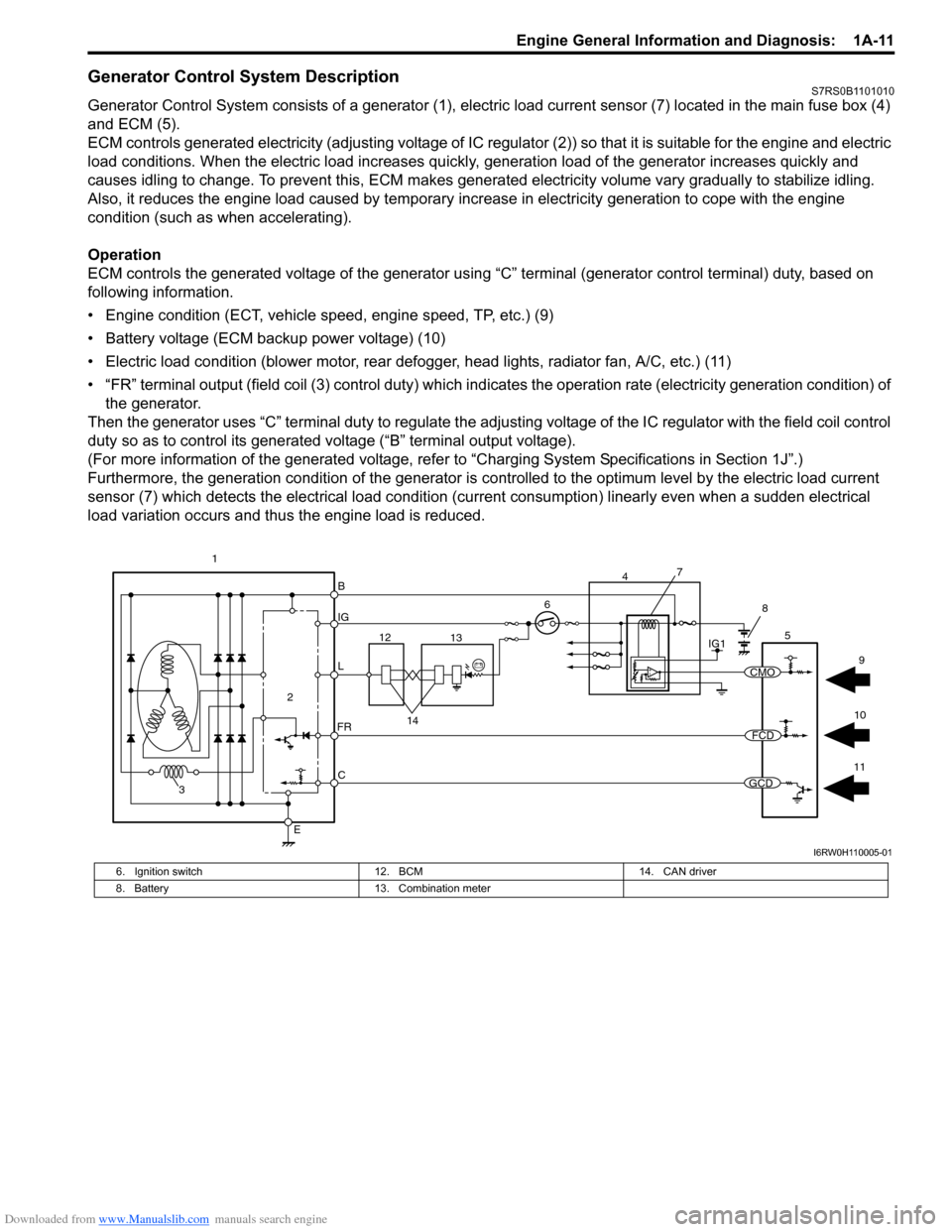
Generator Control System DescriptionS7RS0B1101010
Generator Control System consists of a generator (1), electric load current sensor (7) located in the main fuse box (4)
and ECM (5).
ECM controls generated electricity (adjusting voltage of IC regulator (2)) so that it is suitable for the engine and electric
load conditions. When the electric load increases quickly, generation load of the generator increases quickly and
causes idling to change. To prevent this, ECM makes generated electricity volume vary gradually to stabilize idling.
Also, it reduces the engine load caused by temporary incr ease in electricity generation to cope with the engine
condition (such as when accelerating).
Operation
ECM controls the generated voltage of the generator using тАЬCтАЭ terminal (generator control terminal) duty, based on
following information.
тАв Engine condition (ECT, vehicle speed, engine speed, TP, etc.) (9)
тАв Battery voltage (ECM backup power voltage) (10)
тАв Electric load condition (blower motor, rear defogger, head lights, radiator fan, A/C, etc.) (11)
тАв тАЬFRтАЭ terminal output (field coil (3) cont rol duty) which indicates the operation rate (electricity generation condition) of
the generator.
Then the generator uses тАЬCтАЭ terminal duty to regulate the adju sting voltage of the IC regulator with the field coil control
duty so as to control its generated voltage (тАЬBтАЭ terminal output voltage).
(For more information of the generated voltage, refer to тАЬCharging System Specifications in Section 1JтАЭ.)
Furthermore, the generation condition of the generator is co ntrolled to the optimum level by the electric load current
sensor (7) which detects the electrical load condition (cur rent consumption) linearly even when a sudden electrical
load variation occurs and thus the engine load is reduced.
B
IG
L
C
E
6
2
3
FR
5
12 13
14
1IG1
7
4
8
11
10 9
CMO
FCD
GCD
I6RW0H110005-01
6. Ignition switch
12. BCM 14. CAN driver
8. Battery 13. Combination meter
Page 87 of 1496
Downloaded from www.Manualslib.com manuals search engine Engine General Information and Diagnosis: 1A-37
TP SENSOR 2 VOLT (THROTTLE POSITION SENSOR
(SUB) OUTPUT VOLTAGE, V)
The TP sensor (sub) reading provides throttle valve
opening information in the form of voltage.
APP SENSOR 1 VOLT (ACCELERATOR PEDAL
POSITION (APP) SENSOR (MAIN) OUTPUT
VOLTAGE, V)
The APP sensor (main) read ing provides accelerator
pedal opening information in the form of voltage.
APP SENSOR 2 VOLT (ACCELERATOR PEDAL
POSITION (APP) SENSOR (S UB) OUTPUT VOLTAGE,
V)
The APP sensor (sub) reading provides accelerator
pedal opening information in the form of voltage.
ACCEL POSITION (ABSOLUTE ACCELERATOR
PEDAL POSITION, %)
When accelerator pedal is at fully released position,
accelerator pedal is indicated as 0 тАУ 5% and 90 тАУ 100%
fully depressed position. THROTTLE TARGET POSI (TARGET THROTTLE
VALVE POSITION, %)
Target throttle valve position is ECM internal parameter
which indicates the ECM requested throttle valve
position.
BATTERY CURRENT (A)
This parameter indicates elec
tric load value (current
consumption) that detected by electric load current
sensor.
GENERATOR CONT DUTY (GENERATOR CONTROL
DUTY, %)
This parameter indicates generator control duty ratio that
controls production electricity of generator by ECM.
100%: No limitation for the generating
0%: Maximum limitation for the generating
GENERATOR FIELD DUTY (GENERATOR FIELD
COIL DUTY, %)
This parameter indicates ope rating rate (status of
production electricity) for gen erator by field coil duty
ratio.
100%: maximum operation.
0%: minimum operation.
Visual InspectionS7RS0B1104008
Visually check the following parts and systems.
Inspection item Reference section
тАв Engine oil тАУ level, leakage тАЬEngine Oil and Filter Change in Section 0BтАЭ
тАв Engine coolant тАУ level, leakage тАЬCo olant Level Check in Section 1FтАЭ
тАв Fuel тАУ level, leakage тАЬFuel Lines and Connections Inspection in Section 0BтАЭ
тАв Air cleaner element тАУ dirt, clogging тАЬAir Cleaner Filter Inspection in Section 0BтАЭ
тАв Battery тАУ fluid level, corrosion of terminal тАЬBattery Description in Section 1JтАЭ
тАв Water pump belt тАУ tension damage тАЬAccessory Drive Belt Inspection in Section 0BтАЭ
тАв Throttle valve тАУ operating sound тАЬElectric Throttle Body Assembly On-Vehicle Inspection in Section 1CтАЭ
тАв Vacuum hoses of air intake system тАУ disconnection, looseness,
deterioration, bend тАЬVacuum Hose and Purge Valve Chamber
Inspection in Section 1BтАЭ
тАв Connectors of electric wire harness тАУ disconnection, friction
тАв Fuses тАУ burning
тАв Parts тАУ installation, bolt тАУ looseness
тАв Parts тАУ deformation
тАв Other parts that can be checked visually
Also check the following items at engine start, if possible
тАв Malfunction indicator lamp тАУ Operation тАЬMalfunction Indicator Lamp (MIL) CheckтАЭ
тАв Charge warning lamp тАУ Operation тАЬGenera tor Symptom Diagnosis in Section 1JтАЭ
тАв Engine oil pressure warning lamp тАУ Operation тАЬO il Pressure Switch Inspection in Section 9CтАЭ
тАв Engine coolant temp. meter тАУ Operation тАЬECT Sensor Inspection in Section 1CтАЭ
тАв Fuel level meter тАУ Operation тАЬFuel Level Sensor Inspection in Section 9CтАЭ
тАв Tachometer тАУ Operation
тАв Abnormal air being inhaled from air intake system
тАв Exhaust system тАУ leakage of exhaust gas, noise
тАв Other parts that can be checked visually
Page 305 of 1496
Downloaded from www.Manualslib.com manuals search engine Engine Mechanical: 1D-20
15) Install A/C compressor to its bracket (if equipped) referring to тАЬCompressor Assembly Removal and
Installation in Section 7BтАЭ or тАЬCompressor Assembly
Removal and Installa tion in Section 7BтАЭ.
16) Adjust A/C compressor belt tension (if equipped) referring to тАЬCompressor Drive Belt Inspection and
Adjustment in Section 7BтАЭ or тАЬCompressor Drive Belt
Inspection and Adjustment in Section 7BтАЭ.
17) Check to ensure that a ll removed parts are back in
place.
Reinstall any necessary parts which have not been
reinstalled.
18) Refill cooling system with coolant referring to тАЬCooling System Flush and Refill in Section 1FтАЭ. 19) Refill engine with engine oil
referring to тАЬEngine Oil
and Filter Change in Section 0BтАЭ.
20) Refill transaxle with transa xle oil referring toтАЬManual
Transaxle Oil Change in Section 5BтАЭ or тАЬA/T Fluid
Change in Section 5AтАЭ.
21) Install battery and tray.
22) Connect positive and negative cable at battery.
23) Install engine hood and connect windshield washer hose.
24) Verify that there is no fu el leakage, coolant leakage,
oil leakage and exhaust gas leakage at each
connection.
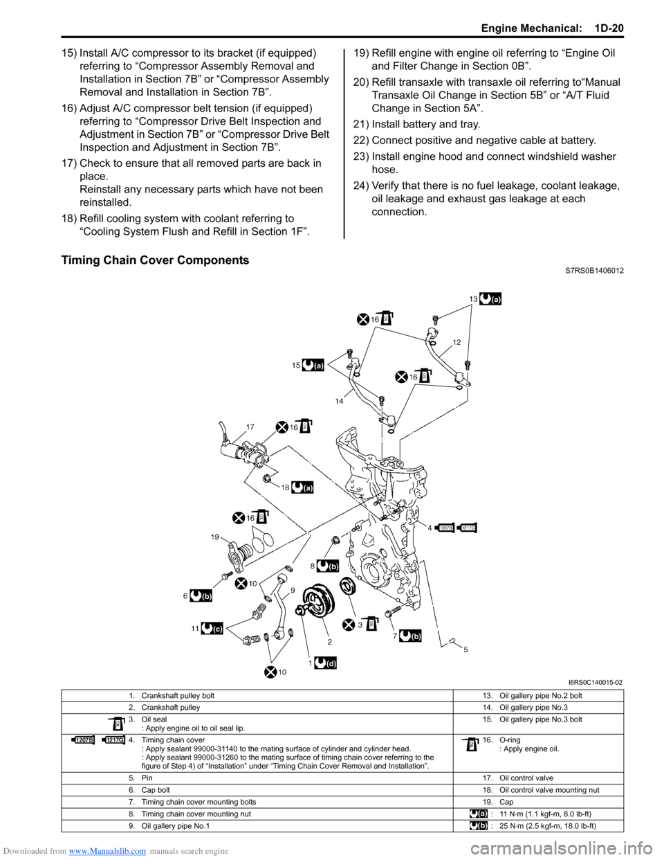
Timing Chain Cover ComponentsS7RS0B1406012
I6RS0C140015-02
1. Crankshaft pulley bolt 13. Oil gallery pipe No.2 bolt
2. Crankshaft pulley 14. Oil gallery pipe No.3
3. Oil seal : Apply engine oil to oil seal lip. 15. Oil gallery pipe No.3 bolt
4. Timing chain cover : Apply sealant 99000-31140 to the mating surface of cylinder and cylinder head.
: Apply sealant 99000-31260 to the mating surface of timing chain cover referring to the
figure of Step 4) of тАЬInstallationтАЭ under тАЬTiming Chain Cover Removal and InstallationтАЭ. 16. O-ring
: Apply engine oil.
5. Pin 17. Oil control valve
6. Cap bolt 18. Oil control valve mounting nut
7. Timing chain cover mounting bolts 19. Cap
8. Timing chain cover mounting nut : 11 N тЛЕm (1.1 kgf-m, 8.0 lb-ft)
9. Oil gallery pipe No.1 :25 NтЛЕm (2.5 kgf-m, 18.0 lb-ft)
Page 373 of 1496
Downloaded from www.Manualslib.com manuals search engine Engine Cooling System: 1F-10
Radiator Cooling Fan Removal and InstallationS7RS0B1606011
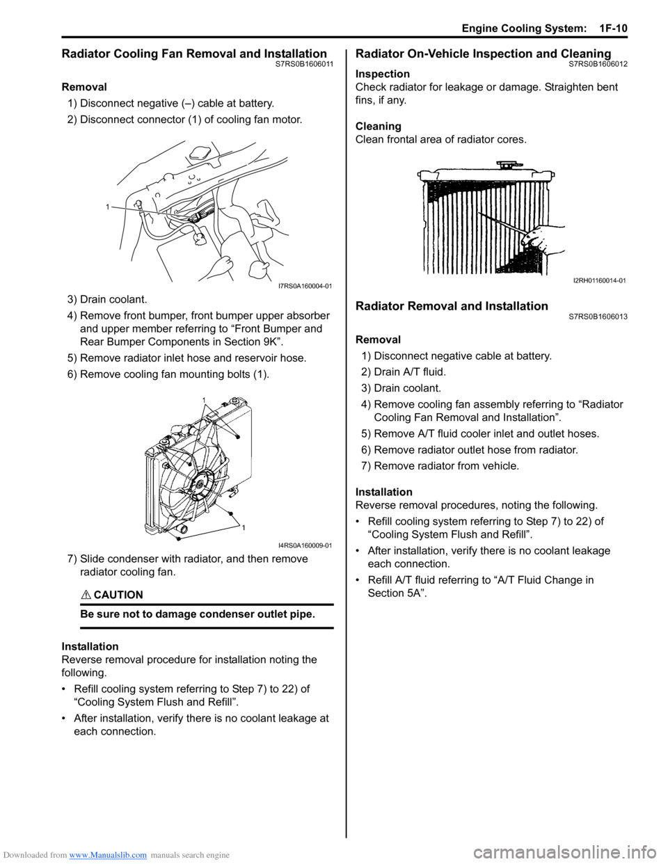
Removal1) Disconnect negative (тАУ) cable at battery.
2) Disconnect connector (1) of cooling fan motor.
3) Drain coolant.
4) Remove front bumper, front bumper upper absorber and upper member referring to тАЬFront Bumper and
Rear Bumper Componen ts in Section 9KтАЭ.
5) Remove radiator inlet hose and reservoir hose.
6) Remove cooling fan mounting bolts (1).
7) Slide condenser with radiator, and then remove radiator cooling fan.
CAUTION!
Be sure not to damage condenser outlet pipe.
Installation
Reverse removal procedure for installation noting the
following.
тАв Refill cooling system referring to Step 7) to 22) of тАЬCooling System Fl ush and RefillтАЭ.
тАв After installation, verify there is no coolant leakage at each connection.
Radiator On-Vehicle Inspection and CleaningS7RS0B1606012
Inspection
Check radiator for leakage or damage. Straighten bent
fins, if any.
Cleaning
Clean frontal area of radiator cores.
Radiator Removal and InstallationS7RS0B1606013
Removal
1) Disconnect negative cable at battery.
2) Drain A/T fluid.
3) Drain coolant.
4) Remove cooling fan assemb ly referring to тАЬRadiator
Cooling Fan Removal and InstallationтАЭ.
5) Remove A/T fluid cooler inlet and outlet hoses.
6) Remove radiator outlet hose from radiator.
7) Remove radiator from vehicle.
Installation
Reverse removal procedures, noting the following.
тАв Refill cooling system referrin g to Step 7) to 22) of
тАЬCooling System Flush and RefillтАЭ.
тАв After installation, verify there is no coolant leakage each connection.
тАв Refill A/T fluid referring to тАЬA/T Fluid Change in
Section 5AтАЭ.
1
I7RS0A160004-01
I4RS0A160009-01
I2RH01160014-01
Page 413 of 1496
Downloaded from www.Manualslib.com manuals search engine Charging System: 1J-3
Charging System Circuit
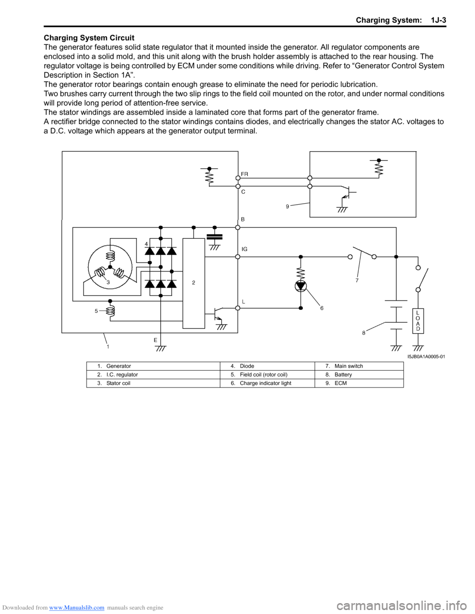
The generator features solid state regulator that it mounted inside the generator. All regulator components are
enclosed into a solid mold, and this unit along with the brus h holder assembly is attached to the rear housing. The
regulator voltage is being controlled by ECM under some cond itions while driving. Refer to тАЬGenerator Control System
Description in Section 1AтАЭ.
The generator rotor bearings contain enough grease to eliminate the need for periodic lubrication.
Two brushes carry current through the two slip rings to the field coil mounted on the rotor, and under normal conditions
will provide long period of attention-free service.
The stator windings are assembled inside a laminate d core that forms part of the generator frame.
A rectifier bridge connected to the stator windings contains diodes, and electrically changes the stator AC. voltages to
a D.C. voltage which appears at the generator output terminal.
I5JB0A1A0005-01
1. Generator 4. Diode7. Main switch
2. I.C. regulator 5. Field coil (rotor coil)8. Battery
3. Stator coil 6. Charge indicator light9. ECM
Page 562 of 1496
Downloaded from www.Manualslib.com manuals search engine 4E-23 ABS:
DTC C1063: Solenoid Valve Power Supply Driver CircuitS7RS0B4504016
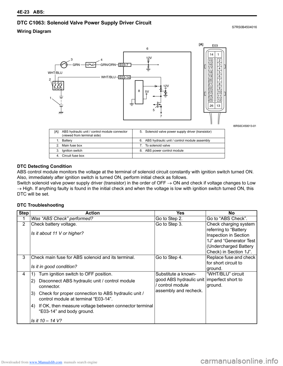
Wiring Diagram
DTC Detecting Condition
ABS control module monitors the voltage at the terminal of solenoid circuit constantly with ignition switch turned ON.
Also, immediately after ignition switch is turned ON, perform initial check as follows.
Switch solenoid valve power supply driv er (transistor) in the order of OFF тЖТ ON and check if voltage changes to Low
тЖТ High. If anything faulty is found in the initial check and when the voltage is low with ignition switch turned ON, this
DTC will be set.
DTC Troubleshooting
[A] E03
15
16
17
18
19
20
21
22
23
24
25 2
3
4
5
6
7
8
9
10
11
12
1
13
14
266
WHT/BLU
12V
5E03-14
5V
12V
8
GRN/ORNE03-7
WHT/BLU
GRN
1
2 3
4
7
I6RS0C450013-01
[A]: ABS hydraulic unit / control module connector
(viewed from terminal side) 5. Solenoid valve power supp
ly driver (transistor)
1. Battery 6. ABS hydraulic unit / control module assembly
2. Main fuse box 7. To solenoid valve
3. Ignition switch 8. ABS power control module
4. Circuit fuse box
Step Action YesNo
1 Was тАЬABS CheckтАЭ performed? Go to Step 2.Go to тАЬABS CheckтАЭ.
2 Check battery voltage.
Is it about 11 V or higher? Go to Step 3.
Check charging system
referring to тАЬBattery
Inspection in Section
1JтАЭ and тАЬGenerator Test
(Undercharged Battery
Check) in Section 1JтАЭ.
3 Check main fuse for ABS solenoid and its terminal.
Is it in good condition? Go to Step 4.
Replace fuse and check
for short circuit to
ground.
4 1) Turn ignition switch to OFF position.
2) Disconnect ABS hydraulic unit / control module connector.
3) Check for proper connection to ABS hydraulic unit / control module at terminal тАЬE03-14тАЭ.
4) If OK, then measure voltage between connector terminal тАЬE03-14тАЭ and body ground.
Is it 10 тАУ 14 V? Substitute a known-
good ABS hydraulic unit
/ control module
assembly and recheck.
тАЬWHT/BLUтАЭ circuit
imperfect short to
ground.
Page 570 of 1496
Downloaded from www.Manualslib.com manuals search engine 4E-31 ABS:
2) Bleed air from brake system referring to тАЬAir Bleeding of Brake System in Section 4AтАЭ.
3) Check each installed part for fluid leakage and perform тАЬABS Hydraulic Un it Operation CheckтАЭ.
NOTE
For new ABS hydraulic unit / control module
assembly, if тАЬABS Hydraulic Unit Operation
CheckтАЭ has not been performed, ABS
warning light may flash when ignition switch
is turned ON position.
Accordingly preform тАЬABS Hydraulic Unit
Operation CheckтАЭ to stop flashing of ABS
warning light.
Front / Rear Wheel Speed Sensor On-Vehicle
Inspection
S7RS0B4506005
Output Voltage Inspection
1) Disconnect negative cable from battery.
2) Hoist vehicle a little.
3) Disconnect wheel speed sensor connector.
4) Disconnect wheel speed grommet from vehicle body.
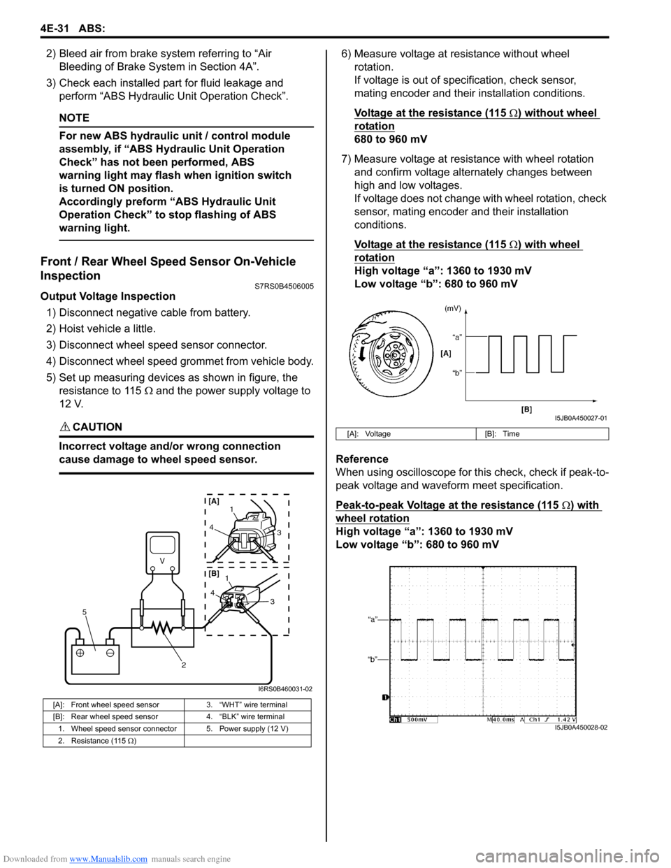
5) Set up measuring devices as shown in figure, the resistance to 115 тДж and the power supply voltage to
12 V.
CAUTION!
Incorrect voltage and/or wrong connection
cause damage to wheel speed sensor.
6) Measure voltage at resistance without wheel rotation.
If voltage is out of specification, check sensor,
mating encoder and their installation conditions.
Voltage at the resistance (115
тДж) without wheel
rotation
680 to 960 mV
7) Measure voltage at resistance with wheel rotation and confirm voltage alternately changes between
high and low voltages.
If voltage does not change with wheel rotation, check
sensor, mating encoder and their installation
conditions.
Voltage at the resistance (115
тДж) with wheel
rotation
High voltage тАЬaтАЭ: 1360 to 1930 mV
Low voltage тАЬbтАЭ: 680 to 960 mV
Reference
When using oscilloscope for this check, check if peak-to-
peak voltage and waveform meet specification.
Peak-to-peak Voltage at the resistance (115
тДж) with
wheel rotation
High voltage тАЬaтАЭ: 1360 to 1930 mV
Low voltage тАЬbтАЭ: 680 to 960 mV
[A]: Front wheel speed sensor 3. тАЬWHTтАЭ wire terminal
[B]: Rear wheel speed sensor 4. тАЬBLKтАЭ wire terminal
1. Wheel speed sensor connector 5. Power supply (12 V)
2. Resistance (115 тДж )
V
2
5
41
3
43
1
[A]
[B]
I6RS0B460031-02
[A]: Voltage [B]: Time
I5JB0A450027-01
I5JB0A450028-02
Page 632 of 1496
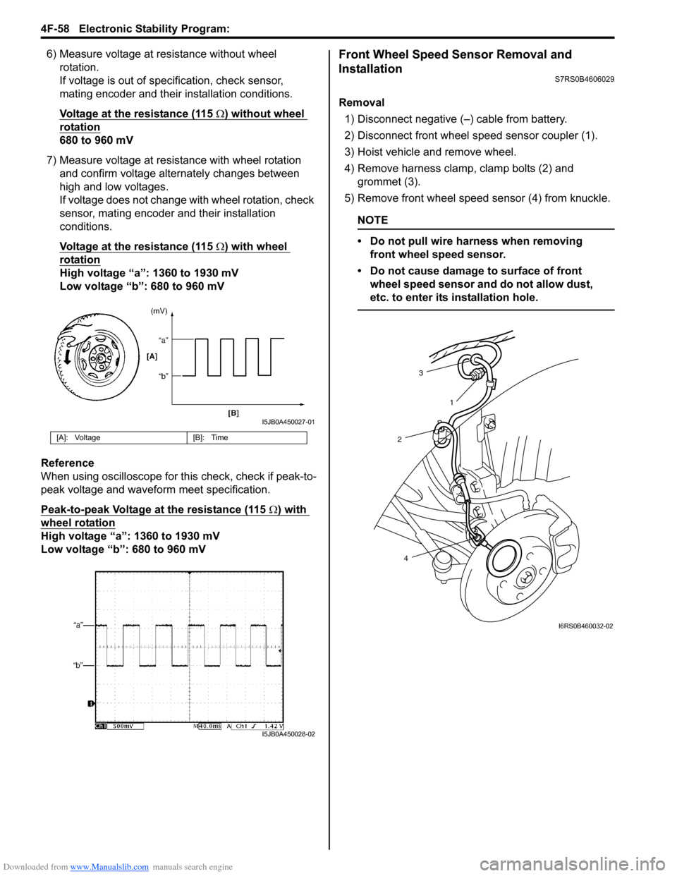
Downloaded from www.Manualslib.com manuals search engine 4F-58 Electronic Stability Program:
6) Measure voltage at resistance without wheel rotation.
If voltage is out of specification, check sensor,
mating encoder and their installation conditions.
Voltage at the resistance (115
тДж) without wheel
rotation
680 to 960 mV
7) Measure voltage at resistance with wheel rotation and confirm voltage alternately changes between
high and low voltages.
If voltage does not change with wheel rotation, check
sensor, mating encoder and their installation
conditions.
Voltage at the resistance (115
тДж) with wheel
rotation
High voltage тАЬaтАЭ: 1360 to 1930 mV
Low voltage тАЬbтАЭ: 680 to 960 mV
Reference
When using oscilloscope for this check, check if peak-to-
peak voltage and waveform meet specification.
Peak-to-peak Voltage at the resistance (115
тДж) with
wheel rotation
High voltage тАЬaтАЭ: 1360 to 1930 mV
Low voltage тАЬbтАЭ: 680 to 960 mV
Front Wheel Speed Sensor Removal and
Installation
S7RS0B4606029
Removal
1) Disconnect negative (тАУ) cable from battery.
2) Disconnect front wheel speed sensor coupler (1).
3) Hoist vehicle and remove wheel.
4) Remove harness clamp, clamp bolts (2) and grommet (3).
5) Remove front wheel speed sensor (4) from knuckle.
NOTE
тАв Do not pull wire harness when removing front wheel speed sensor.
тАв Do not cause damage to surface of front wheel speed sensor and do not allow dust,
etc. to enter its installation hole.
[A]: Voltage [B]: Time
I5JB0A450027-01
I5JB0A450028-02
3
2
4 1
I6RS0B460032-02
Page 662 of 1496

Downloaded from www.Manualslib.com manuals search engine 5A-18 Automatic Transmission/Transaxle:
Visual InspectionS7RS0B5104002
Visually check the following parts and systems.
Malfunction Indicator Lamp (MIL) CheckS7RS0B5104003
Refer to the same item in тАЬMalfunction Indicator Lam p (MIL) Check in Section 1AтАЭ for checking procedure.
Transmission Warning Light CheckS7RS0B5104004
1) Turn ignition switch ON.
2) Check that transmission warning light lights for about 2 тАУ 4 sec. and then goes OFF.
If anything faulty is found, advance тАЬTransmission Warn ing Light Circuit Check тАУ Light Does Not Come тАЬONтАЭ at
Ignition Switch ONтАЭ or тАЬTransmission Warning Light Circu it Check тАУ Light Remains тАЬONтАЭ at Ignition Switch ONтАЭ.
Inspection item Referring
тАв A/T fluid ----- level, leakage, color тАЬAutomatic Transaxle Fluid Level Inspection in Section 0BтАЭ
тАв A/T fluid hoses ----- disconnection, looseness, deterioration тАЬA/T Fluid Cooler Hoses ReplacementтАЭ
тАв A/T select cable ----- installation тАЬS elect Cable Removal and InstallationтАЭ
тАв Engine oil ----- level, leakage тАЬEngine Oil and Filter Change in Section 0BтАЭ
тАв Engine coolant ----- level, leakage тАЬEngine Coolant Change in Section 0BтАЭ
тАв Engine mountings ----- play, looseness, damage тАЬEngine Assembly Removal and Installation in Section 1DтАЭ
тАв Suspension ----- play, looseness тАЬSuspension, Wheels and Tires Symptom Diagnosis in Section 2AтАЭ
тАв Drive shafts ----- damage тАЬFront Drive Shaft Assembly On-Vehicle Inspection in Section 3AтАЭ
тАв Battery ----- indicator condition, corrosion of terminal тАЬBattery Inspection in Section 1JтАЭ
тАв Connectors of electric wire harness ----- disconnection, friction тАЬElectronic Shift Control System Components
LocationтАЭ
тАв Fuses ----- burning
тАв Parts ----- installation, damage
тАв Bolts ----- looseness
тАв Other parts that can be checked visually
Also check the following items at engine start, if possible.
тАв Transmission warning light (if equipped) ----- Operation тАЬTransmission Warning Light CheckтАЭ
тАв Malfunction indicator lamp ----- Operation тАЬMalfunction Indicator Lamp (MIL) CheckтАЭ
тАв Charge warning lamp ----- Operation тАЬGenerator Symptom Diagnosis in Section 1JтАЭ
тАв Engine oil pressure warning lamp ----- Operation тАЬOil Pressure Warning Ligh t Symptom Diagnosis in
Section 9CтАЭ
тАв Engine coolant temp. meter ----- Operation тАЬEngine Coolant Temperature (ECT) Meter
Symptom Diagnosis in Section 9CтАЭ
тАв Other parts that can be checked visually
I4RS0A510008-01