Full manuals SUZUKI SWIFT 2005 2.G Service Workshop Manual
[x] Cancel search | Manufacturer: SUZUKI, Model Year: 2005, Model line: SWIFT, Model: SUZUKI SWIFT 2005 2.GPages: 1496, PDF Size: 34.44 MB
Page 1376 of 1496
Downloaded from www.Manualslib.com manuals search engine 9J-7 Hood / Fenders / Doors:
WARNING!
Handling of Rear End Door Balancer
(Damper)
• Handle balancer carefully. Do not scar or scratch exposed surface of its piston rod,
and never allow any paint or oil to stick to
its surface.
• Do not turn piston rod with balancer fully extended.
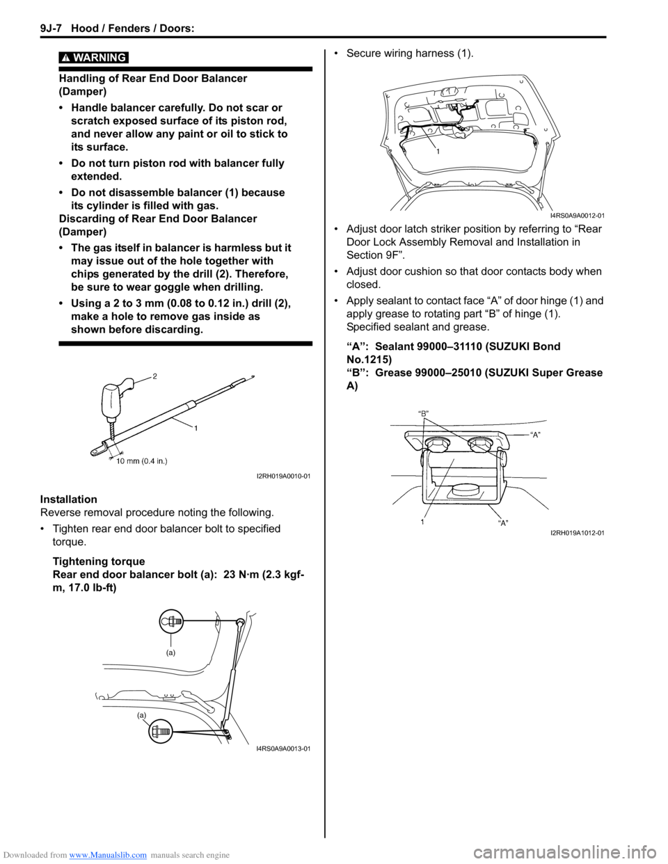
• Do not disassemble balancer (1) because its cylinder is filled with gas.
Discarding of Rear End Door Balancer
(Damper)
• The gas itself in balancer is harmless but it may issue out of the hole together with
chips generated by th e drill (2). Therefore,
be sure to wear goggle when drilling.
• Using a 2 to 3 mm (0.08 to 0.12 in.) drill (2),
make a hole to remove gas inside as
shown before discarding.
Installation
Reverse removal procedure noting the following.
• Tighten rear end door balancer bolt to specified torque.
Tightening torque
Rear end door balancer bolt (a): 23 N·m (2.3 kgf-
m, 17.0 lb-ft) • Secure wiring harness (1).
• Adjust door latch striker position by referring to “Rear
Door Lock Assembly Removal and Installation in
Section 9F”.
• Adjust door cushion so that door contacts body when closed.
• Apply sealant to contact face “A” of door hinge (1) and apply grease to rotating part “B” of hinge (1).
Specified sealant and grease.
“A”: Sealant 99000–31110 (SUZUKI Bond
No.1215)
“B”: Grease 99000–25010 (SUZUKI Super Grease
A)
I2RH019A0010-01
(a)
(a)
I4RS0A9A0013-01
1
I4RS0A9A0012-01
I2RH019A1012-01
Page 1389 of 1496
Downloaded from www.Manualslib.com manuals search engine Paint / Coatings: 9L-2
Plastic Parts FinishingS7RS0B9C01002
Paintable plastic parts are ABS plastic parts.
Painting
Rigid or hand ABS plastic needs no primer coating.
General acrylic lacquers can be painted properly over hard ABS plastic in terms of adherence.
1) Use cleaning solvent for paint finish to wash each part.
2) Apply conventional acrylic color lacquer to part surface.
3) Follow lacquer directions for required drying time. (Proper drying temperature range is 60 – 70 °C (140 – 158 ° F)).
Reference
Plastic parts employ not only ABS (Acrylonitrile Butadiene Styrene) plastic but also polypro pylene, vinyl, or the like
plastic. Burning test method to iden tify ABS plastic is described below.
1) Use a sharp blade to cut off a plastic sliver from the part at its hidden backside.
2) Hold sliver with pincer s and set it on fire.
3) Carefully observe condition of the burning plastic.
4) ABS plastic must raise readily dist inguishable back smoke while burning with its residue suspended in air
temporarily.
5) Polypropylene must raise no readily distinguishable smoke while burning.
Page 1404 of 1496
Downloaded from www.Manualslib.com manuals search engine 10B-1 Body Electrical Control System:
Control Systems
Body Electrical Control System
Precautions
Precautions in Diagnosing TroubleS7RS0BA200001
• Diagnostic information stored in BCM memory can be cleared as well as checked by using SUZUKI scan tool.
Before using scan tool, read its Operator ’s (Instruction) Manual carefully to have good understanding as to what
functions are available and how to use it.
• Be sure to read “Precautions for Electrical Circuit Serv ice in Section 00” before inspection and observe what is
written there.
• Communication of ECM, TCM (if equipped), ABS/ESP ® control module, steering angle sensor (ESP ® model),
keyless start control module (if equipped), combinatio n meter and BCM is established by CAN (Controller Area
Network). For detail of CAN communication for BCM, refer to “CAN Communication System Description”.
Therefore, handle CAN communication line with care referr ing to “Precaution for CAN Communication System in
Section 00”.
General Description
BCM General DescriptionS7RS0BA201001
The Body electrical Control Module (BCM) is incorporated in junction block assembly. Do not attempt removal of BCM
from junction block assembly as it may cause contact failure.
The BCM incorporates relays and controllers which are used for the following systems and controls them.
• Power door lock
• Keyless entry (if equipped)
• Door lock function of keyle ss start system (if equipped)
• Rear wiper
• Combination meter
• Interior light
• Warning buzzer
• Rear end door window defogger and door mirror heater (if equipped)
• Rear end door opener
• Theft deterrent light
Also, the BCM has a function to cause the interior light and open door warning lamp in the combination meter to turn
off when any door is left open for longer than 15 minutes to reduce wasteful battery consumption.
In addition, it is possible to check operation of actuator whic h is controlled by BCM by using the output test function of
SUZUKI scan tool to operate actuator simulatively.
Page 1444 of 1496
Downloaded from www.Manualslib.com manuals search engine 10C-1 Immobilizer Control System:
Control Systems
Immobilizer Control System
Precautions
Precautions in Diagnosing TroublesS7RS0BA300001
• Before confirming the diagnostic trouble code (DTC),
do not disconnect connector from ECM, battery cable
from battery, ground wire harness, or main fuse. Such
disconnection will erase DTC stored in ECM.
• DTC stored in ECM memory can be checked as well as cleared by using SUZUKI scan tool. Before using
SUZUKI scan tool, read its operator’s manual
carefully to know how to use it and what functions are
available.
• Be sure to read “Precautions for Electrical Circuit Service in Section 00” before inspection.
• Communication of ECM, BCM, keyless start control module (if equipped), ABS / ESP ® control module,
steering angle sensor (ESP ® model), combination
meter and TCM (A/T model) is established by CAN
(Controller Area Network). Therefore, handle CAN
communication lines with care referring to “Precaution
for CAN Communication System in Section 00”. For
CAN communication system, refer to description on
“CAN Communication System Description in Section
1A”.
Precaution in Replacing ECMS7RS0BA300002
• If ECM is replaced with new or used one without immobilizer control function , the engine will not be
started. In case of the above, check if the newly
installed ECM has immobilizer control function.
• After ECM is replaced with new one or used one, the transponder code in the transponder built in the
ignition key has to be registered with ECM. Or, the
engine cannot be started up. For the registration
procedure, refer to “Procedure after ECM
Replacement”.
Precautions in Handling Immobilizer Control
System
S7RS0BA300003
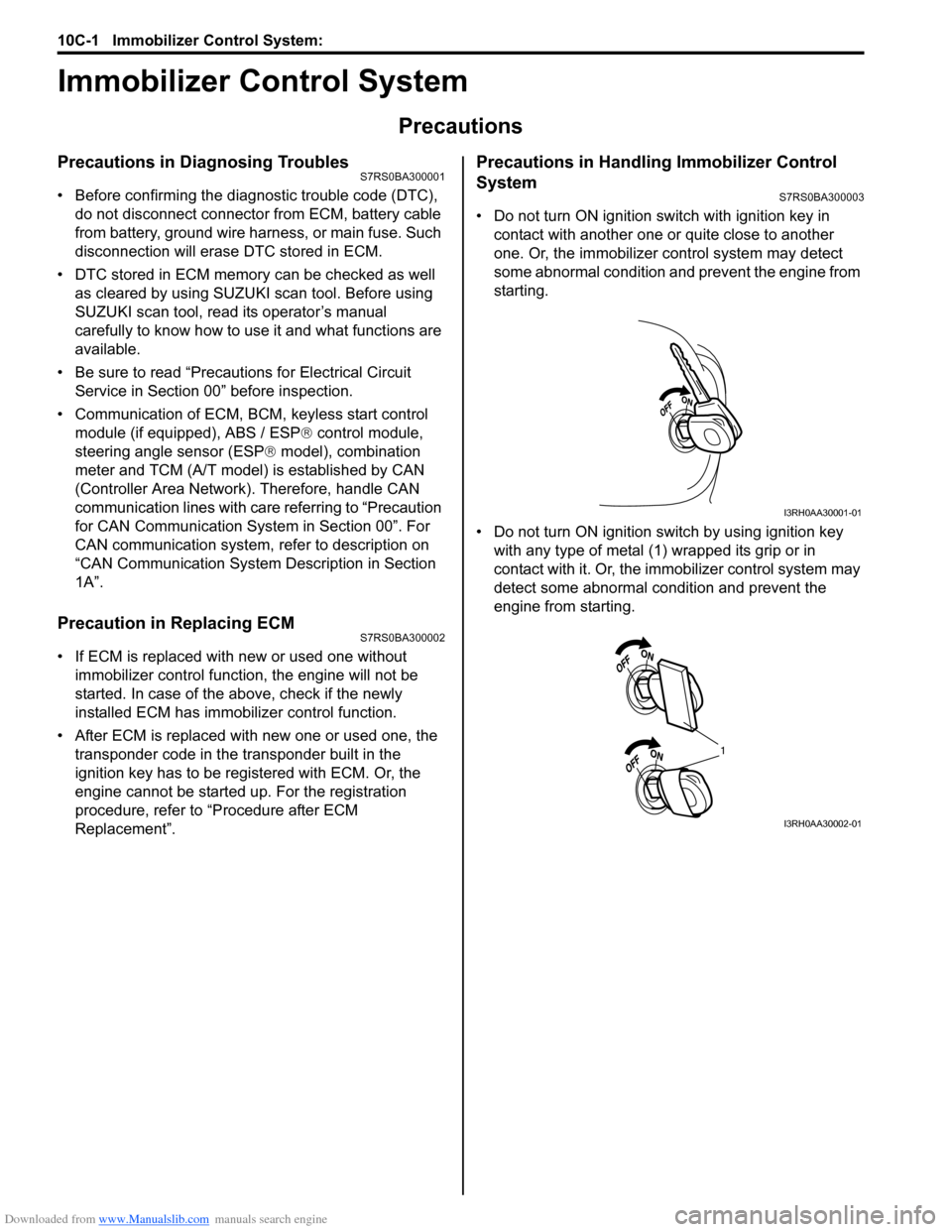
• Do not turn ON ignition sw itch with ignition key in
contact with another one or quite close to another
one. Or, the immobilizer co ntrol system may detect
some abnormal condition and prevent the engine from
starting.
• Do not turn ON ignition switch by using ignition key with any type of metal (1) wrapped its grip or in
contact with it. Or, the i mmobilizer control system may
detect some abnormal condition and prevent the
engine from starting.
I3RH0AA30001-01
1
I3RH0AA30002-01
Page 1460 of 1496
Downloaded from www.Manualslib.com manuals search engine 10C-17 Immobilizer Control System:
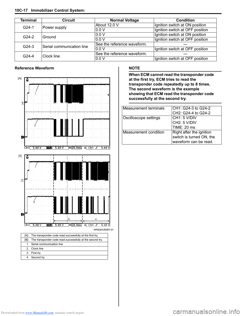
Reference WaveformNOTE
When ECM cannot read the transponder code
at the first try, ECM tries to read the
transponder code repeatedly up to 8 times.
The second waveform is the example
showing that ECM read the transponder code
successfully at the second try.
TerminalCircuit Normal Voltage Condition
G24-1 Power supply About 12.0 V
Ignition switch at ON position
0.0 V Ignition switch at OFF position
G24-2 Ground 0.0 V
Ignition switch at ON position
0.0 V Ignition switch at OFF position
G24-3 Serial communication line See the reference waveform.
—
0.0 V Ignition switch at OFF position
G24-4 Clock line See the reference waveform.
—
0.0 V Ignition switch at OFF position
[A]: The transponder code read successfully at the first try.
[B]: The transponder code read successfully at the second try.
1. Serial communication line
2. Clock line
3. First try
4. Second try
I4RS0AA30007-01
Measurement terminals CH1: G24-3 to G24-2 CH2: G24-4 to G24-2
Oscilloscope settings CH1: 5 V/DIV CH2: 5 V/DIV
TIME: 20 ms
Measurement condition Right after the ignition switch is turned ON, the
waveform can be read.
Page 1477 of 1496
Downloaded from www.Manualslib.com manuals search engine Keyless Start System: 10E-15
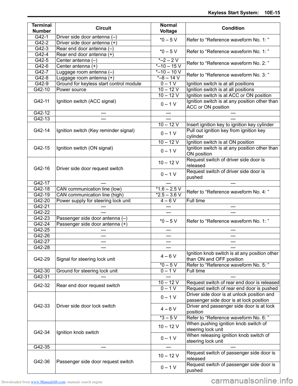
Terminal Number Circuit Normal
Vo l ta g e Condition
G42-1 Driver side door antenna (–) *0 – 5 V Refer to “Reference waveform No. 1: ”
G42-2 Driver side door antenna (+)
G42-3 Rear end door antenna (–) *0 – 5 V Refer to “Reference waveform No. 1: ”
G42-4 Rear end door antenna (+)
G42-5 Center antenna (–) *–2 – 2 V Refer to “Reference waveform No. 2: ”
G42-6 Center antenna (+) *–10 – 15 V
G42-7 Luggage room antenna (–) *–10 – 10 V Refer to “Reference waveform No. 3: ”
G42-8 Luggage room antenna (+) *–8 – 14 V
G42-9 Ground for keyless start control module 0 – 1 V Ignition switch is at all positions
G42-10 Power source 10 – 12 V Ignition switch is at all positions
G42-11 Ignition switch (ACC signal) 10 – 12 V Ignition switch is at ACC or ON position
0 – 1 V Ignition switch is at any position other than
ACC or ON position
G42-12 — — —
G42-13 — — —
G42-14 Ignition switch (Key reminder signal) 10 – 12 V Insert ignition key to ignition key cylinder
0 – 1 V Pull out ignition key from ignition key
cylinder
G42-15 Ignition switch (ON signal) 10 – 12 V Ignition switch is at ON position
0 – 1 V Ignition switch is at any position other than
ON position
G42-16 Driver side door request switch 10 – 12 V
Request switch of driver side door is
released
0 – 1 V Request switch of driver side door is
pushed
G42-17 — — —
G42-18 CAN communication line (low) *1.6 – 2.5 V Refer to “Reference waveform No. 4: ”
G42-19 CAN communication line (high) *2.5 – 3.6 V
G42-20 Power supply for steering lock unit 4 – 6 V Full time
G42-21 — — —
G42-22 — — —
G42-23 Passenger side door antenna (–) *0 – 5 V Refer to “Reference waveform No. 1: ”
G42-24 Passenger side door antenna (+)
G42-25 — — —
G42-26 — — —
G42-27 — — —
G42-28 — — —
G42-29 Signal for steering lock unit 4 – 6 VIgnition knob switch is at any position other
than ON and OFF position
*0 – 5 V Refer to “Reference waveform No. 5: ”
G42-30 Ground for steering lock unit 0 – 1 V Full time
G42-31 — — —
G42-32 Rear end door request switch 10 – 12 V Request switch of rear end door is released
0 – 1 V Request switch of rear end door is pushed
G42-33 Driver side door lock switch 0 – 1 V
Driver side door is at unlock position and
passenger side door is at lock position
4 – 6 V Driver and passenger side door is at lock
position
*3 – 5 V Refer to “Reference waveform No. 6: ”
G42-34 Ignition knob switch 10 – 12 V
When pushing ignition knob switch of
steering lock unit
0 – 1 V When releasing ignition knob switch of
steering lock unit
G42-35 — — —
G42-36 Passenger side door request switch 10 – 12 V
Request switch of passenger side door is
released
0 – 1 V Request switch of passenger side door is
pushed