Transmission to engine SUZUKI SWIFT 2005 2.G Service Workshop Manual
[x] Cancel search | Manufacturer: SUZUKI, Model Year: 2005, Model line: SWIFT, Model: SUZUKI SWIFT 2005 2.GPages: 1496, PDF Size: 34.44 MB
Page 755 of 1496

Downloaded from www.Manualslib.com manuals search engine Automatic Transmission/Transaxle: 5A-111
8) Remove fluid cooler pipes (1) and pipe union (2).
9) Remove fluid level gauge (3) and fluid filler tube (4).
10) Remove oil pan (1) and oil pan gasket (2).
NOTE
• For removal of oil pan, do not turn transaxle over as this will contaminate
valve body with foreign materials in
bottom of oil pan.
• When removing oil pan, tap around it lightly with plastic ha mmer. Do not force it
off by using screwdriver or the like.
11) Remove oil strain er assembly (1). 12) Disconnect connectors (2) from solenoid valves and
transmission fluid temperature sensor (1).
13) Remove valve body assembly bolts.
CAUTION!
Be careful not to let manual valve fall off
when removing valve body assembly.
NOTE
There are five kinds of bolts (bolts A (1), B (2),
C (3), D (4) and E (5)) fixing valve body
assembly.
14) Remove manual valve rod (1) from manual valve lever (2), then remove valve body assembly (3).
1 2
4
3
I3RM0B510059-01
I2RH0B510086-01
I2RH0B510087-01
1 2I4RS0A510027-01
I2RH0B510089-01
I2RH0B510090-01
Page 756 of 1496
Downloaded from www.Manualslib.com manuals search engine 5A-112 Automatic Transmission/Transaxle:
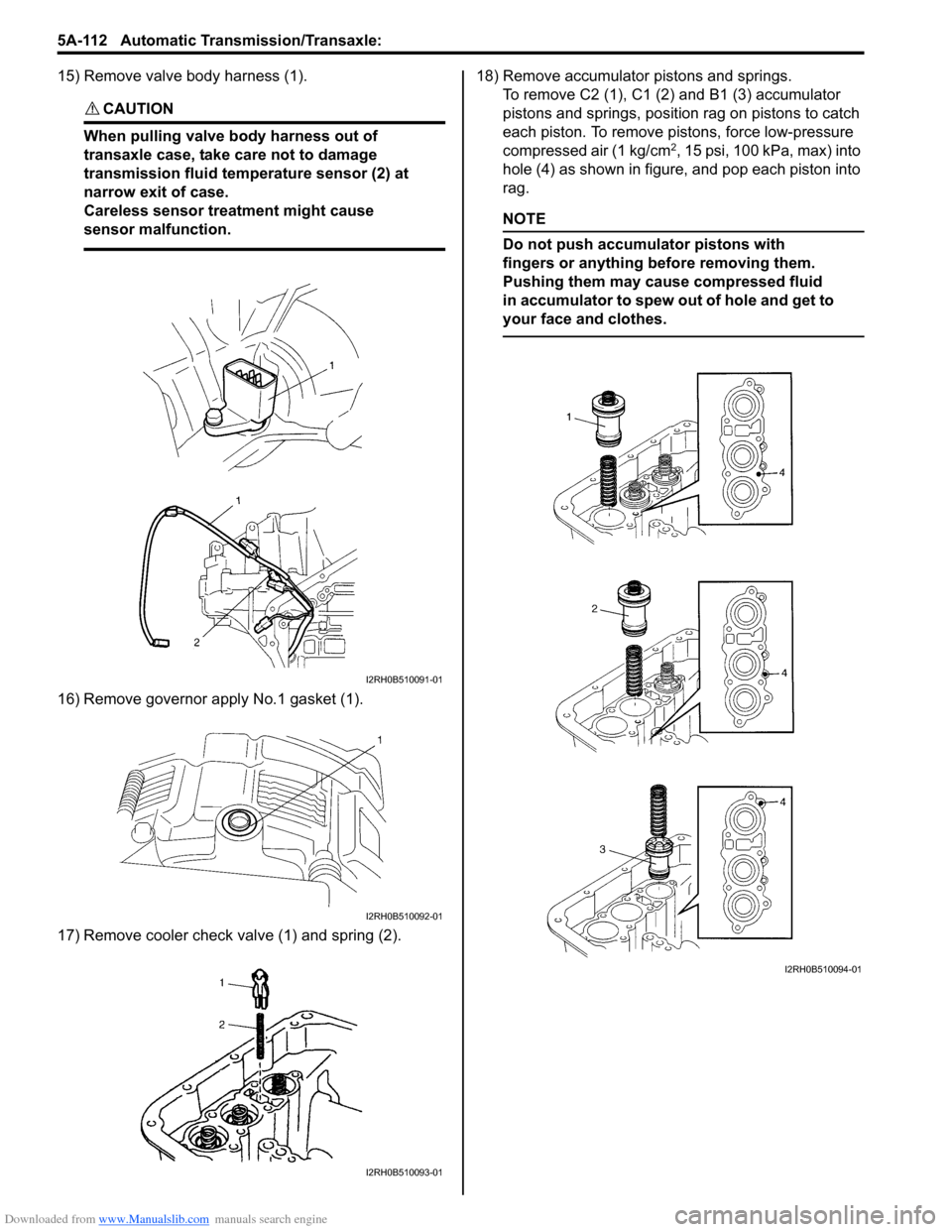
15) Remove valve body harness (1).
CAUTION!
When pulling valve body harness out of
transaxle case, take care not to damage
transmission fluid temperature sensor (2) at
narrow exit of case.
Careless sensor treatment might cause
sensor malfunction.
16) Remove governor apply No.1 gasket (1).
17) Remove cooler check valve (1) and spring (2).18) Remove accumulator pistons and springs.
To remove C2 (1), C1 (2) and B1 (3) accumulator
pistons and springs, position rag on pistons to catch
each piston. To remove pistons, force low-pressure
compressed air (1 kg/cm
2, 15 psi, 100 kPa, max) into
hole (4) as shown in figure, and pop each piston into
rag.
NOTE
Do not push accumulator pistons with
fingers or anything before removing them.
Pushing them may cause compressed fluid
in accumulator to spew out of hole and get to
your face and clothes.
I2RH0B510091-01
I2RH0B510092-01
I2RH0B510093-01
I2RH0B510094-01
Page 757 of 1496

Downloaded from www.Manualslib.com manuals search engine Automatic Transmission/Transaxle: 5A-113
19) Remove transaxle case plug (1).
20) Remove torque converter housing bolts.
21) Remove torque converter housing (1) while tapping
around it lightly with plastic hammer.
22) Remove breather hose (1).
23) Remove breather union (2).
24) Measure input shaft thrust play. Apply dial gauge onto input shaft end (1) and
measure thrust play of input shaft.
When input shaft thrust play is out of specification,
select input shaft front th rust bearing with proper
thickness from among the list below and replace it.
Special tool
(A): 09900–20607
(B): 09900-20701
Input shaft thrust play
0.3 – 0.9 mm (0.012 – 0.035 in.)
Available input shaft front thrust bearing
thickness
: 3.45, 4.05 mm (0.136, 0.159 in.) 25) Remove oil pump assembly (1).
26) Remove direct clutch assembly (1).
27) Remove input shaft front thrust bearing (1).
NOTE
If input shaft front thrust bearing is not
found, it may have been taken out with oil
pump assembly.
I2RH0B510095-01
I3RM0B510060-01
1
2
I2RH0B510097-01
I2RH0B510098-01
I2RH0B510099-01
I2RH0B510100-01
I2RH0B510101-01
Page 758 of 1496
Downloaded from www.Manualslib.com manuals search engine 5A-114 Automatic Transmission/Transaxle:
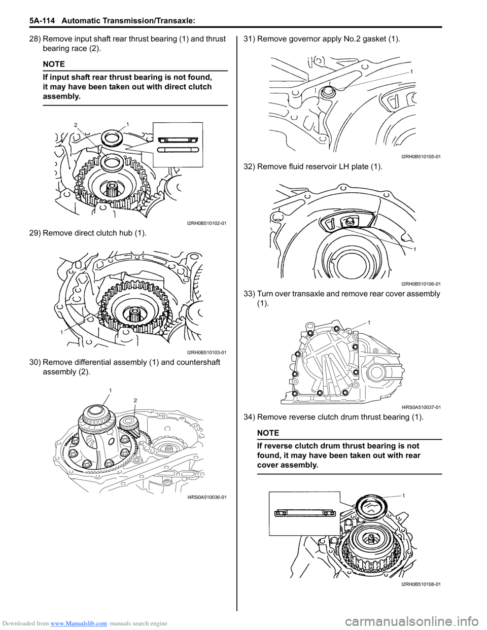
28) Remove input shaft rear thrust bearing (1) and thrust bearing race (2).
NOTE
If input shaft rear thrust bearing is not found,
it may have been taken out with direct clutch
assembly.
29) Remove direct clutch hub (1).
30) Remove differential assembly (1) and countershaft assembly (2). 31) Remove governor apply No.2 gasket (1).
32) Remove fluid reservoir LH plate (1).
33) Turn over transaxle and remove rear cover assembly
(1).
34) Remove reverse clutch drum thrust bearing (1).
NOTE
If reverse clutch drum thrust bearing is not
found, it may have been taken out with rear
cover assembly.
I2RH0B510102-01
I2RH0B510103-01
1 2
I4RS0A510036-01
I2RH0B510105-01
I2RH0B510106-01
1
I4RS0A510037-01
I2RH0B510108-01
Page 759 of 1496
Downloaded from www.Manualslib.com manuals search engine Automatic Transmission/Transaxle: 5A-115
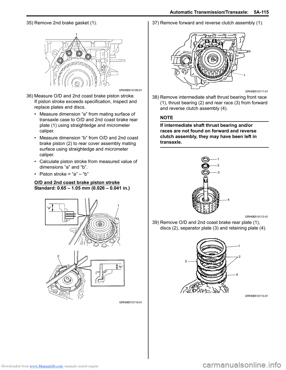
35) Remove 2nd brake gasket (1).
36) Measure O/D and 2nd coast brake piston stroke.If piston stroke exceeds specification, inspect and
replace plates and discs.
• Measure dimension “a” from mating surface of transaxle case to O/D and 2nd coast brake rear
plate (1) using straightedge and micrometer
caliper.
• Measure dimension “b” from O/D and 2nd coast brake piston (2) to rear cover assembly mating
surface using straightedge and micrometer
caliper.
• Calculate piston stroke from measured value of dimensions “a” and “b”.
• Piston stroke = “a” – “b”
O/D and 2nd coast brake piston stroke
Standard: 0.65 – 1.05 mm (0.026 – 0.041 in.) 37) Remove forward and reverse clutch assembly (1).
38) Remove intermediate shaft thrust bearing front race
(1), thrust bearing (2) and rear race (3) from forward
and reverse clutch assembly (4).
NOTE
If intermediate shaft thrust bearing and/or
races are not found on forward and reverse
clutch assembly, they may have been left in
transaxle.
39) Remove O/D and 2nd coast brake rear plate (1), discs (2), separator plate (3) and retaining plate (4).
I2RH0B510109-01
I2RH0B510110-01
I2RH0B510111-01
I2RH0B510112-01
I2RH0B510113-01
Page 760 of 1496
Downloaded from www.Manualslib.com manuals search engine 5A-116 Automatic Transmission/Transaxle:
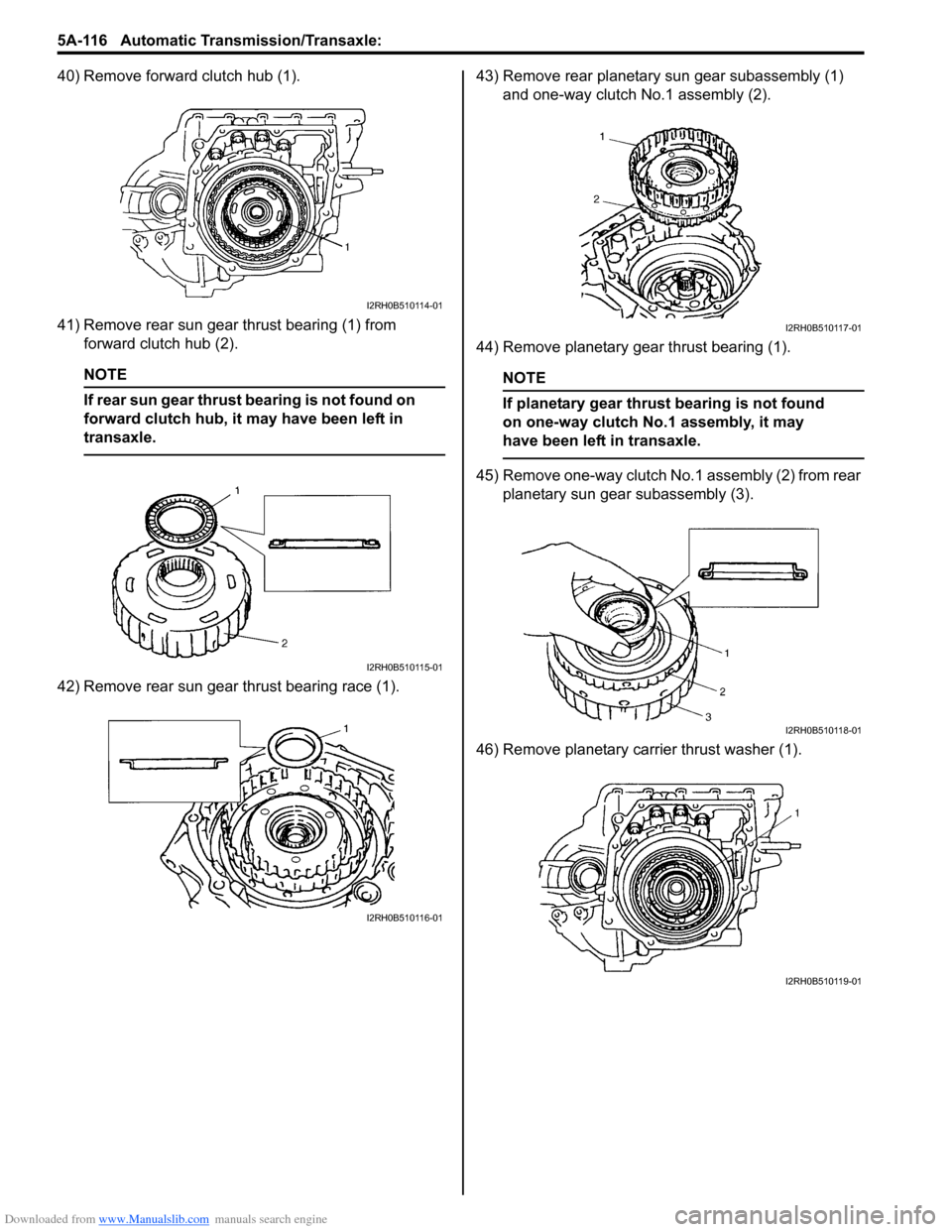
40) Remove forward clutch hub (1).
41) Remove rear sun gear thrust bearing (1) from forward clutch hub (2).
NOTE
If rear sun gear thrust bearing is not found on
forward clutch hub, it may have been left in
transaxle.
42) Remove rear sun gear thrust bearing race (1). 43) Remove rear planetary sun gear subassembly (1)
and one-way clutch No.1 assembly (2).
44) Remove planetary gear thrust bearing (1).
NOTE
If planetary gear thrust bearing is not found
on one-way clutch No.1 assembly, it may
have been left in transaxle.
45) Remove one-way clutch No.1 assembly (2) from rear planetary sun gear subassembly (3).
46) Remove planetary carrier thrust washer (1).
I2RH0B510114-01
I2RH0B510115-01
I2RH0B510116-01
I2RH0B510117-01
I2RH0B510118-01
I2RH0B510119-01
Page 761 of 1496
Downloaded from www.Manualslib.com manuals search engine Automatic Transmission/Transaxle: 5A-117
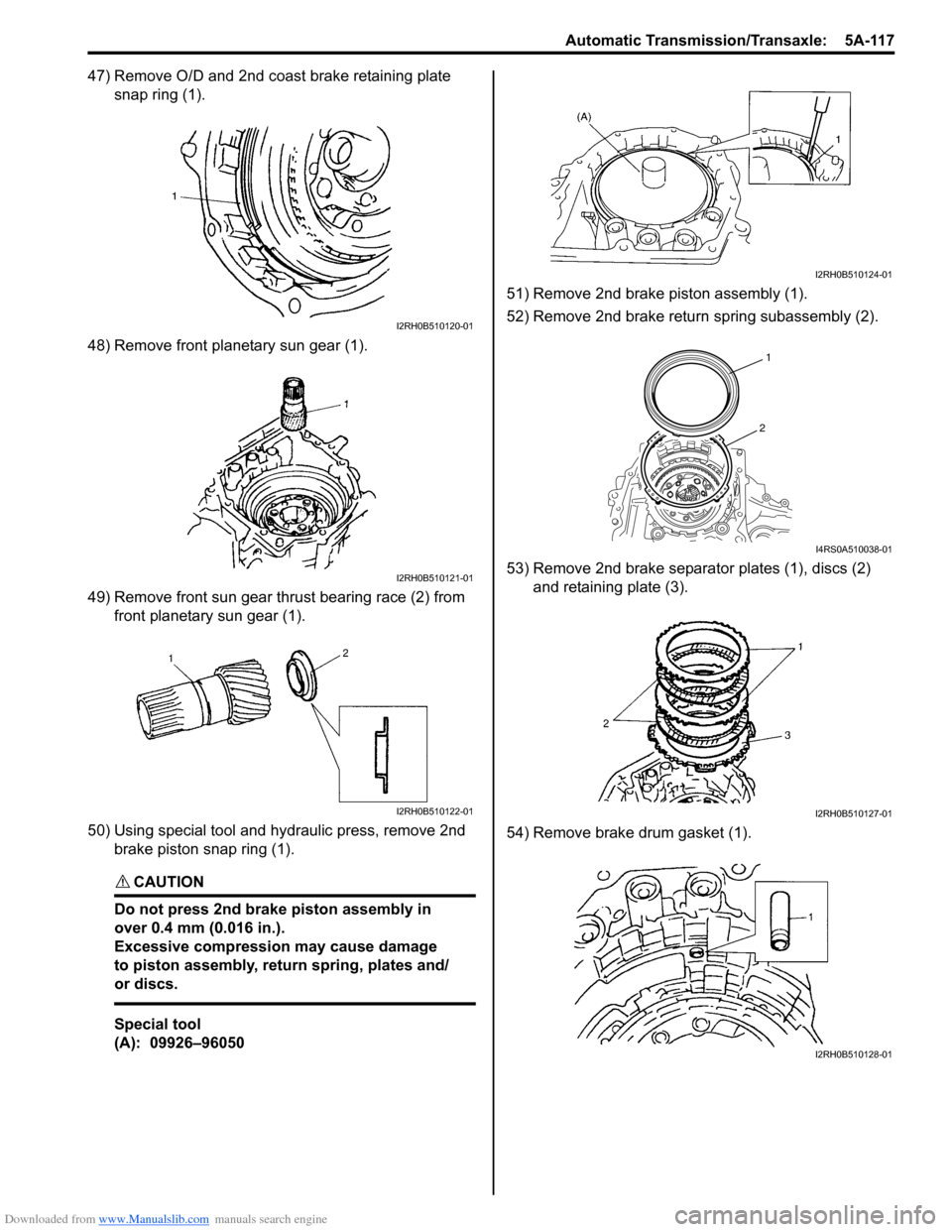
47) Remove O/D and 2nd coast brake retaining plate snap ring (1).
48) Remove front planetary sun gear (1).
49) Remove front sun gear thrust bearing race (2) from front planetary sun gear (1).
50) Using special tool and hydraulic press, remove 2nd brake piston snap ring (1).
CAUTION!
Do not press 2nd brake piston assembly in
over 0.4 mm (0.016 in.).
Excessive compression may cause damage
to piston assembly, return spring, plates and/
or discs.
Special tool
(A): 09926–96050 51) Remove 2nd brake piston assembly (1).
52) Remove 2nd brake return spring subassembly (2).
53) Remove 2nd brake separator plates (1), discs (2)
and retaining plate (3).
54) Remove brake drum gasket (1).
I2RH0B510120-01
I2RH0B510121-01
I2RH0B510122-01
I2RH0B510124-01
1
2
I4RS0A510038-01
I2RH0B510127-01
I2RH0B510128-01
Page 762 of 1496
Downloaded from www.Manualslib.com manuals search engine 5A-118 Automatic Transmission/Transaxle:
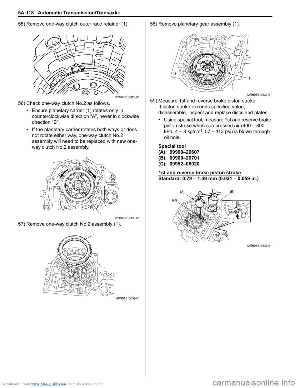
55) Remove one-way clutch outer race retainer (1).
56) Check one-way clutch No.2 as follows.• Ensure planetary carrier (1) rotates only in counterclockwise direction “A”, never in clockwise
direction “B”.
• If the planetary carrier rotates both ways or does not rotate either way, one-way clutch No.2
assembly will need to be replaced with new one-
way clutch No.2 assembly.
57) Remove one-way clutch No.2 assembly (1). 58) Remove planetary gear assembly (1).
59) Measure 1st and reverse brake piston stroke.
If piston stroke exce eds specified value,
disassemble, inspect and replace discs and plates.
• Using special tool, measure 1st and reserve brake piston stroke when compressed air (400 – 800
kPa, 4 – 8 kg/cm
2, 57 – 113 psi) is blown through
oil hole.
Special tool
(A): 09900–20607
(B): 09900–20701
(C): 09952–06020
1st and reverse brake piston stroke
Standard: 0.79 – 1.49 mm (0.031 – 0.059 in.)
I2RH0B510129-01
I2RH0B510130-01
1
I4RS0A510039-01
I2RH0B510132-01
I2RH0B510133-01
Page 763 of 1496
Downloaded from www.Manualslib.com manuals search engine Automatic Transmission/Transaxle: 5A-119
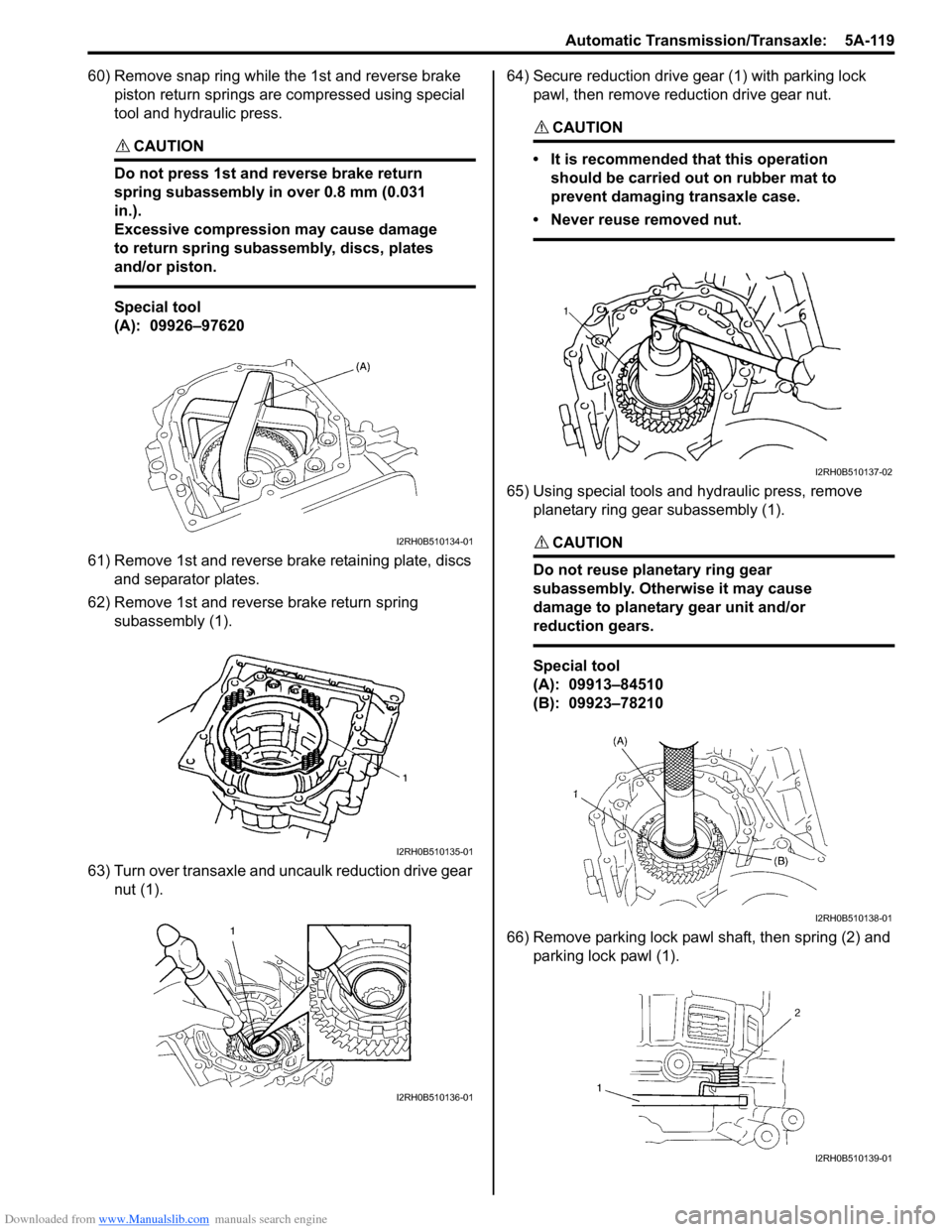
60) Remove snap ring while the 1st and reverse brake piston return springs are compressed using special
tool and hydraulic press.
CAUTION!
Do not press 1st and reverse brake return
spring subassembly in over 0.8 mm (0.031
in.).
Excessive compression may cause damage
to return spring subassembly, discs, plates
and/or piston.
Special tool
(A): 09926–97620
61) Remove 1st and reverse brake retaining plate, discs and separator plates.
62) Remove 1st and reverse brake return spring subassembly (1).
63) Turn over transaxle and uncaulk reduction drive gear nut (1). 64) Secure reduction drive gear (1) with parking lock
pawl, then remove reduction drive gear nut.
CAUTION!
• It is recommended that this operation should be carried out on rubber mat to
prevent damaging transaxle case.
• Never reuse removed nut.
65) Using special tools and hydraulic press, remove planetary ring gear subassembly (1).
CAUTION!
Do not reuse planetary ring gear
subassembly. Otherwise it may cause
damage to planetary gear unit and/or
reduction gears.
Special tool
(A): 09913–84510
(B): 09923–78210
66) Remove parking lock pawl shaft, then spring (2) and parking lock pawl (1).
I2RH0B510134-01
I2RH0B510135-01
I2RH0B510136-01
I2RH0B510137-02
I2RH0B510138-01
I2RH0B510139-01
Page 764 of 1496
Downloaded from www.Manualslib.com manuals search engine 5A-120 Automatic Transmission/Transaxle:
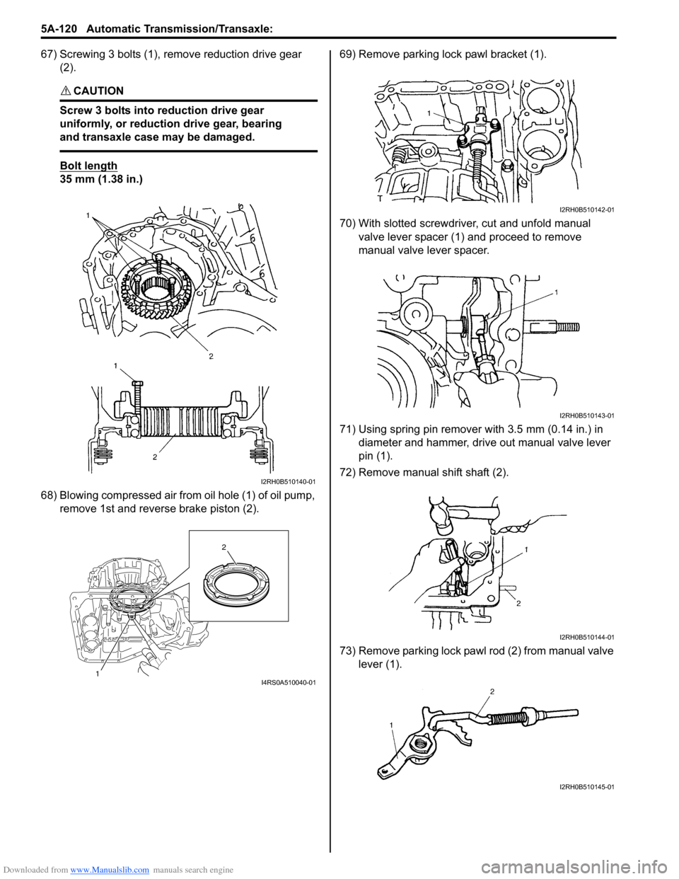
67) Screwing 3 bolts (1), remove reduction drive gear (2).
CAUTION!
Screw 3 bolts into reduction drive gear
uniformly, or reduction drive gear, bearing
and transaxle case may be damaged.
Bolt length
35 mm (1.38 in.)
68) Blowing compressed air from oil hole (1) of oil pump,
remove 1st and reverse brake piston (2). 69) Remove parking lock pawl bracket (1).
70) With slotted screwdriver, cut and unfold manual
valve lever spacer (1) and proceed to remove
manual valve lever spacer.
71) Using spring pin remover with 3.5 mm (0.14 in.) in diameter and hammer, drive out manual valve lever
pin (1).
72) Remove manual shift shaft (2).
73) Remove parking lock pawl rod (2) from manual valve lever (1).
I2RH0B510140-01
1 2I4RS0A510040-01
I2RH0B510142-01
I2RH0B510143-01
I2RH0B510144-01
I2RH0B510145-01