steering SUZUKI SWIFT 2005 2.G Service Workshop Manual
[x] Cancel search | Manufacturer: SUZUKI, Model Year: 2005, Model line: SWIFT, Model: SUZUKI SWIFT 2005 2.GPages: 1496, PDF Size: 34.44 MB
Page 926 of 1496
Downloaded from www.Manualslib.com manuals search engine 6C-44 Power Assisted Steering System:
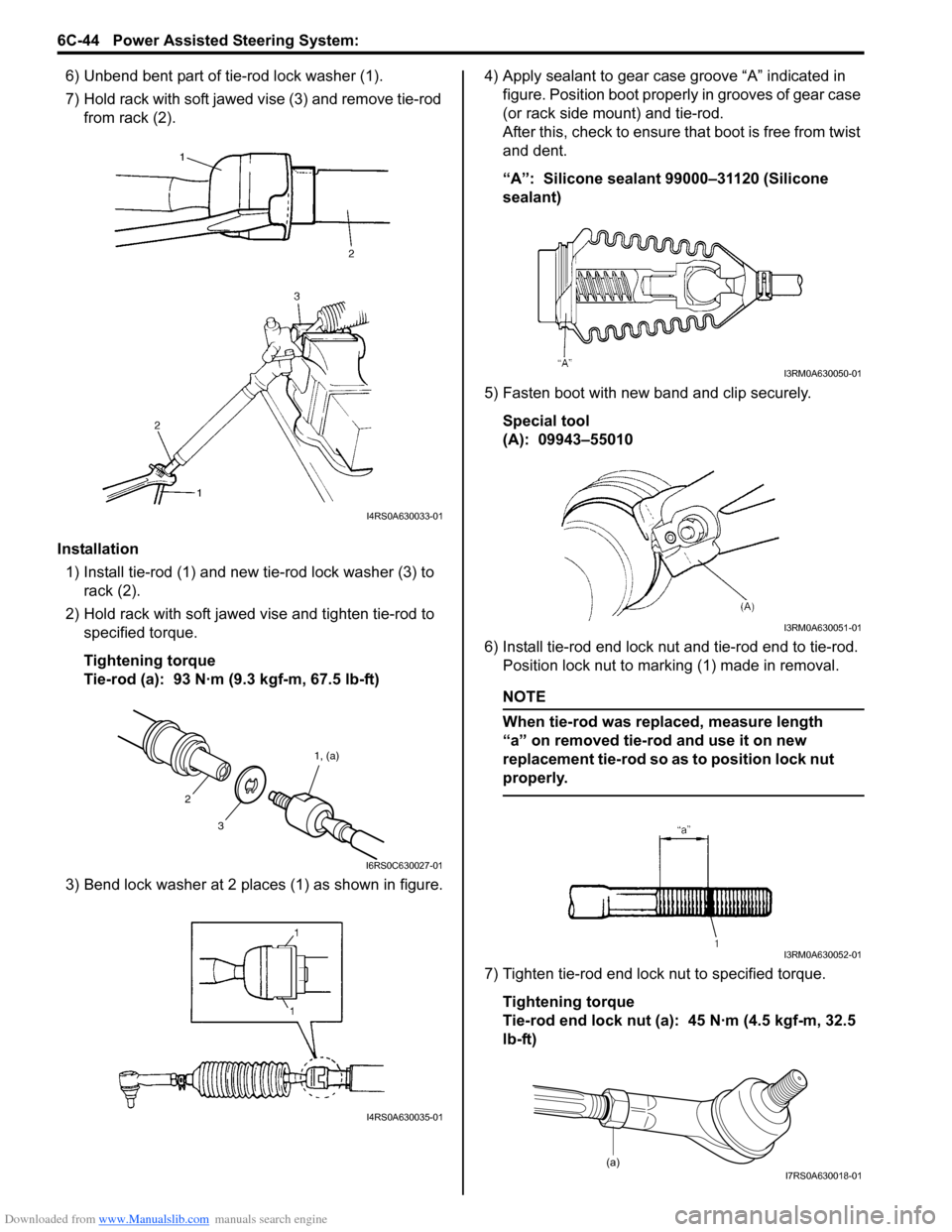
6) Unbend bent part of tie-rod lock washer (1).
7) Hold rack with soft jawed vise (3) and remove tie-rod
from rack (2).
Installation 1) Install tie-rod (1) and new tie-rod lock washer (3) to rack (2).
2) Hold rack with soft jawed vise and tighten tie-rod to specified torque.
Tightening torque
Tie-rod (a): 93 N·m (9.3 kgf-m, 67.5 lb-ft)
3) Bend lock washer at 2 places (1) as shown in figure. 4) Apply sealant to gear case groove “A” indicated in
figure. Position boot properly in grooves of gear case
(or rack side mount) and tie-rod.
After this, check to ensure that boot is free from twist
and dent.
“A”: Silicone sealant 99000–31120 (Silicone
sealant)
5) Fasten boot with new band and clip securely. Special tool
(A): 09943–55010
6) Install tie-rod end lock nut and tie-rod end to tie-rod. Position lock nut to marking (1) made in removal.
NOTE
When tie-rod was replaced, measure length
“a” on removed tie-rod and use it on new
replacement tie-rod so as to position lock nut
properly.
7) Tighten tie-rod end lock nut to specified torque.
Tightening torque
Tie-rod end lock nut (a): 45 N·m (4.5 kgf-m, 32.5
lb-ft)
I4RS0A630033-01
3 1, (a)
2
I6RS0C630027-01
I4RS0A630035-01
I3RM0A630050-01
I3RM0A630051-01
I3RM0A630052-01
(a)I7RS0A630018-01
Page 927 of 1496
Downloaded from www.Manualslib.com manuals search engine Power Assisted Steering System: 6C-45
8) Install steering gear case assembly referring to “Steering Gear Case Assembly Removal and
Installation”.
Steering Rack Plunger Removal and InstallationS7RS0B6306009
Removal
1) Remove gear case assembly referring to “Steering
Gear Case Assembly Removal and Installation”.
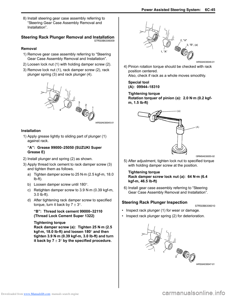
2) Loosen lock nut (1) with holding damper screw (2).
3) Remove lock nut (1), rack damper screw (2), rack plunger spring (3) and rack plunger (4).
Installation 1) Apply grease lightly to sliding part of plunger (1) against rack.
“A”: Grease 99000–25050 (SUZUKI Super
Grease E)
2) Install plunger and spring (2) as shown.
3) Apply thread lock cement to rack damper screw (3)
and tighten them as follows.
a) Tighten damper screw to 25 N ⋅m (2.5 kgf-m, 18.0
lb-ft).
b) Loosen damper screw until 180 °.
c) Retighten damper screw to 3.9 N ⋅m (0.39 kgf-m,
3.0 lb-ft).
d) After tightening rack damper screw to specified torque, turn it back by 7 ± 3°.
“B”: Thread lock cement 99000–32110
(Thread Lock Cement Super 1322)
Tightening torque
Rack damper screw (a): Tighten 25 N ⋅m (2.5
kgf-m, 18.0 lb-ft) and loosen 180° and then
tighten 3.9 N ⋅m (0.39 kgf-m, 3.0 lb-ft) and turn
it back by 7 ± 3° by the specified procedure. 4) Pinion rotation torque should be checked with rack
position centered.
Also, check if rack as a whole moves smoothly.
Special tool
(A): 09944–18310
Tightening torque
Rotation torquer of pinion (a): 2.0 N·m (0.2 kgf-
m, 1.5 lb-ft)
5) After adjustment, tighten lo ck nut to specified torque
with holding damper screw at the position.
Tightening torque
Rack damper screw lock nut (a): 64 N·m (6.4
kgf-m, 46.5 lb-ft)
6) Install gear case assembly referring to “Steering Gear Case Assembly Re moval and Installation”.
Steering Rack Plunger InspectionS7RS0B6306010
• Inspect rack plunger (1) for wear or damage.
• Inspect rack plunger spring (2) for deterioration.
I4RS0A630045-01
I4RS0A630046-01
I3RM0A630055-02
I4RS0A630047-01
Page 928 of 1496
Downloaded from www.Manualslib.com manuals search engine 6C-46 Power Assisted Steering System:
P/S Control Module Removal and InstallationS7RS0B6306011
Removal1) Disconnect negative cable at battery.
2) Remove console box.
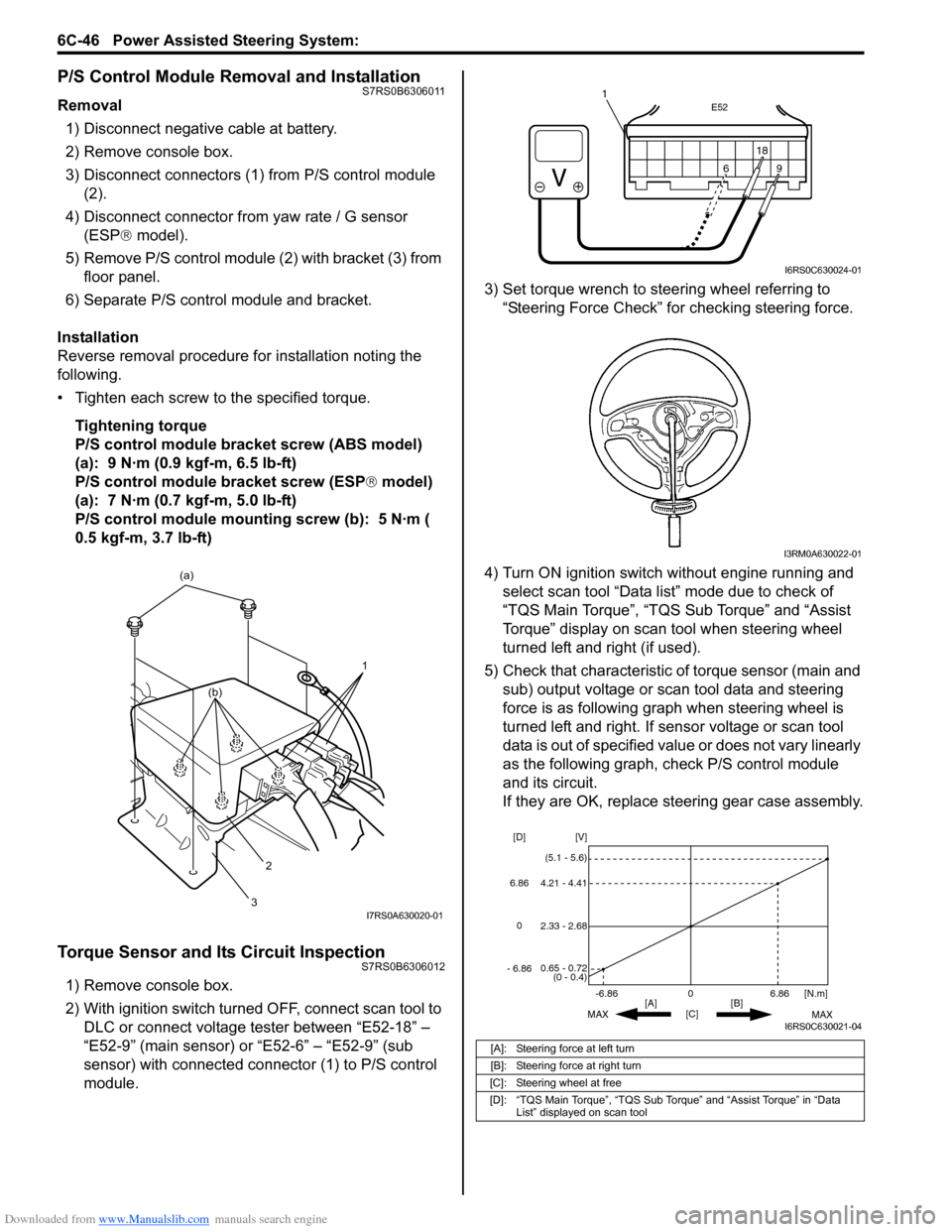
3) Disconnect connectors (1) from P/S control module (2).
4) Disconnect connector from yaw rate / G sensor
(ESP ® model).
5) Remove P/S control module (2) with bracket (3) from floor panel.
6) Separate P/S control module and bracket.
Installation
Reverse removal procedure for installation noting the
following.
• Tighten each screw to the specified torque. Tightening torque
P/S control module bracket screw (ABS model)
(a): 9 N·m (0.9 kgf-m, 6.5 lb-ft)
P/S control module bracket screw (ESP ® model)
(a): 7 N·m (0.7 kgf-m, 5.0 lb-ft)
P/S control module mounting screw (b): 5 N·m (
0.5 kgf-m, 3.7 lb-ft)
Torque Sensor and Its Circuit InspectionS7RS0B6306012
1) Remove console box.
2) With ignition switch turned OFF, connect scan tool to DLC or connect voltage tester between “E52-18” –
“E52-9” (main sensor) or “E52-6” – “E52-9” (sub
sensor) with connected connector (1) to P/S control
module. 3) Set torque wrench to stee
ring wheel referring to
“Steering Force Check” for checking steering force.
4) Turn ON ignition switch without engine running and select scan tool “Data list” mode due to check of
“TQS Main Torque”, “TQS Sub Torque” and “Assist
Torque” display on scan tool when steering wheel
turned left and right (if used).
5) Check that characteristic of torque sensor (main and sub) output voltage or scan tool data and steering
force is as following graph when steering wheel is
turned left and right. If sensor voltage or scan tool
data is out of specified value or does not vary linearly
as the following graph, check P/S control module
and its circuit.
If they are OK, replace steering gear case assembly.
1
(a)
2
3
(b)
I7RS0A630020-01
[A]: Steering force at left turn
[B]: Steering force at right turn
[C]: Steering wheel at free
[D]: “TQS Main Torque”, “TQS Sub Torque” and “Assist Torque” in “Data List” displayed on scan tool
E52
18
9
6
9
6 18
1
I6RS0C630024-01
I3RM0A630022-01
0
[C] [N.m]
MAX MAX
[B]
[A]
2.33 - 2.68 [V]
[D]
0.65 - 0.72
(0 - 0.4)
4.21 - 4.41
(5.1 - 5.6)
6.86
-6.86
0
6.86
- 6.86
I6RS0C630021-04
Page 929 of 1496
Downloaded from www.Manualslib.com manuals search engine Power Assisted Steering System: 6C-47
P/S Motor and Its Circuit InspectionS7RS0B6306013
1) Remove console box.
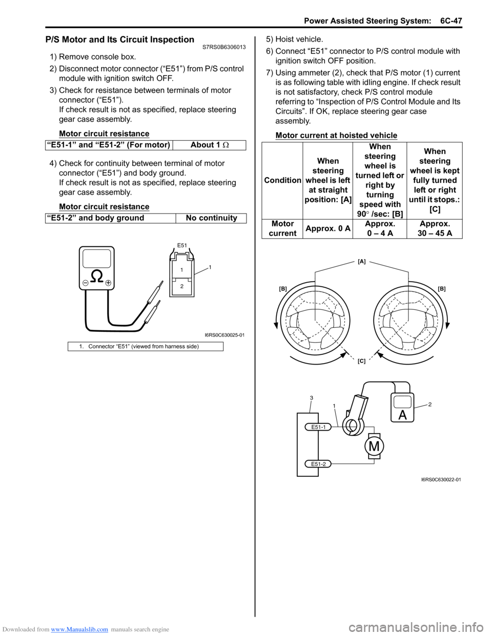
2) Disconnect motor connector (“E51”) from P/S control module with ignition switch OFF.
3) Check for resistance between terminals of motor connector (“E51”).
If check result is not as specified, replace steering
gear case assembly.
Motor circuit resistance
4) Check for continuity between terminal of motor connector (“E51”) and body ground.
If check result is not as specified, replace steering
gear case assembly.
Motor circuit resistance
5) Hoist vehicle.
6) Connect “E51” connector to P/S control module with ignition switch OFF position.
7) Using ammeter (2), check that P/S motor (1) current is as following table with id ling engine. If check result
is not satisfactory, check P/S control module
referring to “Inspection of P/S Control Module and Its
Circuits”. If OK, replace steering gear case
assembly.
Motor current at hoisted vehicle
“E51-1” and “E51-2” (For motor) About 1 Ω
“E51-2” and body ground No continuity
1. Connector “E51” (viewed from harness side)
E51
11 2
I6RS0C630025-01
Condition When
steering
wheel is left at straight
position: [A] When
steering
wheel is
turned left or right by turning
speed with
90° /sec: [B] When
steering
wheel is kept fully turned left or right
until it stops.: [C]
Motor
current Approx. 0 A Approx.
0 – 4 A Approx.
30 – 45 A
1
32
E51-1
E51-2
[C] [A]
[B] [B]
I6RS0C630022-01
Page 930 of 1496
Downloaded from www.Manualslib.com manuals search engine 6C-48 Power Assisted Steering System:
Specifications
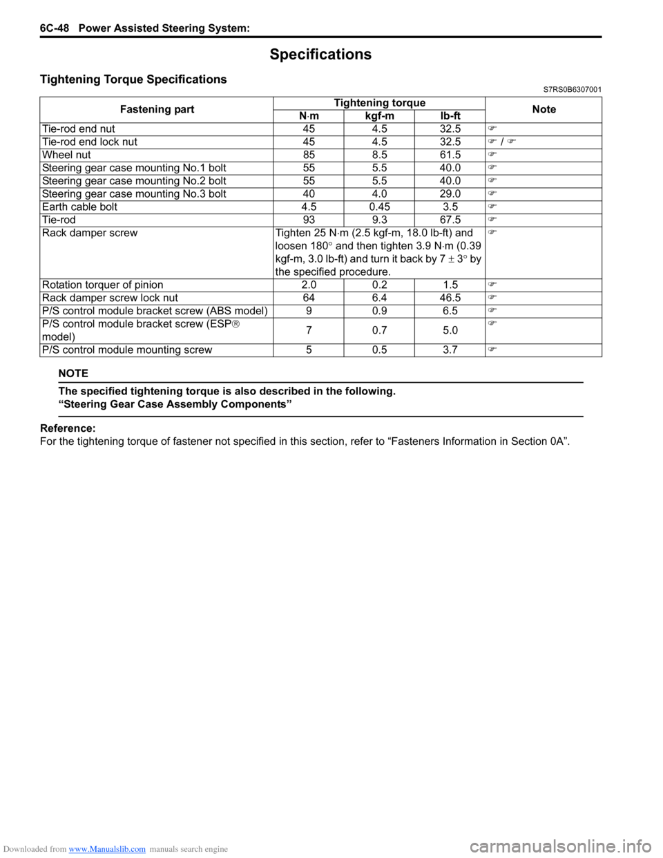
Tightening Torque SpecificationsS7RS0B6307001
NOTE
The specified tightening torque is also described in the following.
“Steering Gear Case Assembly Components”
Reference:
For the tightening torque of fastener not specified in this section, refer to “Fasteners Information in Section 0A”.
Fastening part
Tightening torque
Note
N ⋅mkgf-mlb-ft
Tie-rod end nut 454.5 32.5 �)
Tie-rod end lock nut 454.5 32.5 �) / �)
Wheel nut 858.5 61.5 �)
Steering gear case mounting No.1 bolt 555.5 40.0 �)
Steering gear case mounting No.2 bolt 555.5 40.0 �)
Steering gear case mounting No.3 bolt 404.0 29.0 �)
Earth cable bolt 4.5 0.45 3.5�)
Tie-rod 939.3 67.5 �)
Rack damper screw Tighten 25 N⋅m (2.5 kgf-m, 18.0 lb-ft) and
loosen 180 ° and then tighten 3.9 N ⋅m (0.39
kgf-m, 3.0 lb-ft) and turn it back by 7 ± 3° by
the specified procedure. �)
Rotation torquer of pinion 2.00.2 1.5 �)
Rack damper screw lock nut 646.4 46.5 �)
P/S control module bracket screw (ABS model) 9 0.9 6.5�)
P/S control module bracket screw (ESP ®
model) 70
.7 5 .0 �)
P/S control module mounting screw 50.5 3.7 �)
Page 931 of 1496
Downloaded from www.Manualslib.com manuals search engine Power Assisted Steering System: 6C-49
Special Tools and Equipment
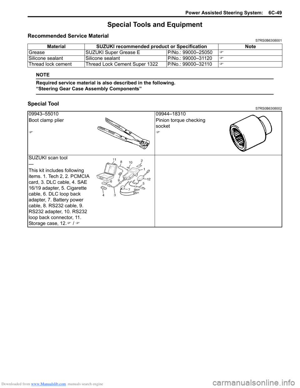
Recommended Service MaterialS7RS0B6308001
NOTE
Required service material is also described in the following.
“Steering Gear Case Assembly Components”
Special ToolS7RS0B6308002
Material SUZUKI recommended product or Specification Note
Grease SUZUKI Super Grease E P/No.: 99000–25050�)
Silicone sealant Silicone sealant P/No.: 99000–31120�)
Thread lock cement Thread Lock Cement Super 1322 P/No.: 99000–32110 �)
09943–5501009944–18310
Boot clamp plier Pinion torque checking
socket
�)�)
SUZUKI scan tool
—
This kit includes following
items. 1. Tech 2, 2. PCMCIA
card, 3. DLC cable, 4. SAE
16/19 adapter, 5. Cigarette
cable, 6. DLC loop back
adapter, 7. Battery power
cable, 8. RS232 cable, 9.
RS232 adapter, 10. RS232
loop back connector, 11.
Storage case, 12. �) / �)
Page 932 of 1496

Downloaded from www.Manualslib.com manuals search engine 6C-50 Power Assisted Steering System:
Page 937 of 1496
Downloaded from www.Manualslib.com manuals search engine Heater and Ventilation: 7A-1
HVAC
Heater and Ventilation
General Description
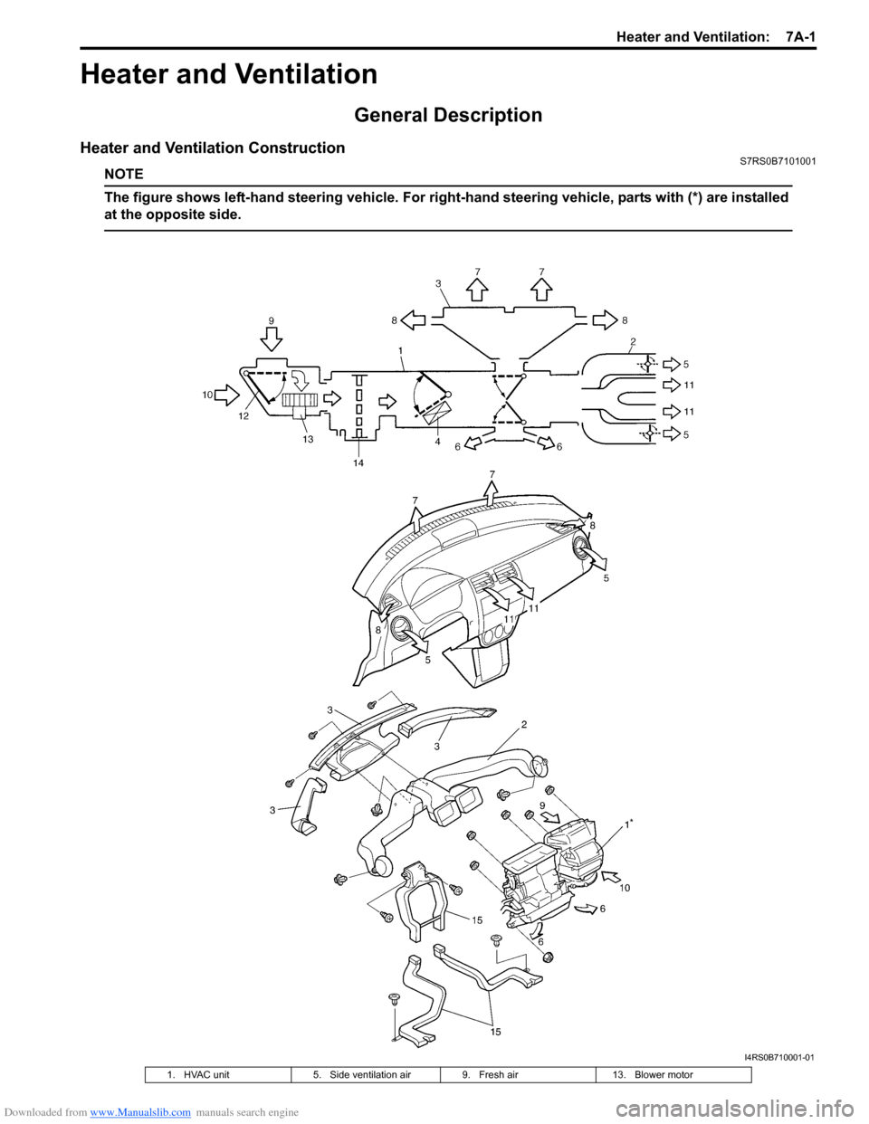
Heater and Ventilation ConstructionS7RS0B7101001
NOTE
The figure shows left-hand steering vehicle. For right-hand steering vehicle, parts with (*) are installed
at the opposite side.
I4RS0B710001-01
1. HVAC unit 5. Side ventilation air 9. Fresh air 13. Blower motor
Page 943 of 1496
Downloaded from www.Manualslib.com manuals search engine Heater and Ventilation: 7A-7
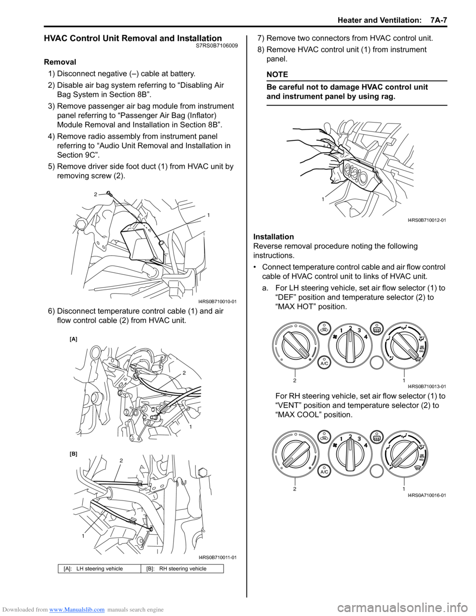
HVAC Control Unit Removal and InstallationS7RS0B7106009
Removal1) Disconnect negative (–) cable at battery.
2) Disable air bag system referring to “Disabling Air Bag System in Section 8B”.
3) Remove passenger air bag module from instrument panel referring to “Passenger Air Bag (Inflator)
Module Removal and Installation in Section 8B”.
4) Remove radio assembly from instrument panel referring to “Audio Unit Re moval and Installation in
Section 9C”.
5) Remove driver side foot duct (1) from HVAC unit by removing screw (2).
6) Disconnect temperature control cable (1) and air flow control cable (2) from HVAC unit. 7) Remove two connectors from HVAC control unit.
8) Remove HVAC control unit (1) from instrument
panel.
NOTE
Be careful not to damage HVAC control unit
and instrument panel by using rag.
Installation
Reverse removal procedure noting the following
instructions.
• Connect temperature control cable and air flow control
cable of HVAC control unit to links of HVAC unit.
a. For LH steering vehicle, set air flow selector (1) to “DEF” position and temperature selector (2) to
“MAX HOT” position.
For RH steering vehicle, set air flow selector (1) to
“VENT” position and temperature selector (2) to
“MAX COOL” position.
[A]: LH steering vehicle [B]: RH steering vehicle
2
1
I4RS0B710010-01
2
1
1
2
[B] [A]
I4RS0B710011-01
1
I4RS0B710012-01
12I4RS0B710013-01
12I4RS0A710016-01
Page 944 of 1496
Downloaded from www.Manualslib.com manuals search engine 7A-8 Heater and Ventilation:
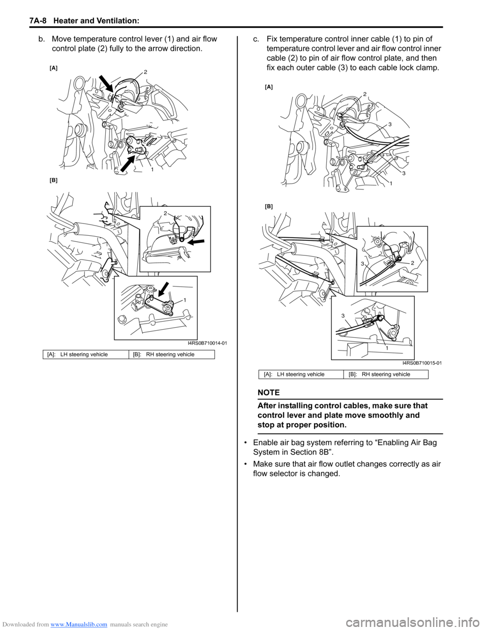
b. Move temperature control lever (1) and air flow control plate (2) fully to the arrow direction. c. Fix temperature control inner cable (1) to pin of
temperature control lever and air flow control inner
cable (2) to pin of air fl ow control plate, and then
fix each outer cable (3) to each cable lock clamp.
NOTE
After installing control cables, make sure that
control lever and plate move smoothly and
stop at proper position.
• Enable air bag system referring to “Enabling Air Bag System in Section 8B”.
• Make sure that air flow outlet changes correctly as air flow selector is changed.
[A]: LH steering vehicle [B]: RH steering vehicle
1
2
[A]
[B]
1
2
I4RS0B710014-01
[A]: LH steering vehicle [B]: RH steering vehicle
1
2
[B] [A] 3
3
1
3
23
I4RS0B710015-01