Shock absorber SUZUKI SWIFT 2005 2.G Service User Guide
[x] Cancel search | Manufacturer: SUZUKI, Model Year: 2005, Model line: SWIFT, Model: SUZUKI SWIFT 2005 2.GPages: 1496, PDF Size: 34.44 MB
Page 463 of 1496

Downloaded from www.Manualslib.com manuals search engine Rear Suspension: 2C-9
12) Fill reservoir with brake fluid and bleed brake system. For bleeding operation, see “Air Bleeding of
Brake System in Section 4A”.
13) Install wheel and tighten wheel nuts to specified torque.
Tightening torque
Wheel nut: 85 N·m (8.5 kgf-m, 61.5 lb-ft)
14) Adjust parking brake cable. For adjustment, refer to “Parking Brake Inspection and Adjustment in Section
4D”.
15) Lower hoist and bounce vehicle up and down several times to stabilize suspension.
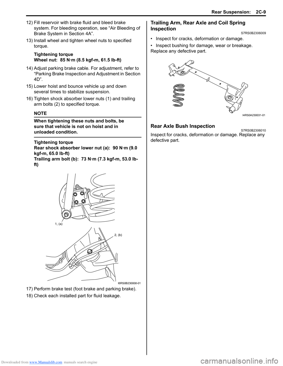
16) Tighten shock ab sorber lower nuts (1) and trailing
arm bolts (2) to specified torque.
NOTE
When tightening these nuts and bolts, be
sure that vehicle is not on hoist and in
unloaded condition.
Tightening torque
Rear shock absorber lower nut (a): 90 N·m (9.0
kgf-m, 65.0 lb-ft)
Trailing arm bolt (b): 73 N·m (7.3 kgf-m, 53.0 lb-
ft)
17) Perform brake test (foot brake and parking brake).
18) Check each installed part for fluid leakage.
Trailing Arm, Rear Axle and Coil Spring
Inspection
S7RS0B2306009
• Inspect for cracks, deformation or damage.
• Inspect bushing for damage, wear or breakage.
Replace any defective part.
Rear Axle Bush InspectionS7RS0B2306010
Inspect for cracks, deformation or damage. Replace any
defective part.
1, (a)
2, (b)
I6RS0B230008-01
I4RS0A230031-01
Page 467 of 1496

Downloaded from www.Manualslib.com manuals search engine Rear Suspension: 2C-13
Spindle InspectionS7RS0B2306015
• Inspect for cracks, deformation or damage.Replace any defective part.
Rear Suspension Fasteners InspectionS7RS0B2306016
Check each bolt and nut fastening suspension parts for
tightness. Tighten loose one, if any, to specified torque
referring to the figure in “Rear Suspension Construction”.
Specifications
Tightening Torque SpecificationsS7RS0B2307001
NOTE
The specified tightening torque is also described in the following.
“Rear Suspension Construction”
“Rear Wheel Hub Components”
Reference:
For the tightening torque of fastener not specified in this section, refer to “Fasteners Information in Section 0A”.
Special Tools and Equipment
Special ToolS7RS0B2308001
I6RS0B230017-01
Fastening part Tightening torque
Note
N ⋅mkgf-mlb-ft
Wheel nut 85 8.5 61.5 �) / �) / �) / �) / �)
Rear shock absorber upper nut 28 2.8 20.0 �)
Rear shock absorber lower nut 90 9.0 65.0 �) / �) / �)
Wheel speed sensor bolt 11 1.1 8.0 �) / �)
Brake pipe flare nut 16 1.6 11.5 �) / �)
Parking brake cable clamp bolt 11 1.1 8.0 �)
Trailing arm bolt 73 7.3 53.0 �)
Rear axle nut 175 17.5 126.5 �)
Rear spindle bolt 88 8.8 64.0 �)
09942–1551109943–17912
Sliding hammer Wheel hub remover
�)�)
Page 506 of 1496

Downloaded from www.Manualslib.com manuals search engine 4A-8 Brake Control System and Diagnosis:
Excessive Pedal Travel InspectionS7RS0B4106003
1) Start engine.
2) Depress brake pedal a few times.
3) With brake pedal depressed with approximately 300 N (30 kg, 66 lbs) load, measure brake pedal to wall
(dash panel silencer) clearance “a”. If clearance “a”
is less than specification, the most possible cause is
air in lines. Should clearance “a” remain less than
specification even after bleeding of system, other
possible infrequent cause is booster push rod length
out of adjustment.
• Bleed brake system. Refer to “Air Bleeding of Brake System”.
Brake arm pedal to wall clearance “a”
When pedal depressed at 300 N (30 kg, 66 lbs):
over 75 mm (2.95 in.)
Brake Fluid Level InspectionS7RS0B4106004
1) Check master cylinder, reservoir and reservoir hose (if equipped) for crack, damage and brake fluid
leakage. If any faulty condition exists, correct or
replace.
2) Check that brake fluid level is between MAX and MIN marks on reservoir.
NOTE
Be sure to use particular brake fluid either as
indicated on reservoir cap of that vehicle or
recommended in owner’s manual which
comes along with that vehicle. Use of any
other fluid is strictly prohibited.
Fluid level should be between MIN and MAX
lines marked on reservoir.
When brake warning lamp lights sometimes
during driving, replenis h fluid to MAX level.
When fluid decreases quickly, inspect brake
system for leakage. Correct leaky points and
then refill to specified level.
CAUTION!
Do not use shock absorber fluid or any other
fluid which contains mineral oil. Do not use a
container which has been used for mineral oil
or a container which is wet from water.
Mineral oil will cause swelling and distortion
of rubber parts in hydraulic brake system and
water mixed into brake fluid will lower fluid
boiling point. Keep all fluid containers
capped to prevent contamination.
Stop Light Switch AdjustmentS7RS0B4106005
Adjustment should be made as follows. Pull up brake
pedal toward you and while holding it there, adjust
switch position so that clea rance between end of thread
and brake pedal is as specified. Then lock it by turning
clockwise.
Clearance between brake pedal and stop light switch
“a”: 1.2 – 2.2 mm (0.05 – 0.08 in.)
I6RS0C410005-02
I4RS0B410006-01
I4RS0A410007-01
Page 1388 of 1496

Downloaded from www.Manualslib.com manuals search engine 9L-1 Paint / Coatings:
Body, Cab and Accessories
Paint / Coatings
General Description
Anti-Corrosion Treatment ConstructionS7RS0B9C01001
WARNING!
Standard shop practices, particularly eye protection, should be followed during the performance of the
following operations to avoid personal injury.
As rust proof treatment, steel sheets are given corrosion resistance on the interior and/or exterior.
These corrosion resistance steel sheet materials ar e called one of two-side galvanized steel sheets.
It is for the sake of rust protection that these materials are selected and given a variety of treatments as described
blow.
• Steel sheets are treated with cathodic electro primer which is excellent in corrosion resistance.
• Rust proof wax coatings are applied to door and side sill insides where mois ture is liable to stay.
• Vinyl coating is applied to body underside and wheel housing inside.
• Sealer is applied to door hem, engine compartment steel sheet-to-steel sheet joint, and the like portions to prevent water penetration and resulting in rust occurrence.
In panel replacement or collision damage repair, leaving the relevant area untreated as it is in any operation which
does disturb the rust proof treatment will cause corrosion to th at area. Therefore, it is the essential function of any
repair operation to correctly recoat t he related surfaces of the relevant area.
All the metal panels are coated with metal conditioners an d primer coating during vehicle production. Following the
repair and/or replacement parts installation, every access ible bare metal surface should be cleaned and coated with
rust proof primer. Perform this operation prior to the application of sealer and rust proof wax coating.
Sealer is applied to the spec ific joints of a vehicle during production. The sealer is intended to prevent dust from
entering the vehicle and serves also as an anti corrosion barrier. The sealer is applied to the door and hood hem areas
and between panels. Correct and reseal the originally sealed joints if damaged. Reseal the attaching joints of a new
replacement panel and reseal the hem area of a replacement door or hood.
Use a quality sealer to seal the flanged joints, overlap joints and seams. The sealer must have flexible characteristics
and paint ability after it’s applied to repair areas.
For the sealer to fill open joints, use caulking material. Select a sealer in conf ormance with the place and purpose of a
specific use. Observe the ma nufacturer’s label-stand instructions when using the sealer.
In many cases, repaired places require color painting. When this is required, follow the ordinary techniques specified
for the finish preparation, color painting and undercoating build-up.
Rust proof wax, a penetrative compound, is applied to the metal-to-metal surfaces (door and side sill insides) where it
is difficult to use ordinary undercoating material for coating. Therefore, when selecting the rust proof wax, it may be the
penetrative type.
During the undercoating (vinyl coating) application, care should be taken that sealer is not applied to the engine-
related parts and shock absorber mounting or rotating parts. Following the under coating, make sure that body drain
holes are kept open.
The sequence of the application steps of the anti-corrosion materials are as follows:
1) Clean and prepare the metal surface.
2) Apply primer.
3) Apply sealer (all joints sealed originally).
4) Apply color in areas where color is required such as hem flanges, exposed joints and under body components.
5) Apply anti corrosion compound (penetrative wax).
6) Apply undercoating (rust proof material).