height SUZUKI SWIFT 2005 2.G Service User Guide
[x] Cancel search | Manufacturer: SUZUKI, Model Year: 2005, Model line: SWIFT, Model: SUZUKI SWIFT 2005 2.GPages: 1496, PDF Size: 34.44 MB
Page 503 of 1496
Downloaded from www.Manualslib.com manuals search engine Brake Control System and Diagnosis: 4A-5
If deterioration of rubber is evident, disassemble all
hydraulic parts and wash with alcohol. Dry these parts
with compressed air before assembly to keep alcohol out
of the system. Replace all rubber parts in the system,
including hoses. Also, when working on the brake
mechanisms, check for fluid on the linings.
If excessive fluid is found, replace the pads. If master cylinder piston seals
are satisfactory, check for
leakage or excessive heat co nditions. If leakage is not
found, drain fluid, flush with brake fluid, refill and bleed
system.
The system must be flushed if there is any doubt as to
the grade of fluid in the system or if fluid has been used
which contained parts that have been subjected to
contaminated fluid.
Brakes Symptom DiagnosisS7RS0B4104002
Condition Possible cause Correction / Reference Item
Not enough braking force Brake oil leakage from brake lines Locate leaking point and repair.
Brake disc or brake pad stained with oil Clean or replace.
Overheated brakes Determine cause and repair.
Badly worn brake pad Replace.
Malfunctioning caliper assembly Repair or replace.
Malfunctioning brake booster Check system and replace assembly.
Malfunctioning brake master cylinder Check system and replace as necessary.
Air in system Bleed system.
Malfunctioning ABS (ESP ®). Check system and replace as necessary.
Brake pull (Brakes not
working in unison) Brake pad and disc are wet with water or
stained with oil in some brakes Clean or replace.
Disc is out of round in some brakes Replace.
Tires are inflated unequally Inflate equally.
Disturbed front wheel alignment Adjust as prescribed.
Unmatched tires on same axle Tires with approximately the same amount of
tread should be used on the same axle.
Restricted brake pipes or hoses Check for soft hoses and damaged lines.
Replace with new hoses and new double-
walled steel brake tubing.
Malfunctioning caliper assembly Caliper should slide.
Check for stuck or sluggish pistons and proper
lubrication of caliper slide pin.
Loose suspension parts Check all suspension mountings.
Loose calipers Check and torque bolts to specifications.
Noise (High pitched
squeak without brake
applied) Contact wear indicator to brake disc
Replace brake pads.
Worn brake pad Replace brake pads.
Excessive pedal travel
(Pedal stroke too large) Partial brake system failure
Check brake systems and repair as necessary.
Brake fluid leaking Repair the leaking point and bleed air.
Air in system (soft / spongy pedal) Bleed system.
Brake locked Malfunctioning ABS (ESP®) Check system referri ng to “ABS Check in
Section 4E” or “Electronic Stability Program
System Check in Section 4F”.
Dragging brakes (A very
light drag is present in all
brakes immediately after
pedal is released.) Master cylinder pistons not returning
correctly
Replace master cylinder.
Restricted brake pipes or hoses Check for soft hoses or damaged pipes and
replace with new hoses and/or new brake
piping.
Incorrect parking brake adjustment on
rear brakes Check and adjust to correct specifications.
Weakened or broken return springs in
rear brakes. Replace.
Sluggish parking brake cables or linkage Repair or replace.
Brake caliper piston sticking Repair as necessary.
Badly worn piston seal in caliper Replace piston seal.
Improper brake pedal free height Check brake pedal free height.
Page 505 of 1496
Downloaded from www.Manualslib.com manuals search engine Brake Control System and Diagnosis: 4A-7
Repair Instructions
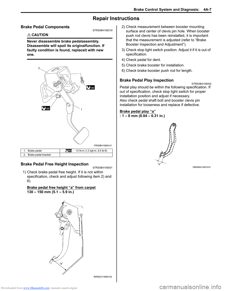
Brake Pedal ComponentsS7RS0B4106019
CAUTION!
Never disassemble brake pedalassembly.
Disassemble will spoil its originalfunction. If
faulty condition is found, replaceit with new
one.
Brake Pedal Free Height InspectionS7RS0B4106001
1) Check brake pedal free height. If it is not within specification, check and ad just following item 2) and
6).
Brake pedal free height “a” from carpet
130 – 150 mm (5.1 – 5.9 in.) 2) Check measurement between booster mounting
surface and center of clevis pin hole. When booster
push rod clevis has been reinstalled, it is important
that the measurement is adj usted (refer to “Brake
Booster Inspection and Adjustment”).
3) Check stop light switch position . Adjust it if it is out of
specification.
4) Check pedal for dent.
5) Check brake booster for installation.
6) Check brake booster push rod for length.
Brake Pedal Play InspectionS7RS0B4106002
Pedal play should be within the following specification. If
out of specification, check stop light switch for proper
installation position and adjust if necessary.
Also check pedal shaft bolt and booster clevis pin
installation for looseness and replace if defective.
Brake pedal play
“a”
: 1 – 8 mm (0.04 – 0.31 in.)
1. Brake pedal : 13 N⋅m (1,3 kgf-m, 9.5 lb-ft)
2. Brake pedal bracket
(a) 1
2
(a)
I7RS0B410002-01
I6RS0C410004-02
“a”I3RH0A410010-01
Page 515 of 1496
Downloaded from www.Manualslib.com manuals search engine Brake Control System and Diagnosis: 4A-17
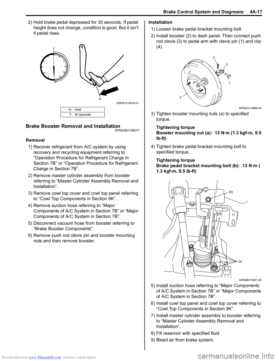
2) Hold brake pedal depressed for 30 seconds. If pedal height does not change, condition is good. But it isn’t
if pedal rises.
Brake Booster Removal and InstallationS7RS0B4106017
Removal
1) Recover refrigerant from A/C system by using recovery and recycling equipment referring to
“Operation Procedure for Refrigerant Charge in
Section 7B” or “Operation Procedure for Refrigerant
Charge in Section 7B”.
2) Remove master cylinder assembly from booster referring to “Master Cylin der Assembly Removal and
Installation”.
3) Remove cowl top cover and cowl top panel referring to “Cowl Top Components in Section 9K”.
4) Remove suction hose referring to “Major Components of A/C System in Section 7B” or “Major
Components of A/C System in Section 7B”.
5) Disconnect vacuum hose from booster referring to “Brake Booster Components”.
6) Remove push rod clevis pin and booster mounting nuts and then remove booster. Installation
1) Loosen brake pedal bracket mounting bolt.
2) Install booster (2) to dash panel. Then connect push rod clevis (3) to pedal arm with clevis pin (1) and clip
(4).
3) Tighten booster mounting nuts (a) to specified torque.
Tightening torque
Booster mounting nut (a): 13 N·m (1.3 kgf-m, 9.5
lb-ft)
4) Tighten brake pedal bracket mounting bolt to specified torque.
Tightening torque
Brake pedal bracket mounting bolt (b): 13 N·m (
1.3 kgf-m, 9.5 lb-ft)
5) Install suction hose referring to “Major Components of A/C System in Section 7B” or “Major Components
of A/C System in Section 7B”.
6) Install cowl top panel and cowl top cover referring to
“Cowl Top Components in Section 9K”.
7) Install master cylinder assembly to booster referring to “Master Cylinder Assembly Removal and
Installation”.
8) Fill reservoir with specified fluid.
9) Bleed air from brake system.
H: Hold
T: 30 seconds
I2RH01410010-01
1
2 4
3
I6RS0C410006-02
(b)
(a)
I4RS0B410021-02
Page 516 of 1496
Downloaded from www.Manualslib.com manuals search engine 4A-18 Brake Control System and Diagnosis:
10) Check pedal height and play referring to “Brake Pedal Free Height Inspection” and “Brake Pedal
Play Inspection”.
11) Check each installed part for fluid leakage and perform brake test.
12) Evacuate and charge refrigerant by referring to “Evacuating of A/C Syst em” and “Procedure of
Charging” under “Operation Procedure for
Refrigerant Charge in Section 7B” or “Operation
Procedure for Refrigerant Charge in Section 7B”.
Brake Booster Inspection and AdjustmentS7RS0B4106018
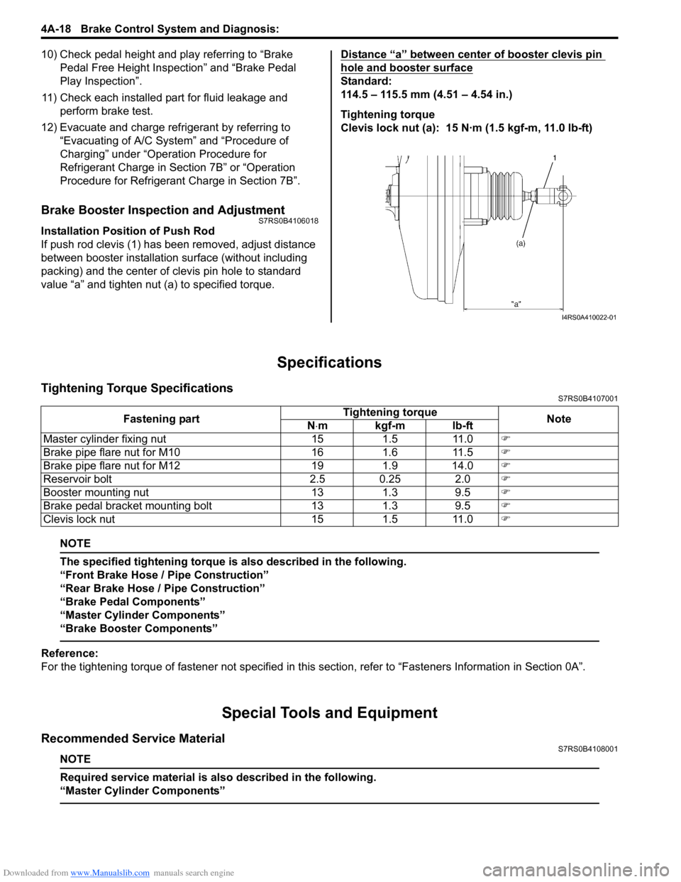
Installation Position of Push Rod
If push rod clevis (1) has b een removed, adjust distance
between booster installation surface (without including
packing) and the center of clevis pin hole to standard
value “a” and tighten nut (a) to specified torque. Distance “a” between center of booster clevis pin
hole and booster surface
Standard:
114.5 – 115.5 mm (4.51 – 4.54 in.)
Tightening torque
Clevis lock nut (a): 15 N·m (1.5 kgf-m, 11.0 lb-ft)
Specifications
Tightening Torque SpecificationsS7RS0B4107001
NOTE
The specified tightening torque is also described in the following.
“Front Brake Hose / Pipe Construction”
“Rear Brake Hose / Pipe Construction”
“Brake Pedal Components”
“Master Cylinder Components”
“Brake Booster Components”
Reference:
For the tightening torque of fastener not specified in this
section, refer to “Fasteners Information in Section 0A”.
Special Tools and Equipment
Recommended Service MaterialS7RS0B4108001
NOTE
Required service material is also described in the following.
“Master Cylinder Components”
I4RS0A410022-01
Fastening part Tightening torque
Note
N ⋅mkgf-mlb-ft
Master cylinder fixing nut 15 1.5 11.0 �)
Brake pipe flare nut for M10 16 1.6 11.5 �)
Brake pipe flare nut for M12 19 1.9 14.0 �)
Reservoir bolt 2.5 0.25 2.0 �)
Booster mounting nut 13 1.3 9.5 �)
Brake pedal bracket mounting bolt 13 1.3 9.5 �)
Clevis lock nut 15 1.5 11.0 �)
Page 834 of 1496
Downloaded from www.Manualslib.com manuals search engine 5B-20 Manual Transmission/Transaxle:
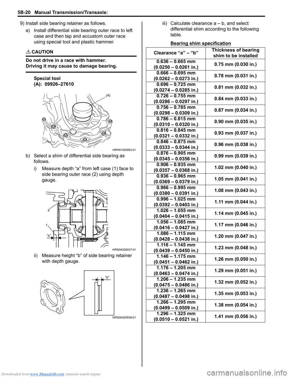
9) Install side bearing retainer as follows.a) Install differential side bearing outer race to left case and then tap and accustom outer race
using special tool and plastic hammer.
CAUTION!
Do not drive in a race with hammer.
Driving it may cause to damage bearing.
Special tool
(A): 09926–27610
b) Select a shim of differential side bearing as follows.
i) Measure depth “a” from left case (1) face to side bearing outer race (2) using depth
gauge.
ii) Measure height “b” of side bearing retainer with depth gauge. iii) Calculate clearance a – b, and select
differential shim acco rding to the following
table.
Bearing shim specification
(A)
I4RH01520053-01
I4RS0A520037-01
“b”
I4RS0A520038-01
Clearance “a” – “b” Thickness of bearing
shim to be installed
0.636 – 0.665 mm
(0.0250 – 0.0261 in.) 0.75 mm (0.030 in.)
0.666 – 0.695 mm
(0.0262 – 0.0273 in.) 0.78 mm (0.031 in.)
0.696 – 0.725 mm
(0.0274 – 0.0285 in.) 0.81 mm (0.032 in.)
0.726 – 0.755 mm
(0.0286 – 0.0297 in.) 0.84 mm (0.033 in.)
0.756 – 0.785 mm
(0.0298 – 0.0309 in.) 0.87 mm (0.034 in.)
0.786 – 0.815 mm
(0.0310 – 0.0320 in.) 0.90 mm (0.035 in.)
0.816 – 0.845 mm
(0.0321 – 0.0332 in.) 0.93 mm (0.037 in.)
0.846 – 0.875 mm
(0.0333 – 0.0344 in.) 0.96 mm (0.038 in.)
0.876 – 0.905 mm
(0.0345 – 0.0356 in.) 0.99 mm (0.039 in.)
0.906 – 0.935 mm
(0.0357 – 0.0368 in.) 1.02 mm (0.040 in.)
0.936 – 0.965 mm
(0.0369 – 0.0379 in.) 1.05 mm (0.041 in.)
0.966 – 0.995 mm
(0.0380 – 0.0391 in.) 1.08 mm (0.043 in.)
0.996 – 1.025 mm
(0.0392 – 0.0403 in.) 1.11 mm (0.044 in.)
1.026 – 1.055 mm
(0.0404 – 0.0415 in.) 1.14 mm (0.045 in.)
1.056 – 1.085 mm
(0.0416 – 0.0427 in.) 1.17 mm (0.046 in.)
1.086 – 1.115 mm
(0.0428 – 0.0438 in.) 1.20 mm (0.047 in.)
1.116 – 1.145 mm
(0.0439 – 0.0450 in.) 1.23 mm (0.048 in.)
1.146 – 1.175 mm
(0.0451 – 0.0462 in.) 1.26 mm (0.050 in.)
1.176 – 1.205 mm
(0.0463 – 0.0474 in.) 1.29 mm (0.051 in.)
1.206 – 1.235 mm
(0.0475 – 0.0486 in.) 1.32 mm (0.052 in.)
1.236 – 1.265 mm
(0.0487 – 0.0498 in.) 1.35 mm (0.053 in.)
1.266 – 1.295 mm
(0.0499 – 0.0509 in.) 1.38 mm (0.054 in.)
1.296 – 1.325 mm
(0.0510 – 0.0521 in.) 1.41 mm (0.056 in.)
Page 1035 of 1496
Downloaded from www.Manualslib.com manuals search engine Seat Belts: 8A-4
Front Seat Belt Removal and InstallationS7RS0B8106002
WARNING!
• Never attempt to disassemble or repair the seat belt pretensioner (retractor
assembly). If any abnormality is found, be
sure to replace it with new one as an
assembly.
• Be sure to read “Precautions on Service and Diagnosis of Seat Belt” before starting
to work and observe every precaution
during work. Ne glecting them may result in
personal injury or una ctivation of the seat
belt pretensioner when necessary.
Removal
1) Disconnect negative (–) cable at battery.
2) Disable air bag system. Refer to “Disabling Air Bag System in Section 8B”.
3) Remove center pillar lower trim.
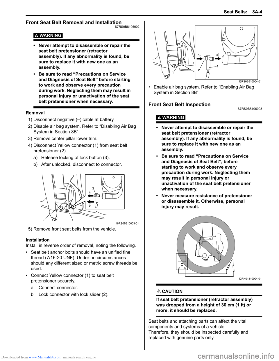
4) Disconnect Yellow connector (1) from seat belt pretensioner (2).
a) Release locking of lock button (3).
b) After unlocked, disconnect to connector.
5) Remove front seat belts from the vehicle.
Installation
Install in reverse order of removal, noting the following.
• Seat belt anchor bolts should have an unified fine thread (7/16-20 UNF). Under no circumstances
should any different sized or metric screw threads be
used.
• Connect Yellow connector (1) to seat belt pretensioner securely.
a. Connect connector.
b. Lock connector with lock slider (2). • Enable air bag system. Refer to “Enabling Air Bag
System in Section 8B”.
Front Seat Belt InspectionS7RS0B8106003
WARNING!
• Never attempt to disassemble or repair the seat belt pretensioner (retractor
assembly). If any abnormality is found, be
sure to replace it with new one as an
assembly.
• Be sure to read “Precautions on Service and Diagnosis of Seat Belt”, before
starting to work and observe every
precaution during work. Neglecting them
may result in personal injury or
unactivation of the seat belt pretensioner
when necessary.
• Never measure resistance of pretensioner or disassemble it. Otherwise, personal
injury may result.
CAUTION!
If seat belt pretensioner (retractor assembly)
was dropped from a height of 30 cm (1 ft) or
more, it should be replaced.
Seat belts and attaching parts can affect the vital
components and systems of a vehicle.
Therefore, they should be inspected carefully and
replaced with genuine parts only.
a
b
21 3I6RS0B810003-01
1
1
2
b)
a)
I6RS0B810004-01
I2RH01810004-01
Page 1039 of 1496
Downloaded from www.Manualslib.com manuals search engine Air Bag System: 8B-1
Restraint
Air Bag System
Precautions
Precautions on Service and Diagnosis of Air
Bag System
S7RS0B8200001
WARNING!
• If the air bag system and another vehicle system both need repair, SUZUKI
recommends that the air bag system be
repaired first, to help avoid unintended air
bag system activation.
• Do not modify the steering wheel, dashboard, both front seat or any other on
or around air bag system components.
Modifications can adversely affect air bag
system performance and lead to injury.
• Be sure to follow the procedures described in this section. Failure to follow
procedures could result in possible air bag
system activation, personal injury or
unneeded air bag system repairs.
• WARNING / CAUTION labels are attached on each
part of air bag system components (SDM, air bag
(inflator) modules and seat belt pretensioners). Be
sure to follow the instructions.
• Many of service procedures require disconnection of
“A/BAG” fuse and air bag (inflator) module(s) (driver,
passenger, side of both si des and curtain of both
sides) from initiator circuit to avoid an accidental
deployment.
• Do not apply power to the air bag system unless all components are connected or a diagnostic flow
requests it, as this will set a DTC.
• The “Air Bag Diagnostic S ystem Check” must be the
starting point of any air bag diagnostics. The “Air Bag
Diagnostic System Check” will verify proper “AIR
BAG” warning right operatio n and will lead you to the
correct flow to diagnose any air bag malfunctions.
Bypassing these procedures may result in extended
diagnostic time, incorrect diagnosis, and incorrect
parts replacements. • Never use air bag component parts from another
vehicle.
• If the vehicle will be exposed to temperatures over 93
° C (200 °F) (for example, during a paint baking
process), remove the air bag system components
beforehand to avoid component damage or
unintended system activation.
• When handling the air bag (inflator) modules (driver, passenger, side of both si des and curtain of both
sides), seat belt pretensio ners (driver and passenger),
SDM, forward-sensor or side-sensor, be careful not to
drop it or apply an impact to it. If an excessive impact
was applied (e.g., SDM, forward-sensor and side-
sensor are dropped, air bag (inflator) module is
dropped from a height of 90 cm (3 ft) or more, seat
belt pretensioner (retractor assembly) is dropped from
a height of 30 cm (1 ft) or more), never attempt
disassembly or repair but replace it with a new one.
• When using electric welding, be sure to disconnect air bag (inflator) module connectors (driver, passenger,
side of both sides and curtain of both sides) and seat
belt pretensioner connectors (driver and passenger)
respectively.
• When applying paint around the air bag system related parts, use care so that the harness or
connector will not be expo sed to the paint mist.
• Never expose air bag system component parts directly to hot air (drying or baking the vehicle after
painting) or flames.
WARNING!
When performing service on or around air
bag system components or air bag wiring,
follow the procedures listed in “Disabling Air
Bag System” to temporarily disable the air
bag system.
Failure to follow procedures could result in
possible air bag system activation, personal
injury or unneeded air bag system repairs.
Page 1041 of 1496
Downloaded from www.Manualslib.com manuals search engine Air Bag System: 8B-3
• Never attempt disassembly of the air bag (inflator) modules.
• If any abnormality is found, be sure to replace it with
new one as an assembly.
• When an abnormality is noted as existing in the live (undeployed) air bag (inflator) module, be sure to
deploy it before discarding it.
• When grease, cleaning agent, oil, water, etc., got on the air bag (inflator) modules (driver, passenger, side
of both sides and curtain of both sides), wipe it off
immediately with a dry cloth.
• If air bag (inflator) module was dropped from a height of 90 cm (3 ft) or more, it should be replaced with a
new one as an assembly.
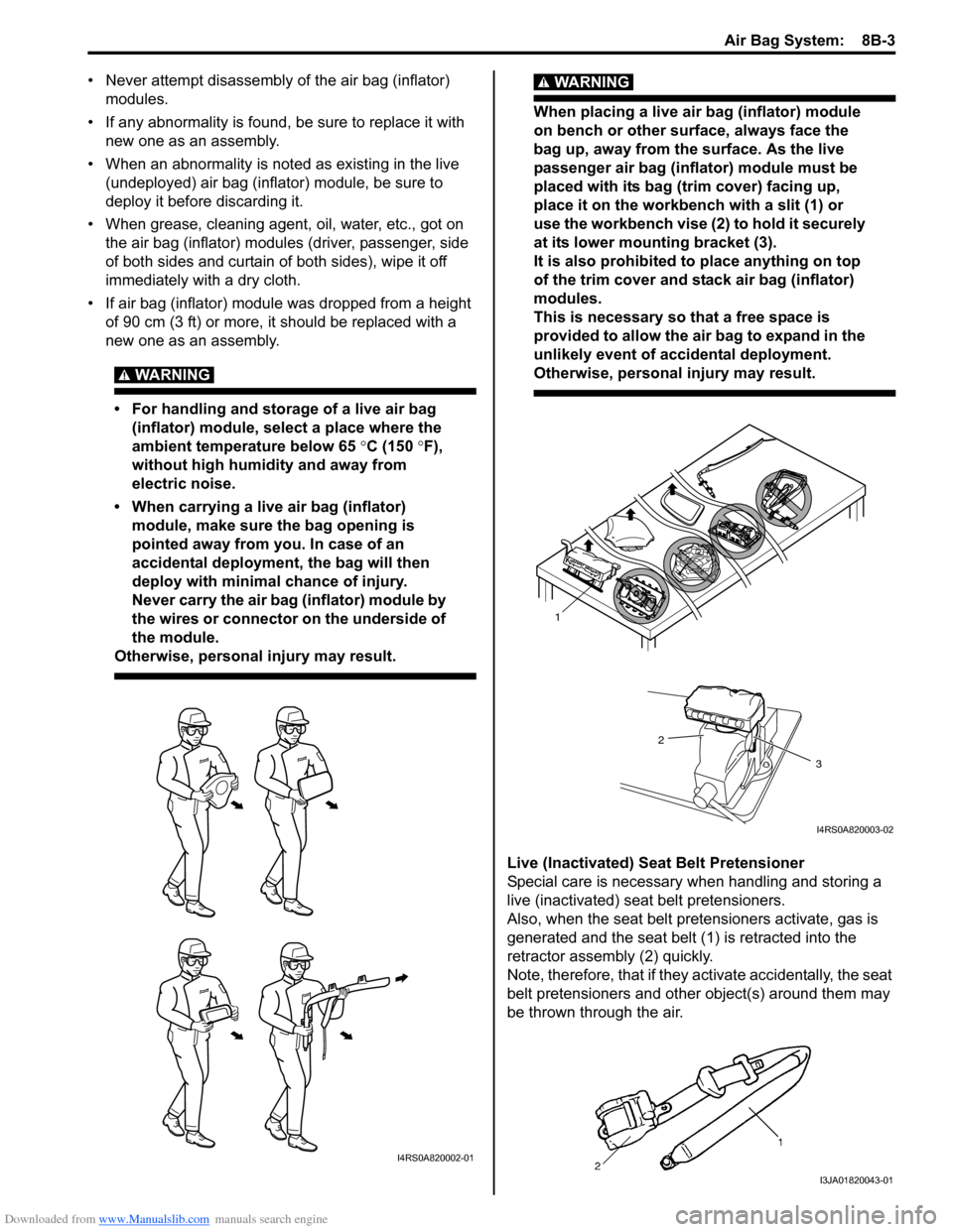
WARNING!
• For handling and storage of a live air bag (inflator) module, select a place where the
ambient temperature below 65 °C (150 ° F),
without high humidity and away from
electric noise.
• When carrying a live air bag (inflator) module, make sure the bag opening is
pointed away from you. In case of an
accidental deployment, the bag will then
deploy with minimal chance of injury.
Never carry the air bag (inflator) module by
the wires or connector on the underside of
the module.
Otherwise, personal injury may result.
WARNING!
When placing a live air bag (inflator) module
on bench or other surface, always face the
bag up, away from the surface. As the live
passenger air bag (inflator) module must be
placed with its bag (trim cover) facing up,
place it on the workbench with a slit (1) or
use the workbench vise (2) to hold it securely
at its lower mounting bracket (3).
It is also prohibited to place anything on top
of the trim cover and stack air bag (inflator)
modules.
This is necessary so that a free space is
provided to allow the air bag to expand in the
unlikely event of accidental deployment.
Otherwise, personal injury may result.
Live (Inactivated) Seat Belt Pretensioner
Special care is necessary when handling and storing a
live (inactivated) seat belt pretensioners.
Also, when the seat belt pretensioners activate, gas is
generated and the seat belt (1) is retracted into the
retractor assembly (2) quickly.
Note, therefore, that if they activate accidentally, the seat
belt pretensioners and other object(s) around them may
be thrown through the air.
I4RS0A820002-01
1
2
3
I4RS0A820003-02
I3JA01820043-01
Page 1042 of 1496
Downloaded from www.Manualslib.com manuals search engine 8B-4 Air Bag System:
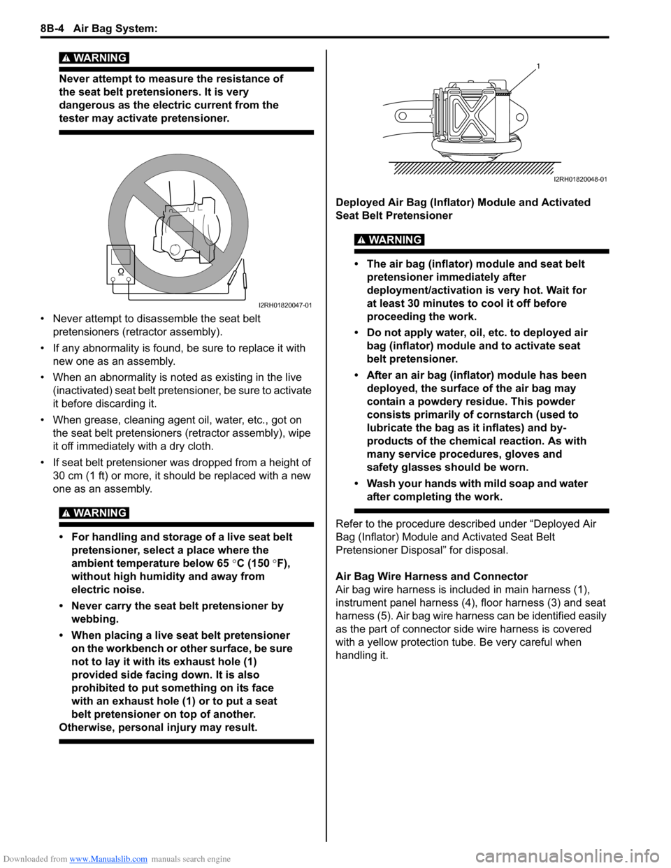
WARNING!
Never attempt to measure the resistance of
the seat belt pretensioners. It is very
dangerous as the electric current from the
tester may activate pretensioner.
• Never attempt to disassemble the seat belt
pretensioners (retractor assembly).
• If any abnormality is found, be sure to replace it with
new one as an assembly.
• When an abnormality is noted as existing in the live (inactivated) seat belt preten sioner, be sure to activate
it before discarding it.
• When grease, cleaning agent oil, water, etc., got on the seat belt pretensioners (r etractor assembly), wipe
it off immediately with a dry cloth.
• If seat belt pretensioner was dropped from a height of 30 cm (1 ft) or more, it should be replaced with a new
one as an assembly.
WARNING!
• For handling and storage of a live seat belt pretensioner, select a place where the
ambient temperature below 65 °C (150 ° F),
without high humidity and away from
electric noise.
• Never carry the seat belt pretensioner by webbing.
• When placing a live seat belt pretensioner on the workbench or other surface, be sure
not to lay it with its exhaust hole (1)
provided side facing down. It is also
prohibited to put something on its face
with an exhaust hole (1) or to put a seat
belt pretensioner on top of another.
Otherwise, personal injury may result.
Deployed Air Bag (Inflator) Module and Activated
Seat Belt Pretensioner
WARNING!
• The air bag (inflator) module and seat belt
pretensioner immediately after
deployment/activation is very hot. Wait for
at least 30 minutes to cool it off before
proceeding the work.
• Do not apply water, oil, etc. to deployed air bag (inflator) module and to activate seat
belt pretensioner.
• After an air bag (inflator) module has been deployed, the surface of the air bag may
contain a powdery residue. This powder
consists primarily of cornstarch (used to
lubricate the bag as it inflates) and by-
products of the chemical reaction. As with
many service procedures, gloves and
safety glasses should be worn.
• Wash your hands with mild soap and water after completing the work.
Refer to the procedure described under “Deployed Air
Bag (Inflator) Module and Activated Seat Belt
Pretensioner Disposal” for disposal.
Air Bag Wire Harness and Connector
Air bag wire harness is includ ed in main harness (1),
instrument panel harness (4), floor harness (3) and seat
harness (5). Air bag wire harness can be identified easily
as the part of connector side wire harness is covered
with a yellow protection tube. Be very careful when
handling it.
I2RH01820047-01
1
I2RH01820048-01
Page 1141 of 1496
Downloaded from www.Manualslib.com manuals search engine Air Bag System: 8B-103
Driver Air Bag (Inflator) Module InspectionS7RS0B8206006
WARNING!
Never disassemble air bag (inflator) module
or measure its resistance. Otherwise,
personal injury may result.
CAUTION!
If air bag (inflator) module was dropped from
a height of 90 cm (3 ft) or more, it should be
replaced.
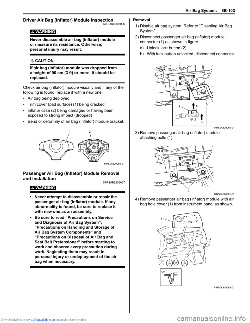
Check air bag (inflator) module visually and if any of the
following is found, replace it with a new one.
• Air bag being deployed
• Trim cover (pad surface) (1) being cracked
• Inflator case (2) being damaged or having been exposed to strong impact (dropped)
• Bend or deformity of air bag (inflator) module bracket.
Passenger Air Bag (Inflator) Module Removal
and Installation
S7RS0B8206007
WARNING!
• Never attempt to disassemble or repair the passenger air bag (inflator) module. If any
abnormality is found, be sure to replace it
with new one as an assembly.
• Be sure to read “Precautions on Service and Diagnosis of Air Bag System”,
“Precautions on Handling and Storage of
Air Bag System Components” and
“Precautions on Disposal of Air Bag and
Seat Belt Pretensioner” before starting to
work and observe every precaution during
work. Neglecting them may result in
personal injury or undeployment of the air
bag when necessary.
Removal
1) Disable air bag system. Re fer to “Disabling Air Bag
System”.
2) Disconnect passenger air bag (inflator) module connector (1) as shown in figure.
a) Unlock lock button (2).
b) With lock button unlocked, disconnect connector.
3) Remove passenger air bag (inflator) module attaching bolts (1).
4) Remove passenger air bag (inflator) module with air bag hole cover (1) from instrument panel as shown.
1 2
I4RS0A820059-01
2
1
a)b)
I4RS0A820060-01
1I4RS0A820061-01
“A”
“A”“A”
1
I4RS0A820062-01