wheel SUZUKI SWIFT 2005 2.G Service Workshop Manual
[x] Cancel search | Manufacturer: SUZUKI, Model Year: 2005, Model line: SWIFT, Model: SUZUKI SWIFT 2005 2.GPages: 1496, PDF Size: 34.44 MB
Page 928 of 1496
Downloaded from www.Manualslib.com manuals search engine 6C-46 Power Assisted Steering System:
P/S Control Module Removal and InstallationS7RS0B6306011
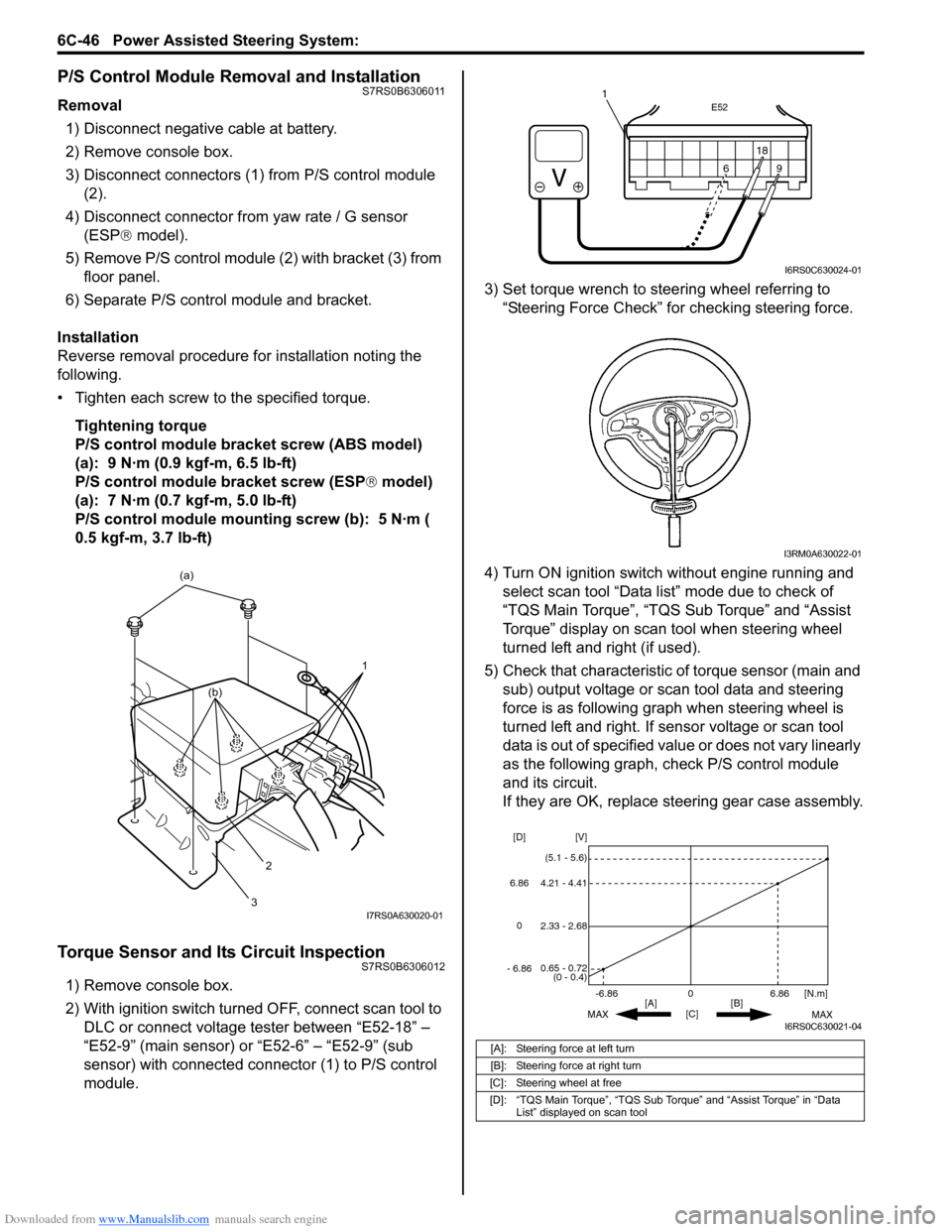
Removal1) Disconnect negative cable at battery.
2) Remove console box.
3) Disconnect connectors (1) from P/S control module (2).
4) Disconnect connector from yaw rate / G sensor
(ESP ® model).
5) Remove P/S control module (2) with bracket (3) from floor panel.
6) Separate P/S control module and bracket.
Installation
Reverse removal procedure for installation noting the
following.
• Tighten each screw to the specified torque. Tightening torque
P/S control module bracket screw (ABS model)
(a): 9 N·m (0.9 kgf-m, 6.5 lb-ft)
P/S control module bracket screw (ESP ® model)
(a): 7 N·m (0.7 kgf-m, 5.0 lb-ft)
P/S control module mounting screw (b): 5 N·m (
0.5 kgf-m, 3.7 lb-ft)
Torque Sensor and Its Circuit InspectionS7RS0B6306012
1) Remove console box.
2) With ignition switch turned OFF, connect scan tool to DLC or connect voltage tester between “E52-18” –
“E52-9” (main sensor) or “E52-6” – “E52-9” (sub
sensor) with connected connector (1) to P/S control
module. 3) Set torque wrench to stee
ring wheel referring to
“Steering Force Check” for checking steering force.
4) Turn ON ignition switch without engine running and select scan tool “Data list” mode due to check of
“TQS Main Torque”, “TQS Sub Torque” and “Assist
Torque” display on scan tool when steering wheel
turned left and right (if used).
5) Check that characteristic of torque sensor (main and sub) output voltage or scan tool data and steering
force is as following graph when steering wheel is
turned left and right. If sensor voltage or scan tool
data is out of specified value or does not vary linearly
as the following graph, check P/S control module
and its circuit.
If they are OK, replace steering gear case assembly.
1
(a)
2
3
(b)
I7RS0A630020-01
[A]: Steering force at left turn
[B]: Steering force at right turn
[C]: Steering wheel at free
[D]: “TQS Main Torque”, “TQS Sub Torque” and “Assist Torque” in “Data List” displayed on scan tool
E52
18
9
6
9
6 18
1
I6RS0C630024-01
I3RM0A630022-01
0
[C] [N.m]
MAX MAX
[B]
[A]
2.33 - 2.68 [V]
[D]
0.65 - 0.72
(0 - 0.4)
4.21 - 4.41
(5.1 - 5.6)
6.86
-6.86
0
6.86
- 6.86
I6RS0C630021-04
Page 929 of 1496
Downloaded from www.Manualslib.com manuals search engine Power Assisted Steering System: 6C-47
P/S Motor and Its Circuit InspectionS7RS0B6306013
1) Remove console box.
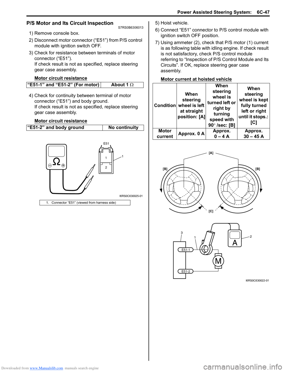
2) Disconnect motor connector (“E51”) from P/S control module with ignition switch OFF.
3) Check for resistance between terminals of motor connector (“E51”).
If check result is not as specified, replace steering
gear case assembly.
Motor circuit resistance
4) Check for continuity between terminal of motor connector (“E51”) and body ground.
If check result is not as specified, replace steering
gear case assembly.
Motor circuit resistance
5) Hoist vehicle.
6) Connect “E51” connector to P/S control module with ignition switch OFF position.
7) Using ammeter (2), check that P/S motor (1) current is as following table with id ling engine. If check result
is not satisfactory, check P/S control module
referring to “Inspection of P/S Control Module and Its
Circuits”. If OK, replace steering gear case
assembly.
Motor current at hoisted vehicle
“E51-1” and “E51-2” (For motor) About 1 Ω
“E51-2” and body ground No continuity
1. Connector “E51” (viewed from harness side)
E51
11 2
I6RS0C630025-01
Condition When
steering
wheel is left at straight
position: [A] When
steering
wheel is
turned left or right by turning
speed with
90° /sec: [B] When
steering
wheel is kept fully turned left or right
until it stops.: [C]
Motor
current Approx. 0 A Approx.
0 – 4 A Approx.
30 – 45 A
1
32
E51-1
E51-2
[C] [A]
[B] [B]
I6RS0C630022-01
Page 930 of 1496
Downloaded from www.Manualslib.com manuals search engine 6C-48 Power Assisted Steering System:
Specifications
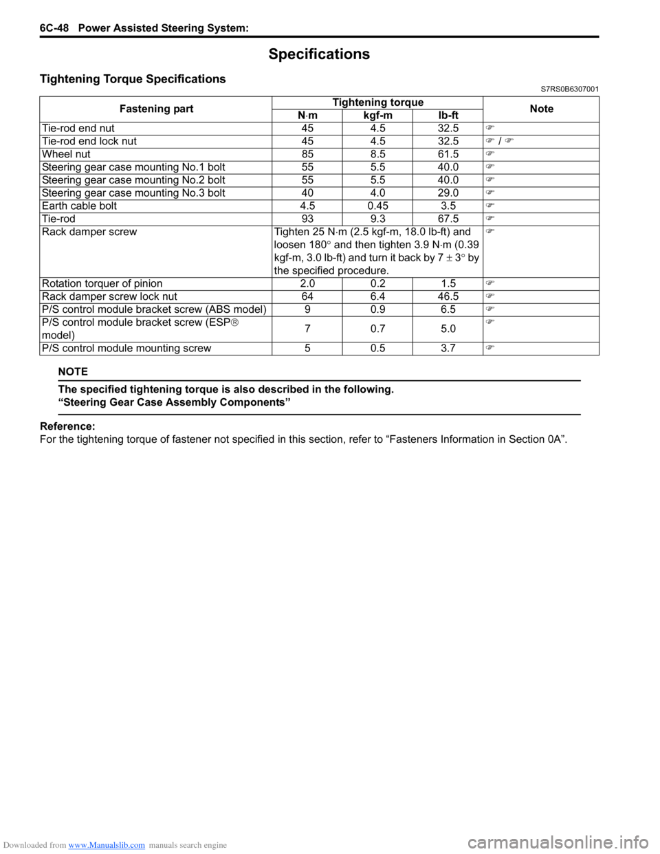
Tightening Torque SpecificationsS7RS0B6307001
NOTE
The specified tightening torque is also described in the following.
“Steering Gear Case Assembly Components”
Reference:
For the tightening torque of fastener not specified in this section, refer to “Fasteners Information in Section 0A”.
Fastening part
Tightening torque
Note
N ⋅mkgf-mlb-ft
Tie-rod end nut 454.5 32.5 �)
Tie-rod end lock nut 454.5 32.5 �) / �)
Wheel nut 858.5 61.5 �)
Steering gear case mounting No.1 bolt 555.5 40.0 �)
Steering gear case mounting No.2 bolt 555.5 40.0 �)
Steering gear case mounting No.3 bolt 404.0 29.0 �)
Earth cable bolt 4.5 0.45 3.5�)
Tie-rod 939.3 67.5 �)
Rack damper screw Tighten 25 N⋅m (2.5 kgf-m, 18.0 lb-ft) and
loosen 180 ° and then tighten 3.9 N ⋅m (0.39
kgf-m, 3.0 lb-ft) and turn it back by 7 ± 3° by
the specified procedure. �)
Rotation torquer of pinion 2.00.2 1.5 �)
Rack damper screw lock nut 646.4 46.5 �)
P/S control module bracket screw (ABS model) 9 0.9 6.5�)
P/S control module bracket screw (ESP ®
model) 70
.7 5 .0 �)
P/S control module mounting screw 50.5 3.7 �)
Page 1039 of 1496
Downloaded from www.Manualslib.com manuals search engine Air Bag System: 8B-1
Restraint
Air Bag System
Precautions
Precautions on Service and Diagnosis of Air
Bag System
S7RS0B8200001
WARNING!
• If the air bag system and another vehicle system both need repair, SUZUKI
recommends that the air bag system be
repaired first, to help avoid unintended air
bag system activation.
• Do not modify the steering wheel, dashboard, both front seat or any other on
or around air bag system components.
Modifications can adversely affect air bag
system performance and lead to injury.
• Be sure to follow the procedures described in this section. Failure to follow
procedures could result in possible air bag
system activation, personal injury or
unneeded air bag system repairs.
• WARNING / CAUTION labels are attached on each
part of air bag system components (SDM, air bag
(inflator) modules and seat belt pretensioners). Be
sure to follow the instructions.
• Many of service procedures require disconnection of
“A/BAG” fuse and air bag (inflator) module(s) (driver,
passenger, side of both si des and curtain of both
sides) from initiator circuit to avoid an accidental
deployment.
• Do not apply power to the air bag system unless all components are connected or a diagnostic flow
requests it, as this will set a DTC.
• The “Air Bag Diagnostic S ystem Check” must be the
starting point of any air bag diagnostics. The “Air Bag
Diagnostic System Check” will verify proper “AIR
BAG” warning right operatio n and will lead you to the
correct flow to diagnose any air bag malfunctions.
Bypassing these procedures may result in extended
diagnostic time, incorrect diagnosis, and incorrect
parts replacements. • Never use air bag component parts from another
vehicle.
• If the vehicle will be exposed to temperatures over 93
° C (200 °F) (for example, during a paint baking
process), remove the air bag system components
beforehand to avoid component damage or
unintended system activation.
• When handling the air bag (inflator) modules (driver, passenger, side of both si des and curtain of both
sides), seat belt pretensio ners (driver and passenger),
SDM, forward-sensor or side-sensor, be careful not to
drop it or apply an impact to it. If an excessive impact
was applied (e.g., SDM, forward-sensor and side-
sensor are dropped, air bag (inflator) module is
dropped from a height of 90 cm (3 ft) or more, seat
belt pretensioner (retractor assembly) is dropped from
a height of 30 cm (1 ft) or more), never attempt
disassembly or repair but replace it with a new one.
• When using electric welding, be sure to disconnect air bag (inflator) module connectors (driver, passenger,
side of both sides and curtain of both sides) and seat
belt pretensioner connectors (driver and passenger)
respectively.
• When applying paint around the air bag system related parts, use care so that the harness or
connector will not be expo sed to the paint mist.
• Never expose air bag system component parts directly to hot air (drying or baking the vehicle after
painting) or flames.
WARNING!
When performing service on or around air
bag system components or air bag wiring,
follow the procedures listed in “Disabling Air
Bag System” to temporarily disable the air
bag system.
Failure to follow procedures could result in
possible air bag system activation, personal
injury or unneeded air bag system repairs.
Page 1066 of 1496
Downloaded from www.Manualslib.com manuals search engine 8B-28 Air Bag System:
NOTE
Upon completion of inspection and repair work, perform the following items.
• Reconnect all air bag system components and ensure all components are properly mounted.
• Clear DTCs referring to “DTC Clearance”, if any.
• Repeat “Air Bag Diagnostic System Check” to confirm that the trouble has been corrected.
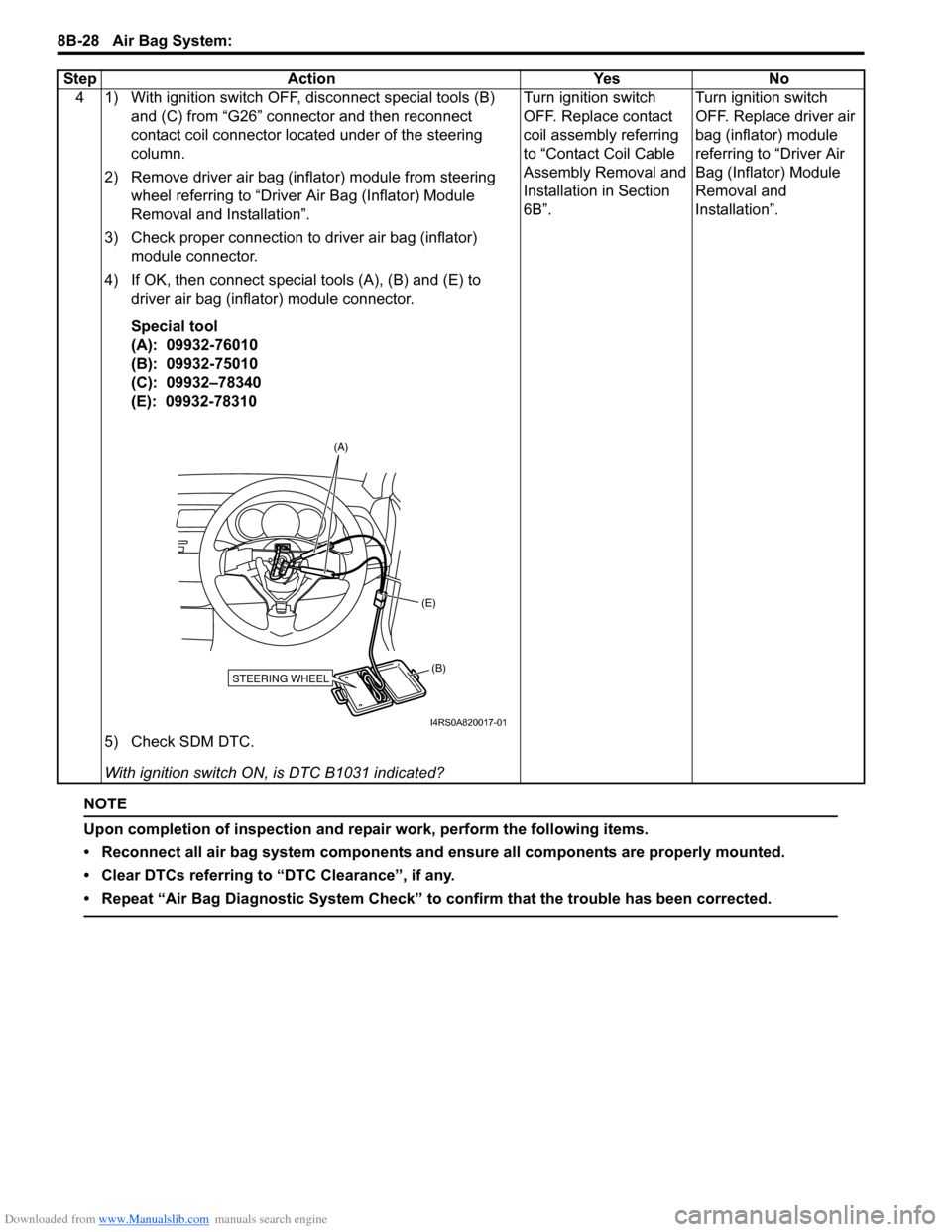
4 1) With ignition switch OFF, disconnect special tools (B) and (C) from “G26” connector and then reconnect
contact coil connector located under of the steering
column.
2) Remove driver air bag (inflator) module from steering wheel referring to “Driver Air Bag (Inflator) Module
Removal and Installation”.
3) Check proper connection to driver air bag (inflator) module connector.
4) If OK, then connect special tools (A), (B) and (E) to driver air bag (inflator) module connector.
Special tool
(A): 09932-76010
(B): 09932-75010
(C): 09932–78340
(E): 09932-78310
5) Check SDM DTC.
With ignition switch ON , is DTC B1031 indicated? Turn ignition switch
OFF. Replace contact
coil assembly referring
to “Contact Coil Cable
Assembly Removal and
Installation in Section
6B”.
Turn ignition switch
OFF. Replace driver air
bag (inflator) module
referring to “Driver Air
Bag (Inflator) Module
Removal and
Installation”.
Step Action Yes No
STEERING WHEEL(B)
(E)
(A)
I4RS0A820017-01
Page 1071 of 1496
Downloaded from www.Manualslib.com manuals search engine Air Bag System: 8B-33
NOTE
Upon completion of inspection and repair work, perform the following items.
• Reconnect all air bag system components and ensure all components are properly mounted.
• Clear DTCs referring to “DTC Clearance”, if any.
• Repeat “Air Bag Diagnostic System Check” to confirm that the trouble has been corrected.
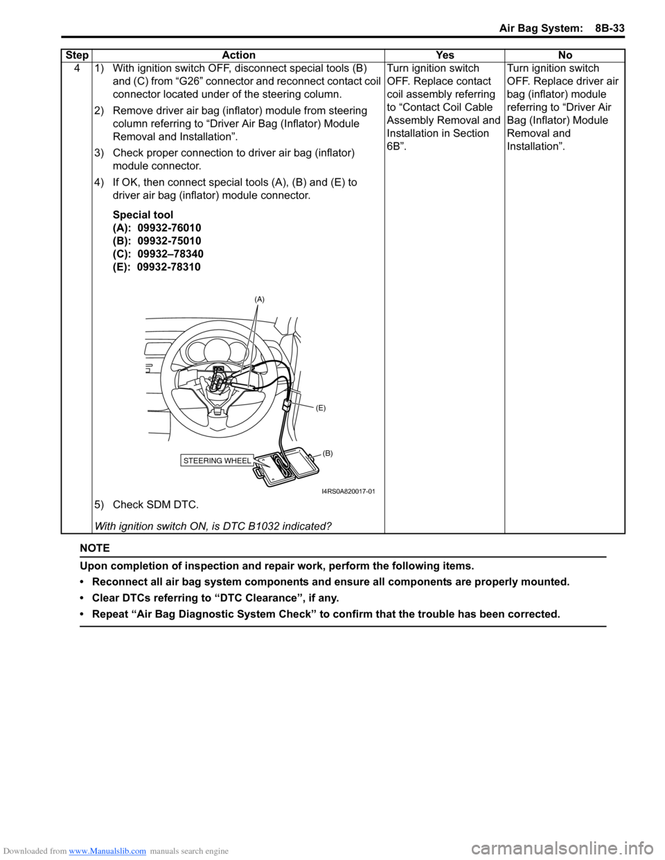
4 1) With ignition switch OFF, disconnect special tools (B) and (C) from “G26” connector and reconnect contact coil
connector located under of the steering column.
2) Remove driver air bag (inflator) module from steering column referring to “Driver Air Bag (Inflator) Module
Removal and Installation”.
3) Check proper connection to driver air bag (inflator) module connector.
4) If OK, then connect special tools (A), (B) and (E) to driver air bag (inflator) module connector.
Special tool
(A): 09932-76010
(B): 09932-75010
(C): 09932–78340
(E): 09932-78310
5) Check SDM DTC.
With ignition switch ON , is DTC B1032 indicated? Turn ignition switch
OFF. Replace contact
coil assembly referring
to “Contact Coil Cable
Assembly Removal and
Installation in Section
6B”.
Turn ignition switch
OFF. Replace driver air
bag (inflator) module
referring to “Driver Air
Bag (Inflator) Module
Removal and
Installation”.
Step Action Yes No
STEERING WHEEL(B)
(E)
(A)
I4RS0A820017-01
Page 1076 of 1496
Downloaded from www.Manualslib.com manuals search engine 8B-38 Air Bag System:
NOTE
Upon completion of inspection and repair work, perform the following items.
• Reconnect all air bag system components and ensure all components are properly mounted.
• Clear DTCs referring to “DTC Clearance”, if any.
• Repeat “Air Bag Diagnostic System Check” to confirm that the trouble has been corrected.
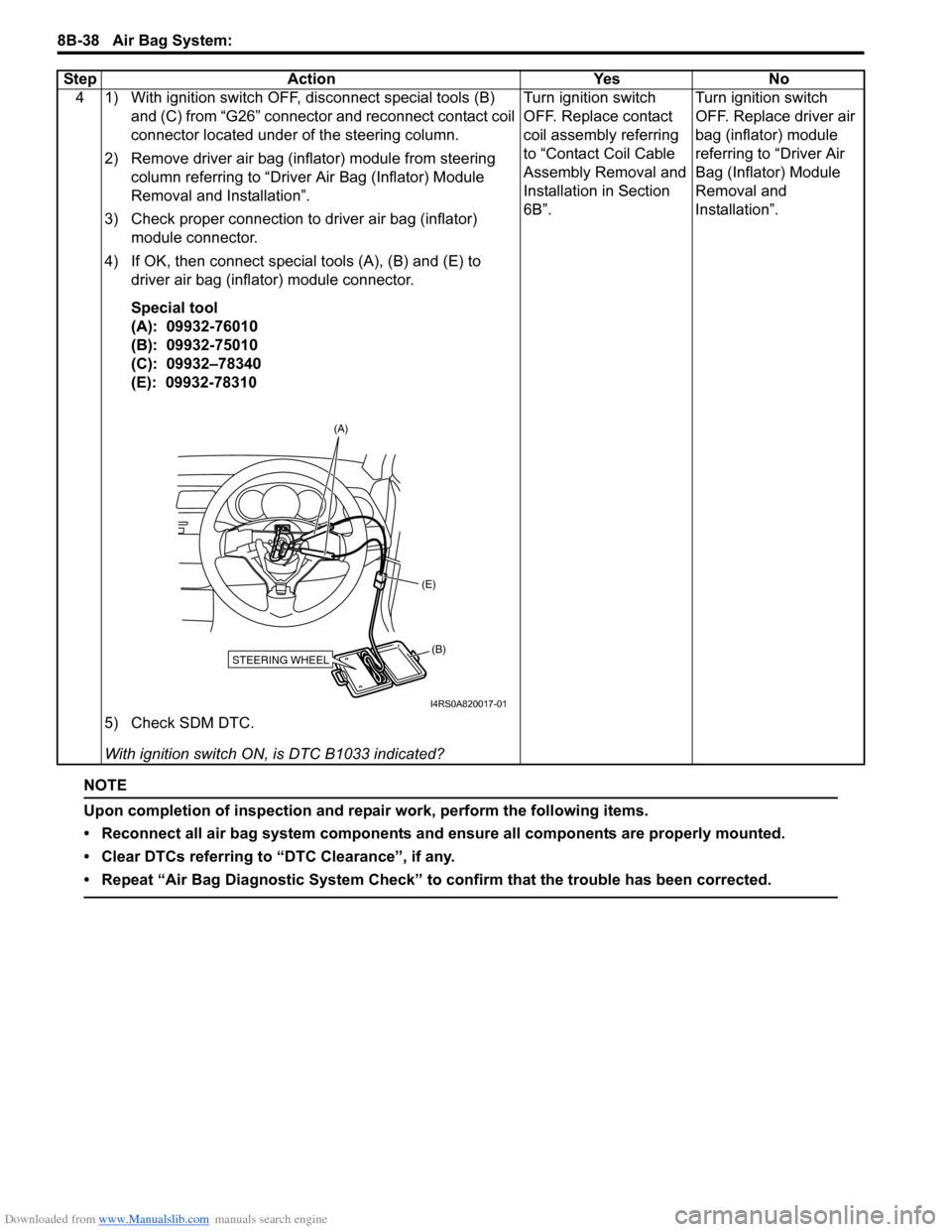
4 1) With ignition switch OFF, disconnect special tools (B) and (C) from “G26” connector and reconnect contact coil
connector located under of the steering column.
2) Remove driver air bag (inflator) module from steering column referring to “Driver Air Bag (Inflator) Module
Removal and Installation”.
3) Check proper connection to driver air bag (inflator) module connector.
4) If OK, then connect special tools (A), (B) and (E) to driver air bag (inflator) module connector.
Special tool
(A): 09932-76010
(B): 09932-75010
(C): 09932–78340
(E): 09932-78310
5) Check SDM DTC.
With ignition switch ON , is DTC B1033 indicated? Turn ignition switch
OFF. Replace contact
coil assembly referring
to “Contact Coil Cable
Assembly Removal and
Installation in Section
6B”.
Turn ignition switch
OFF. Replace driver air
bag (inflator) module
referring to “Driver Air
Bag (Inflator) Module
Removal and
Installation”.
Step Action Yes No
STEERING WHEEL(B)
(E)
(A)
I4RS0A820017-01
Page 1081 of 1496
Downloaded from www.Manualslib.com manuals search engine Air Bag System: 8B-43
NOTE
Upon completion of inspection and repair work, perform the following items.
• Reconnect all air bag system components and ensure all components are properly mounted.
• Clear DTCs referring to “DTC Clearance”, if any.
• Repeat “Air Bag Diagnostic System Check” to confirm that the trouble has been corrected.
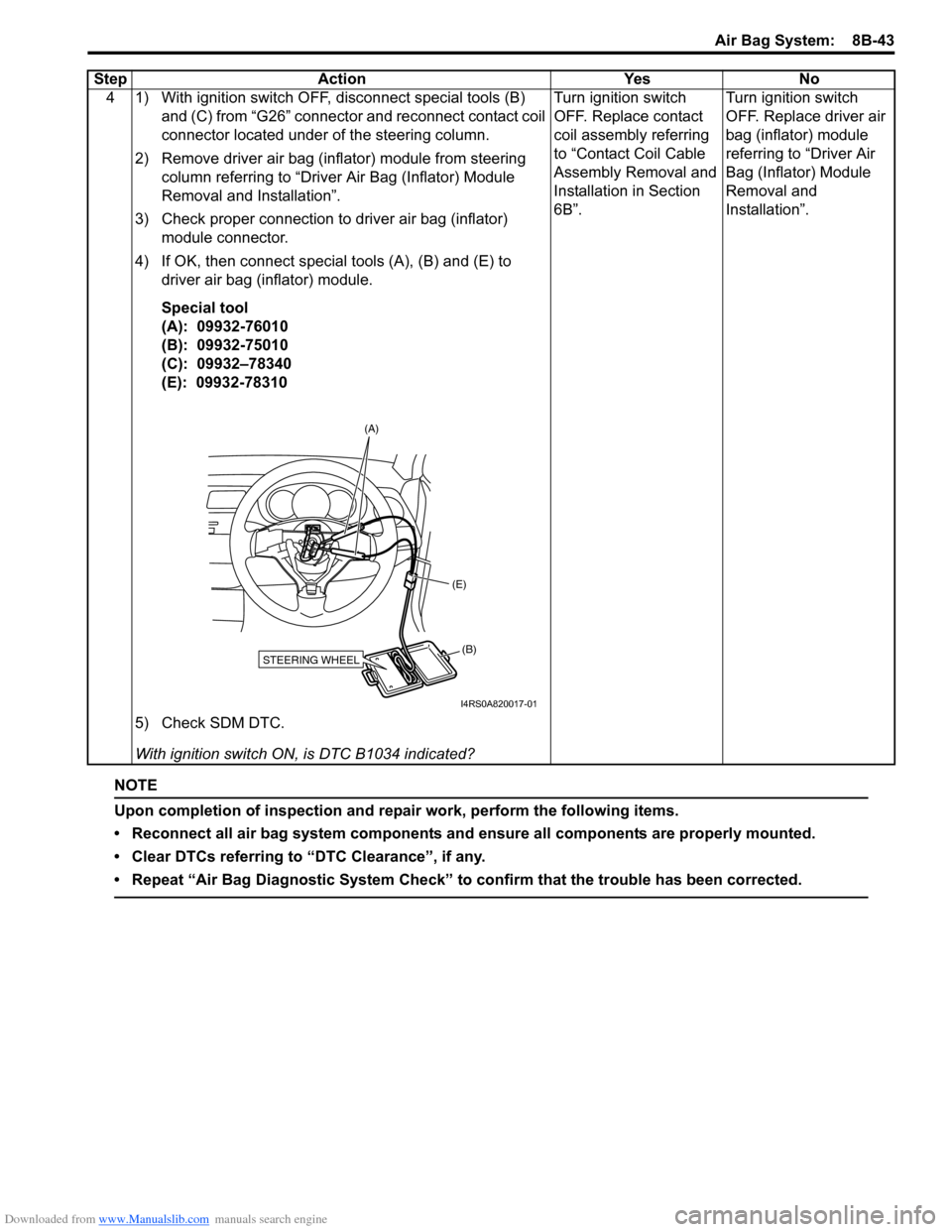
4 1) With ignition switch OFF, disconnect special tools (B) and (C) from “G26” connector and reconnect contact coil
connector located under of the steering column.
2) Remove driver air bag (inflator) module from steering column referring to “Driver Air Bag (Inflator) Module
Removal and Installation”.
3) Check proper connection to driver air bag (inflator) module connector.
4) If OK, then connect special tools (A), (B) and (E) to driver air bag (inflator) module.
Special tool
(A): 09932-76010
(B): 09932-75010
(C): 09932–78340
(E): 09932-78310
5) Check SDM DTC.
With ignition switch ON , is DTC B1034 indicated? Turn ignition switch
OFF. Replace contact
coil assembly referring
to “Contact Coil Cable
Assembly Removal and
Installation in Section
6B”.
Turn ignition switch
OFF. Replace driver air
bag (inflator) module
referring to “Driver Air
Bag (Inflator) Module
Removal and
Installation”.
Step Action Yes No
STEERING WHEEL(B)
(E)
(A)
I4RS0A820017-01
Page 1083 of 1496

Downloaded from www.Manualslib.com manuals search engine Air Bag System: 8B-45
DTC TroubleshootingStep Action YesNo
1 1) With ignition switch OFF, disconnect passenger air bag (inflator) module connector.
2) Check proper connection to passenger air bag (inflator) module at terminals in “G10” connector.
3) If OK, then connect special tools (A), (B) and (D) to “G10” connector.
Special tool
(A): 09932–76010
(B): 09932–75010
(D): 09932–78310
4) Check SDM DTC.
With ignition switch ON , is DTC B1041 indicated? Go to Step 2.
Turn ignition switch
OFF. Replace
passenger air bag
(inflator) module
referring to “Passenger
Air Bag (Inflator) Module
Removal and
Installation”.
STEERING WHEEL(B)
(D)
(A)
"G10"
I4RS0A820021-01
Page 1084 of 1496
Downloaded from www.Manualslib.com manuals search engine 8B-46 Air Bag System:
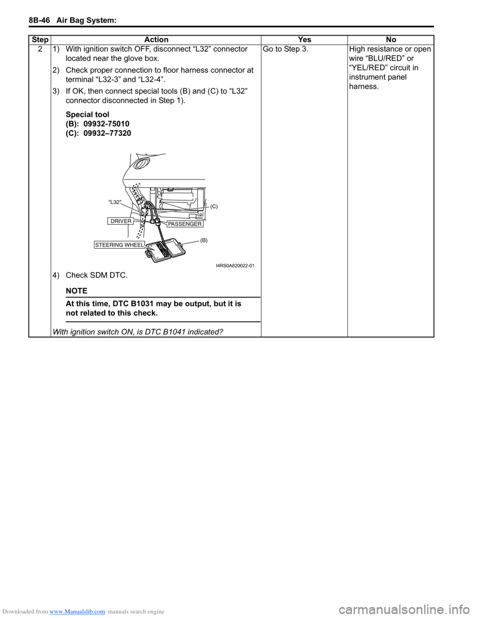
2 1) With ignition switch OFF, disconnect “L32” connector located near the glove box.
2) Check proper connection to floor harness connector at terminal “L32-3” and “L32-4”.
3) If OK, then connect special tools (B) and (C) to “L32” connector disconnected in Step 1).
Special tool
(B): 09932-75010
(C): 09932–77320
4) Check SDM DTC.
NOTE
At this time, DTC B1031 ma y be output, but it is
not related to this check.
With ignition switch ON , is DTC B1041 indicated? Go to Step 3. High resistance or open
wire “BLU/RED” or
“YEL/RED” circuit in
instrument panel
harness.
Step Action Yes No
(B) (C)
"L32"STEERING WHEEL
DRIVERPASSENGER
I4RS0A820022-01