Head removal SUZUKI SWIFT 2005 2.G Service Owner's Manual
[x] Cancel search | Manufacturer: SUZUKI, Model Year: 2005, Model line: SWIFT, Model: SUZUKI SWIFT 2005 2.GPages: 1496, PDF Size: 34.44 MB
Page 315 of 1496
Downloaded from www.Manualslib.com manuals search engine Engine Mechanical: 1D-30
Installation1) Install tappets and shims to cylinder head. Apply engine oil around tappet and then install it to
cylinder head.
NOTE
When installing shim, make sure to direct
shim No. side toward tappet.
2) Install camshaft bearing (1) to cylinder head.
CAUTION!
Do not apply engine oil to camshaft bearing
back.
Only a upper half bearing of intake camshaft
bearing No.1 has some holes. Other
bearings.
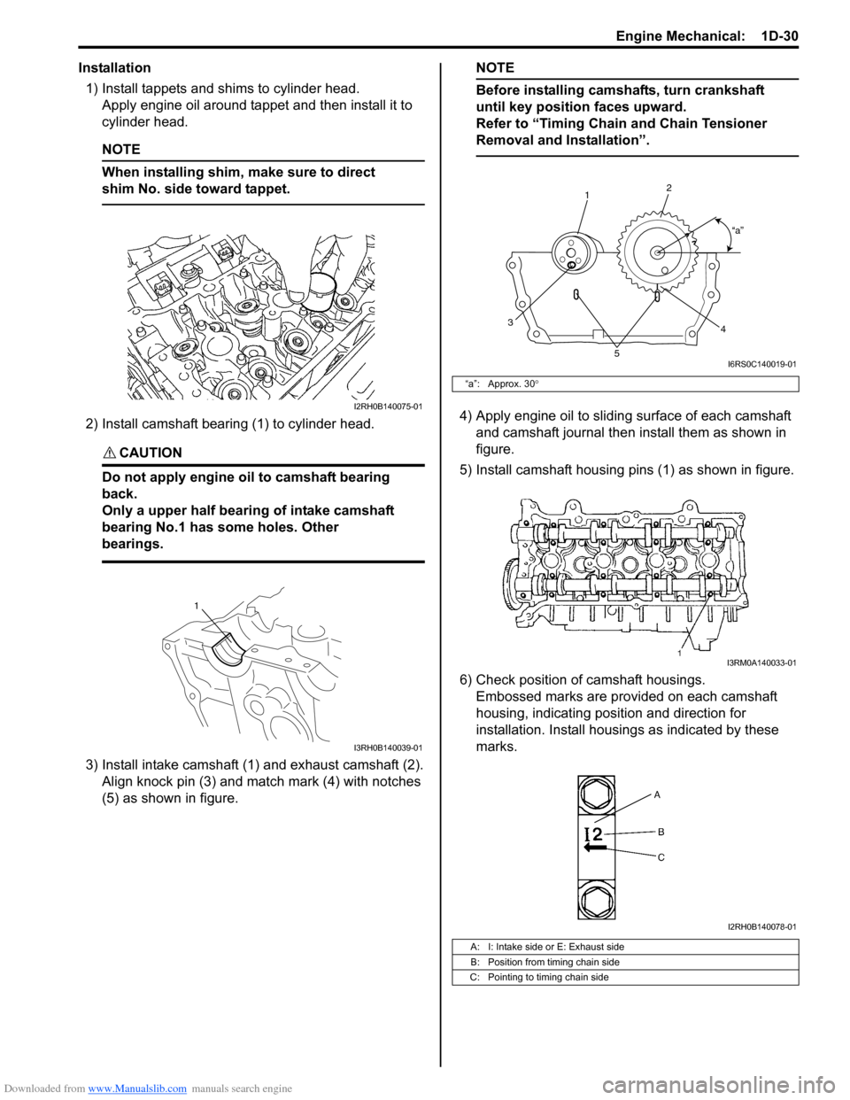
3) Install intake camshaft (1) and exhaust camshaft (2). Align knock pin (3) and match mark (4) with notches
(5) as shown in figure.
NOTE
Before installing camshafts, turn crankshaft
until key position faces upward.
Refer to “Timing Chain and Chain Tensioner
Removal and Installation”.
4) Apply engine oil to sliding surface of each camshaft and camshaft journal then install them as shown in
figure.
5) Install camshaft housing pins (1) as shown in figure.
6) Check position of camshaft housings. Embossed marks are provided on each camshaft
housing, indicating position and direction for
installation. Install housings as indicated by these
marks.I2RH0B140075-01
1
I3RH0B140039-01
“a”: Approx. 30 °
A: I: Intake side or E: Exhaust side
B: Position from timing chain side
C: Pointing to timing chain side
1 2
3 4
5
“a”
I6RS0C140019-01
I3RM0A140033-01
I2RH0B140078-01
Page 320 of 1496
Downloaded from www.Manualslib.com manuals search engine 1D-35 Engine Mechanical:
Valves and Cylinder Head Removal and
Installation
S7RS0B1406024
Removal1) Remove engine assembly from vehicle referring to “Engine Assembly Removal and Installation”.
2) Remove oil pan referring to “Oil Pan and Oil Pump
Strainer Removal and Installation in Section 1E”.
3) Remove cylinder head cover referring to “Cylinder Head Cover Removal and Installation”.
4) Remove timing chain cover referring to Steps 2) to 11) of “Removal” in “Tim ing Chain Cover Removal
and Installation”.
5) Remove timing chain referring to Steps 2) to 6) of “Removal” in “Timing Chain and Chain Tensioner
Removal and Installation”.
6) Remove intake and exhaust camshafts referring to Steps 3) to 8) of “Removal” in “Camshaft, Tappet and
Shim Removal and Installation”.
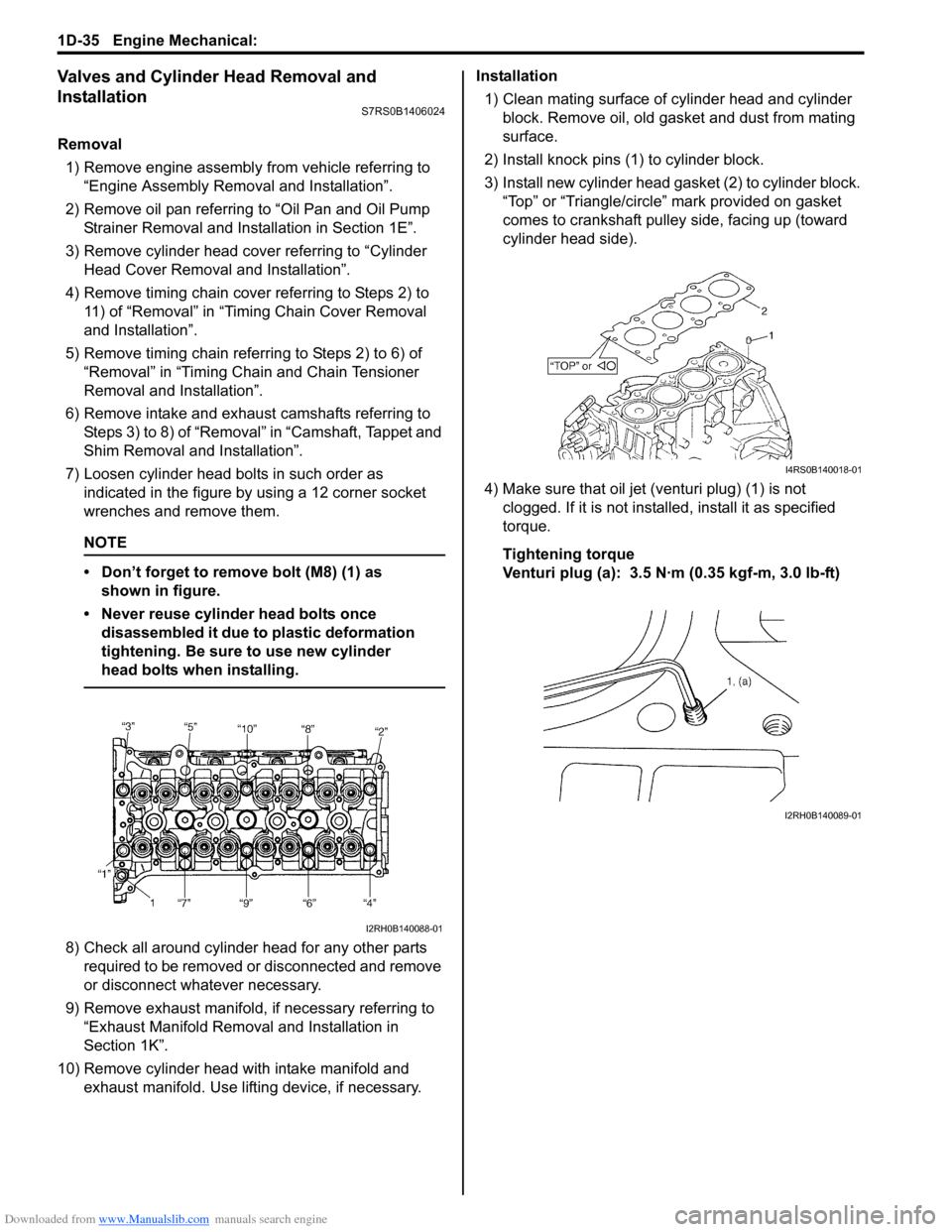
7) Loosen cylinder head bolts in such order as indicated in the figure by using a 12 corner socket
wrenches and remove them.
NOTE
• Don’t forget to remove bolt (M8) (1) as shown in figure.
• Never reuse cylinder head bolts once disassembled it due to plastic deformation
tightening. Be sure to use new cylinder
head bolts when installing.
8) Check all around cylinder head for any other parts required to be removed or disconnected and remove
or disconnect whatever necessary.
9) Remove exhaust manifold, if necessary referring to
“Exhaust Manifold Removal and Installation in
Section 1K”.
10) Remove cylinder head wi th intake manifold and
exhaust manifold. Use lifting device, if necessary. Installation
1) Clean mating surface of cylinder head and cylinder block. Remove oil, old gasket and dust from mating
surface.
2) Install knock pins (1) to cylinder block.
3) Install new cylinder head gasket (2) to cylinder block. “Top” or “Triangle/circle” mark provided on gasket
comes to crankshaft pulley side, facing up (toward
cylinder head side).
4) Make sure that oil jet (venturi plug) (1) is not clogged. If it is not install ed, install it as specified
torque.
Tightening torque
Venturi plug (a): 3.5 N·m (0.35 kgf-m, 3.0 lb-ft)
I2RH0B140088-01
I4RS0B140018-01
I2RH0B140089-01
Page 321 of 1496
Downloaded from www.Manualslib.com manuals search engine Engine Mechanical: 1D-36
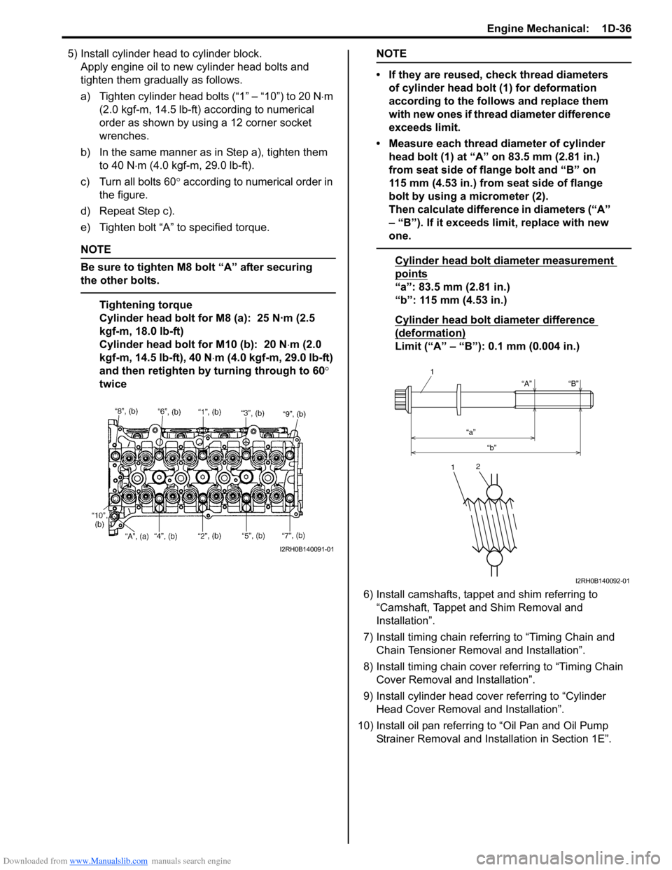
5) Install cylinder head to cylinder block.Apply engine oil to new cylinder head bolts and
tighten them gradually as follows.
a) Tighten cylinder head bolts (“1” – “10”) to 20 N ⋅m
(2.0 kgf-m, 14.5 lb-ft) according to numerical
order as shown by using a 12 corner socket
wrenches.
b) In the same manner as in Step a), tighten them to 40 N ⋅m (4.0 kgf-m, 29.0 lb-ft).
c) Turn all bolts 60 ° according to numerical order in
the figure.
d) Repeat Step c).
e) Tighten bolt “A” to specified torque.
NOTE
Be sure to tighten M8 bolt “A” after securing
the other bolts.
Tightening torque
Cylinder head bolt for M8 (a): 25 N·m (2.5
kgf-m, 18.0 lb-ft)
Cylinder head bolt for M10 (b): 20 N ⋅m (2.0
kgf-m, 14.5 lb-ft), 40 N ⋅m (4.0 kgf-m, 29.0 lb-ft)
and then retighten by turning through to 60 °
twice
NOTE
• If they are reused, check thread diameters of cylinder head bolt (1) for deformation
according to the follows and replace them
with new ones if thread diameter difference
exceeds limit.
• Measure each thread diameter of cylinder head bolt (1) at “A” on 83.5 mm (2.81 in.)
from seat side of flange bolt and “B” on
115 mm (4.53 in.) from seat side of flange
bolt by using a micrometer (2).
Then calculate difference in diameters (“A”
– “B”). If it exceeds limit, replace with new
one.
Cylinder head bolt diameter measurement
points
“a”: 83.5 mm (2.81 in.)
“b”: 115 mm (4.53 in.)
Cylinder head bolt diameter difference
(deformation)
Limit (“A” – “B”): 0.1 mm (0.004 in.)
6) Install camshafts, tappet and shim referring to “Camshaft, Tappet and Shim Removal and
Installation”.
7) Install timing chain referring to “Timing Chain and Chain Tensioner Remova l and Installation”.
8) Install timing chain cover referring to “Timing Chain Cover Removal and Installation”.
9) Install cylinder head cover referring to “Cylinder Head Cover Removal and Installation”.
10) Install oil pan referring to “Oil Pan and Oil Pump
Strainer Removal and Inst allation in Section 1E”.
I2RH0B140091-01
“A”
“a” “b” “B”
1
1
2
I2RH0B140092-01
Page 330 of 1496
Downloaded from www.Manualslib.com manuals search engine 1D-45 Engine Mechanical:
Pistons, Piston Rings, Connecting Rods and
Cylinders Removal and Installation
S7RS0B1406030
Removal1) Remove engine assembly from vehicle referring to “Engine Assembly Removal and Installation”.
2) Remove cylinder head referring to “Valves and Cylinder Head Removal and Installation”.
3) Mark cylinder number on all pistons, connecting rods
and connecting rod caps using silver pencil or quick
drying paint.
4) Remove rod bearing caps.
5) Decarbonize top of cylinder bore before removing piston from cylinder.
6) Push piston and connecting rod assembly out through the top of cylinder bore.
Installation 1) Apply engine oil to pistons, rings, cylinder walls, connecting rod bearings and crank pins.
NOTE
Do not apply oil between connecting rod and
bearing or between bearing cap and bearing.
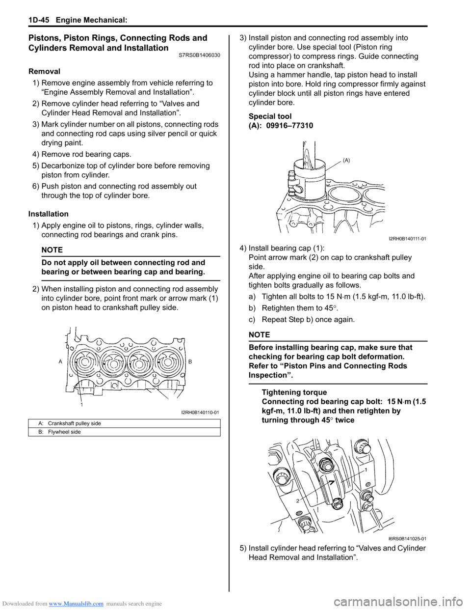
2) When installing piston and connecting rod assembly into cylinder bore, point front mark or arrow mark (1)
on piston head to crankshaft pulley side. 3) Install piston and connecting rod assembly into
cylinder bore. Use special tool (Piston ring
compressor) to compress rings. Guide connecting
rod into place on crankshaft.
Using a hammer handle, tap piston head to install
piston into bore. Hold ring compressor firmly against
cylinder block until all piston rings have entered
cylinder bore.
Special tool
(A): 09916–77310
4) Install bearing cap (1): Point arrow mark (2) on cap to crankshaft pulley
side.
After applying engine oil to bearing cap bolts and
tighten bolts gradually as follows.
a) Tighten all bolts to 15 N ⋅m (1.5 kgf-m, 11.0 lb-ft).
b) Retighten them to 45 °.
c) Repeat Step b) once again.
NOTE
Before installing bearing cap, make sure that
checking for bearing cap bolt deformation.
Refer to “Piston Pins and Connecting Rods
Inspection”.
Tightening torque
Connecting rod bearing cap bolt: 15 N ⋅m (1.5
kgf-m, 11.0 lb-ft) and then retighten by
turning through 45 ° twice
5) Install cylinder head referring to “Valves and Cylinder Head Removal and Installation”.
A: Crankshaft pulley side
B: Flywheel side
I2RH0B140110-01
I2RH0B140111-01
I6RS0B141025-01
Page 342 of 1496
Downloaded from www.Manualslib.com manuals search engine 1D-57 Engine Mechanical:
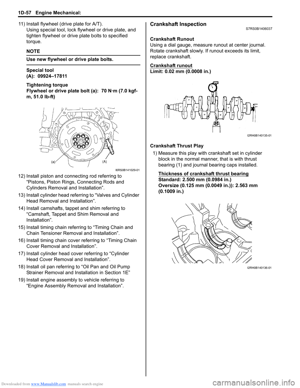
11) Install flywheel (drive plate for A/T).Using special tool, lock flyw heel or drive plate, and
tighten flywheel or drive plate bolts to specified
torque.
NOTE
Use new flywheel or drive plate bolts.
Special tool
(A): 09924–17811
Tightening torque
Flywheel or drive plate bolt (a): 70 N·m (7.0 kgf-
m, 51.0 lb-ft)
12) Install piston and connecting rod referring to “Pistons, Piston Rings, Connecting Rods and
Cylinders Removal and Installation”.
13) Install cylinder head referring to “Valves and Cylinder Head Removal and Installation”.
14) Install camshafts, tappet and shim referring to “Camshaft, Tappet and Shim Removal and
Installation”.
15) Install timing chain referring to “Timing Chain and Chain Tensioner Removal and Installation”.
16) Install timing chain cover referring to “Timing Chain Cover Removal and Installation”.
17) Install cylinder head cover referring to “Cylinder Head Cover Removal and Installation”.
18) Install oil pan referring to “Oil Pan and Oil Pump
Strainer Removal and Installation in Section 1E”
19) Install engine assembly to vehicle referring to “Engine Assembly Removal and Installation”.
Crankshaft InspectionS7RS0B1406037
Crankshaft Runout
Using a dial gauge, measure runout at center journal.
Rotate crankshaft slowly. If runout exceeds its limit,
replace crankshaft.
Crankshaft runout
Limit: 0.02 mm (0.0008 in.)
Crankshaft Thrust Play
1) Measure this play with crankshaft set in cylinder block in the normal manner, that is with thrust
bearing (1) and journal bearing caps installed.
Thickness of crankshaft thrust bearing
Standard: 2.500 mm (0.0984 in.)
Oversize (0.125 mm (0.0049 in.)): 2.563 mm
(0.1009 in.)
I6RS0B141029-01
I2RH0B140135-01
I2RH0B140136-01
Page 384 of 1496
Downloaded from www.Manualslib.com manuals search engine 1G-9 Fuel System:
Installation
Reverse removal procedure for installation noting the
following.
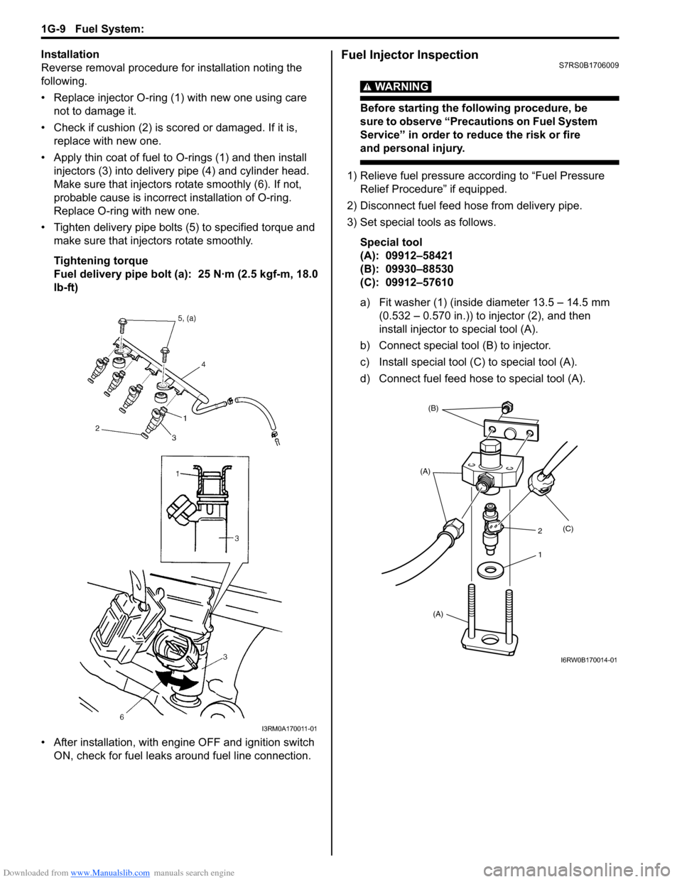
• Replace injector O-ring (1) with new one using care not to damage it.
• Check if cushion (2) is scor ed or damaged. If it is,
replace with new one.
• Apply thin coat of fuel to O-rings (1) and then install injectors (3) into delivery pipe (4) and cylinder head.
Make sure that injectors rota te smoothly (6). If not,
probable cause is incorrect installation of O-ring.
Replace O-ring with new one.
• Tighten delivery pipe bolts (5) to specified torque and make sure that inject ors rotate smoothly.
Tightening torque
Fuel delivery pipe bolt (a): 25 N·m (2.5 kgf-m, 18.0
lb-ft)
• After installation, with engine OFF and ignition switch ON, check for fuel leaks around fuel line connection.Fuel Injector InspectionS7RS0B1706009
WARNING!
Before starting the following procedure, be
sure to observe “Precautions on Fuel System
Service” in order to reduce the risk or fire
and personal injury.
1) Relieve fuel pressure according to “Fuel Pressure Relief Procedure” if equipped.
2) Disconnect fuel feed hose from delivery pipe.
3) Set special tools as follows.
Special tool
(A): 09912–58421
(B): 09930–88530
(C): 09912–57610
a) Fit washer (1) (inside diameter 13.5 – 14.5 mm (0.532 – 0.570 in.)) to injector (2), and then
install injector to special tool (A).
b) Connect special tool (B) to injector.
c) Install special tool (C) to special tool (A).
d) Connect fuel feed hose to special tool (A).
I3RM0A170011-01
(B)
(A)
(A) (C)
2
1
I6RW0B170014-01
Page 386 of 1496

Downloaded from www.Manualslib.com manuals search engine 1G-11 Fuel System:
Fuel Tank Inlet Valve Removal and InstallationS7RS0B1706011
WARNING!
Before starting the following procedure, be
sure to observe “Precautions on Fuel System
Service” in order to reduce the risk or fire
and personal injury.
Removal1) Remove fuel filler cap.
2) Insert hose of a hand oper ated pump into fuel filler
hose (1) and drain fuel in space “A” as shown in
figure.
CAUTION!
Do not force pump hose into fuel tank, or
pump hose may damage to fuel tank inlet
valve (2).
3) Hoist vehicle, and remove clamp (2) and fuel filler
hose (1) from fuel tank. 4) Remove fuel tank inlet valve (1) using flat head rod
(2) or the like.
CAUTION!
Be careful not to damage fuel tank inlet valve
(1) with flat head rod (2) or the like.
Installation
1) Install fuel tank inlet valve (1) to fuel tank.
2) Install fuel filler hose (1) to fuel tank and secure it
with clamp (2).
For proper installation, refer to “Fuel Hose
Disconnecting and Reconnecting”.
3) Lower vehicle and install fuel filler cap.
IYSQ01170010-01
1
2
I4RS0A170007-01
I6RS0C170007-01
I2RH0B170018-01
1
2
I4RS0A170007-01
Page 398 of 1496
Downloaded from www.Manualslib.com manuals search engine 1H-6 Ignition System:
Ignition Spark TestS7RS0B1804004
1) Remove air cleaner assembly with air intake pipe.
2) Disconnect all injector couplers from injectors.
WARNING!
Without disconnection of injector couplers,
combustible gas may come out from spark
plug holes during this test and may get
ignited in engine room.
3) Remove spark plug and check it for condition and
type referring to “Spark Plug Inspection”.
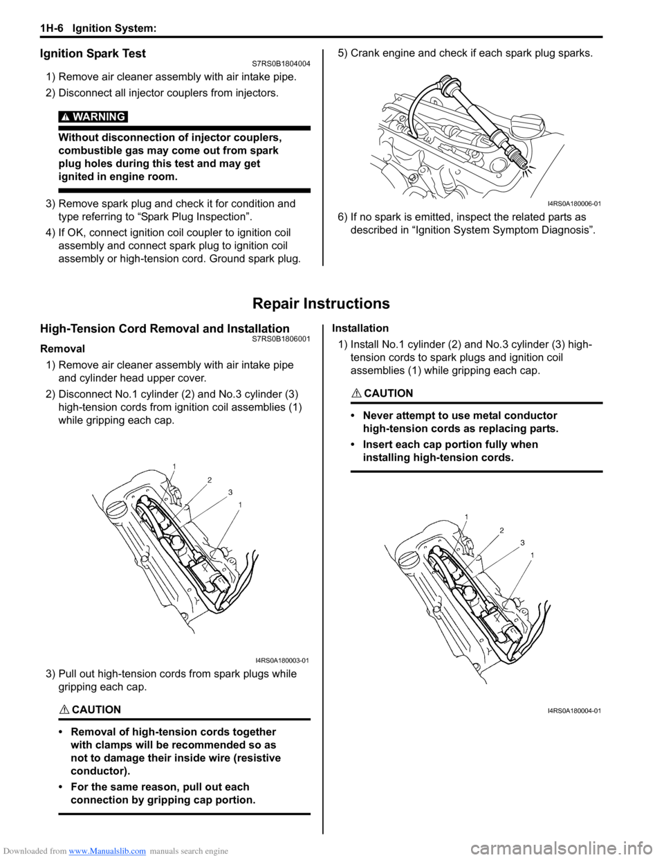
4) If OK, connect ignition coil coupler to ignition coil assembly and connect spark plug to ignition coil
assembly or high-tension cord. Ground spark plug. 5) Crank engine and check if each spark plug sparks.
6) If no spark is emitted, inspect the related parts as
described in “Ignition System Symptom Diagnosis”.
Repair Instructions
High-Tension Cord Removal and InstallationS7RS0B1806001
Removal
1) Remove air cleaner assembly with air intake pipe and cylinder head upper cover.
2) Disconnect No.1 cylinder (2) and No.3 cylinder (3)
high-tension cords from ignition coil assemblies (1)
while gripping each cap.
3) Pull out high-tension cords from spark plugs while gripping each cap.
CAUTION!
• Removal of high-tension cords together with clamps will be recommended so as
not to damage their inside wire (resistive
conductor).
• For the same reason, pull out each connection by gripping cap portion.
Installation
1) Install No.1 cylinder (2) and No.3 cylinder (3) high-
tension cords to spark plugs and ignition coil
assemblies (1) while gripping each cap.
CAUTION!
• Never attempt to use metal conductor high-tension cords as replacing parts.
• Insert each cap portion fully when installing high-tension cords.
I4RS0A180006-01
I4RS0A180003-01
I4RS0A180004-01
Page 399 of 1496
Downloaded from www.Manualslib.com manuals search engine Ignition System: 1H-7
High-Tension Cord InspectionS7RS0B1806002
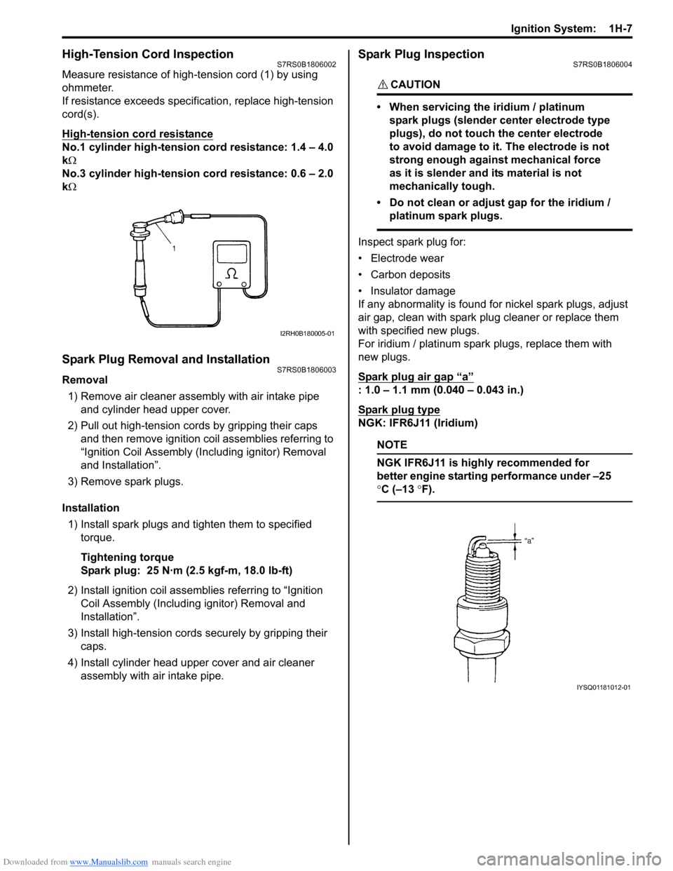
Measure resistance of high-tension cord (1) by using
ohmmeter.
If resistance exceeds specification, replace high-tension
cord(s).
High-tension cord resistance
No.1 cylinder high-tension cord resistance: 1.4 – 4.0
k Ω
No.3 cylinder high-tension cord resistance: 0.6 – 2.0
k Ω
Spark Plug Removal and InstallationS7RS0B1806003
Removal
1) Remove air cleaner assembly with air intake pipe and cylinder head upper cover.
2) Pull out high-tension cords by gripping their caps and then remove ignition coil assemblies referring to
“Ignition Coil Assembly (Inc luding ignitor) Removal
and Installation”.
3) Remove spark plugs.
Installation 1) Install spark plugs and tighten them to specified torque.
Tightening torque
Spark plug: 25 N·m (2.5 kgf-m, 18.0 lb-ft)
2) Install ignition coil assemblies referring to “Ignition Coil Assembly (Including ignitor) Removal and
Installation”.
3) Install high-tension cords securely by gripping their caps.
4) Install cylinder head upper cover and air cleaner assembly with air intake pipe.
Spark Plug InspectionS7RS0B1806004
CAUTION!
• When servicing the iridium / platinum
spark plugs (slender center electrode type
plugs), do not touch the center electrode
to avoid damage to it. The electrode is not
strong enough against mechanical force
as it is slender and its material is not
mechanically tough.
• Do not clean or adjust gap for the iridium / platinum spark plugs.
Inspect spark plug for:
• Electrode wear
• Carbon deposits
• Insulator damage
If any abnormality is found for nickel spark plugs, adjust
air gap, clean with spark plug cleaner or replace them
with specified new plugs.
For iridium / platinum spark plugs, replace them with
new plugs.
Spark plug air gap
“a”
: 1.0 – 1.1 mm (0.040 – 0.043 in.)
Spark plug type
NGK: IFR6J11 (Iridium)
NOTE
NGK IFR6J11 is highly recommended for
better engine starting performance under –25
°C (–13 °F).
I2RH0B180005-01
IYSQ01181012-01
Page 400 of 1496

Downloaded from www.Manualslib.com manuals search engine 1H-8 Ignition System:
Ignition Coil Assembly (Including ignitor)
Removal and Installation
S7RS0B1806005
Removal1) Disconnect negative (–) cable at battery.
2) Remove air cleaner assembly with air intake pipe and cylinder head upper cover.
3) Disconnect ignition coil coupler.
4) Disconnect high-tension cord (3) from ignition coil assembly (2).
5) Remove ignition coil bolts (1) and then pull out ignition coil assembly.
Installation 1) Install ignition coil assembly (2).
2) Tighten ignition coil bolts (1) to specified torque, and then connect igni tion coil coupler.
Tightening torque
Ignition coil bolt (a): 10 N·m (1.0 kgf-m, 7.5 lb-ft)
3) Install high-tension cord (3) to ignition coil assembly while gripping its cap.
4) Install cylinder head upper cover and air cleaner assembly with air intake pipe.
5) Connect negative (–) cable to battery.
Ignition Coil Assembly (Including ignitor)
Inspection
S7RS0B1806006
Measure secondary coil for resistance.
If resistance is out of specification, replace ignition coil
assembly.
Secondary coil resistance
7.5 – 10.3 k Ω at 20 °C, 68 ° F
Ignition Timing InspectionS7RS0B1806007
NOTE
• Ignition timing is not adjustable. If ignition
timing is out of specification, check
system related parts.
• Before starting engine, place transmission gear shift lever in “Neutral” (shift selector
lever to “P” range for A/T model), and set
parking brake.
1) Connect scan tool to DLC (1) with ignition switch OFF.
Special tool
(A): SUZUKI scan tool
2) Start engine and warm it up to normal operating temperature.
3) Make sure that all of electrical loads except ignition are switched off.
4) Check to be sure that idle speed is within specification referring to “Idle Speed and IAC
Throttle Valve Opening Inspection in Section 1A”
5) Fix ignition timing by using “Fixed Spark” of “Misc Test” mode on scan tool.
I2RH0B180006-01
I3RM0A180004-01
I2RH0B180007-01
(A)
1
I4RS0B180003-01