Intake air temp sensor SUZUKI SWIFT 2005 2.G Service Owner's Manual
[x] Cancel search | Manufacturer: SUZUKI, Model Year: 2005, Model line: SWIFT, Model: SUZUKI SWIFT 2005 2.GPages: 1496, PDF Size: 34.44 MB
Page 149 of 1496
Downloaded from www.Manualslib.com manuals search engine Engine General Information and Diagnosis: 1A-99
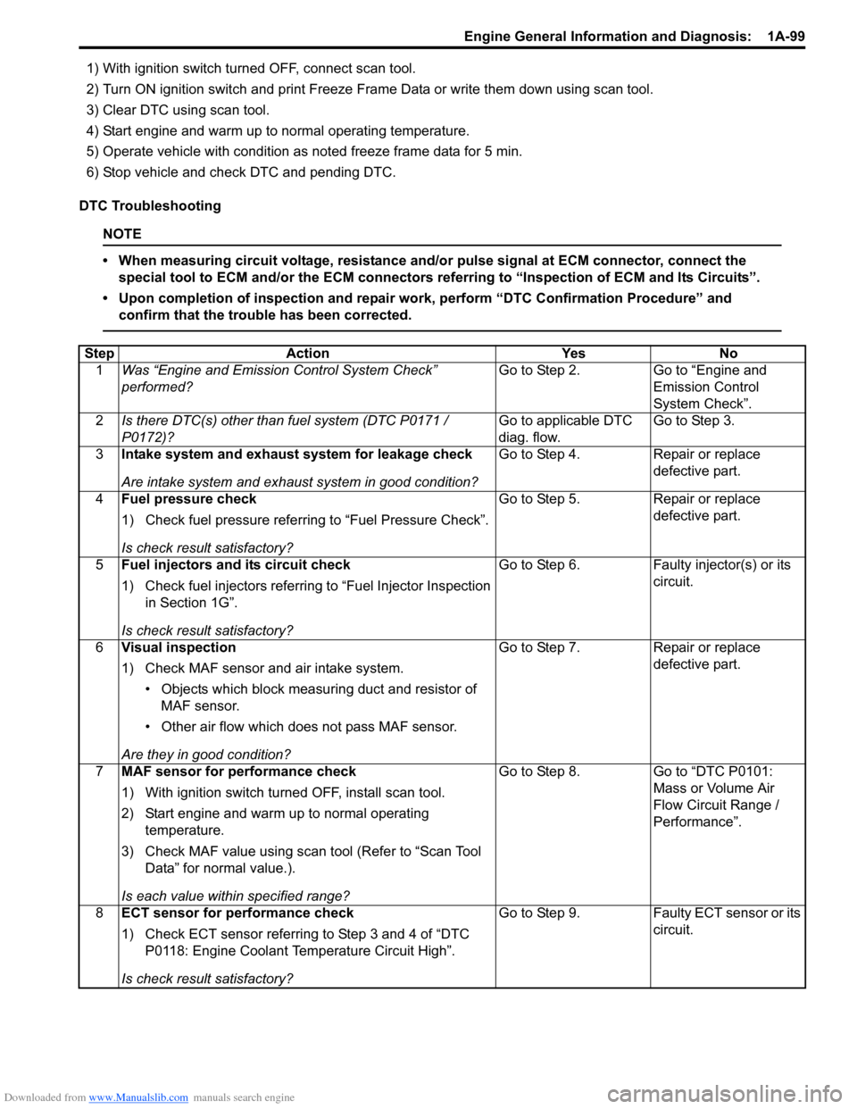
1) With ignition switch turned OFF, connect scan tool.
2) Turn ON ignition switch and print Freeze Frame Data or write them down using scan tool.
3) Clear DTC using scan tool.
4) Start engine and warm up to normal operating temperature.
5) Operate vehicle with condition as noted freeze frame data for 5 min.
6) Stop vehicle and check DTC and pending DTC.
DTC Troubleshooting
NOTE
• When measuring circuit voltage, resistance and/ or pulse signal at ECM connector, connect the
special tool to ECM and/or the ECM connectors re ferring to “Inspection of ECM and Its Circuits”.
• Upon completion of inspection and repair work, perform “DTC Confirmation Procedure” and confirm that the trouble has been corrected.
Step Action YesNo
1 Was “Engine and Emission Control System Check”
performed? Go to Step 2.
Go to “Engine and
Emission Control
System Check”.
2 Is there DTC(s) other than fuel system (DTC P0171 /
P0172)? Go to applicable DTC
diag. flow.Go to Step 3.
3 Intake system and exhaust system for leakage check
Are intake system and exhaust system in good condition? Go to Step 4.
Repair or replace
defective part.
4 Fuel pressure check
1) Check fuel pressure referring to “Fuel Pressure Check”.
Is check result satisfactory? Go to Step 5.
Repair or replace
defective part.
5 Fuel injectors and its circuit check
1) Check fuel injectors referring to “Fuel Injector Inspection
in Section 1G”.
Is check result satisfactory? Go to Step 6.
Faulty injector(s) or its
circuit.
6 Visual inspection
1) Check MAF sensor and air intake system.
• Objects which block measur ing duct and resistor of
MAF sensor.
• Other air flow which does not pass MAF sensor.
Are they in good condition? Go to Step 7.
Repair or replace
defective part.
7 MAF sensor for performance check
1) With ignition switch turn ed OFF, install scan tool.
2) Start engine and warm up to normal operating temperature.
3) Check MAF value using scan tool (Refer to “Scan Tool Data” for normal value.).
Is each value within specified range? Go to Step 8.
Go to “DTC P0101:
Mass or Volume Air
Flow Circuit Range /
Performance”.
8 ECT sensor for performance check
1) Check ECT sensor referring to Step 3 and 4 of “DTC
P0118: Engine Coolant Temperature Circuit High”.
Is check result satisfactory? Go to Step 9.
Faulty ECT sensor or its
circuit.
Page 155 of 1496
Downloaded from www.Manualslib.com manuals search engine Engine General Information and Diagnosis: 1A-105
DTC P0300 / P0301 / P0302 / P0303 / P0304: Random / Multiple Cylinder Misfire Detected / Cylinder 1
/ Cylinder 2 / Cylinder 3 / Cylinder 4 Misfire Detected
S7RS0B1104039
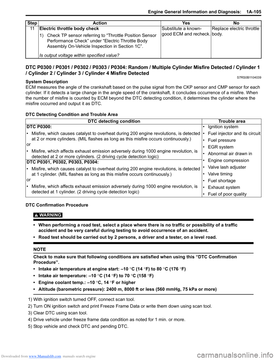
System Description
ECM measures the angle of the crankshaft based on the pulse signal from the CKP sensor and CMP sensor for each
cylinder. If it detects a large change in the angle speed of the crankshaft, it concludes occurrence of a misfire. When
the number of misfire is counted by ECM beyond the DTC de tecting condition, it determines the cylinder where the
misfire occurred and output it as DTC.
DTC Detecting Condition and Trouble Area
DTC Confirmation Procedure
WARNING!
• When performing a road test, select a place where there is no traffic or possibility of a traffic accident and be very careful during testing to avoid occurrence of an accident.
• Road test should be carried out by 2 persons, a driver and a tester, on a level road.
NOTE
Check to make sure that following conditions ar e satisfied when using this “DTC Confirmation
Procedure”.
• Intake air temperature at engine start: –10 °C (14 ° F) to 80 °C (176 °F)
• Intake air temperature: –10 °C (14 °F) to 70 °C (158 °F)
• Engine coolant temp.: –10 °C, 14 °F or higher
• Altitude (barometric pressure): 2400 m, 8000 ft or less (560 mmHg, 75 kPa or more)
1) With ignition switch turned OFF, connect scan tool.
2) Turn ON ignition switch and print Freeze Frame Data or write them down using scan tool.
3) Clear DTC using scan tool.
4) Drive vehicle under freeze frame data condition as noted for 1 min. or more.
5) Stop vehicle and check DTC and pending DTC. 11
Electric throttle body check
1) Check TP sensor referring to “Throttle Position Sensor
Performance Check” under “Electric Throttle Body
Assembly On-Vehicle Inspection in Section 1C”.
Is output voltage within specified value? Substitute a known-
good ECM and recheck.
Replace electric throttle
body.
Step Action Yes No
DTC detecting condition
Trouble area
DTC P0300:
• Misfire, which causes catalyst to overheat during 200 engine revolutions, is detected at 2 or more cylinders. (MIL flashes as lo ng as this misfire occurs continuously.)
or
• Misfire, which affects exhaust emission adv ersely during 1000 engine revolution, is
detected at 2 or more cylinders. (2 driving cycle detection logic) • Ignition system
• Fuel injector and its circuit
• Fuel pressure
• EGR system
• Abnormal air drawn in
• Engine compression
• Valve lash adjuster
• Valve timing
• Fuel shortage
• Exhaust system
• Fuel of poor quality
DTC P0301, P0302, P0303, P0304:
• Misfire, which causes catalyst to overheat during 200 engine revolutions, is detected
at 1 cylinder. (MIL flashes as long as this misfire occurs continuously.)
or
• Misfire, which affects exhaust emission adv ersely during 1000 engine revolution, is
detected at 1 cylinder. (2 driving cycle detection logic)
Page 167 of 1496
Downloaded from www.Manualslib.com manuals search engine Engine General Information and Diagnosis: 1A-117
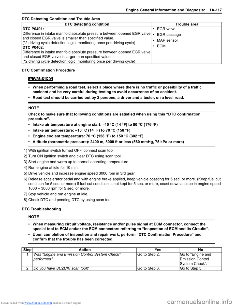
DTC Detecting Condition and Trouble Area
DTC Confirmation Procedure
WARNING!
• When performing a road test, select a place where there is no traffic or possibility of a traffic accident and be very careful during testing to avoid occurrence of an accident.
• Road test should be carried out by 2 persons, a driver and a tester, on a level road.
NOTE
Check to make sure that following conditions ar e satisfied when using this “DTC confirmation
procedure”.
• Intake air temperature at engine start: –10 °C (14 ° F) to 80 °C (176 °F)
• Intake air temperature: –10 °C (14 °F) to 70 °C (158 °F)
• Engine coolant temperature: 70 °C (158 °F) to 150 °C (302 °F)
• Altitude (barometric pressure): 2400 m, 8000 ft or less (560 mmHg, 75 kPa or more)
1) With ignition switch turned OFF, connect scan tool.
2) Turn ON ignition switch and clear DTC using scan tool.
3) Start engine and warm up to normal operating temperature.
4) Run engine at idle for 10 min.
5) Drive vehicle and increase engine speed 3000 rpm in 3rd gear.
6) Release accelerator pedal and with engine brake applied, keep vehicle coasting for 5 sec. or more. (Keep fuel cut condition for 5 sec. or more) If fuel cut condition is not ke pt for 5 sec. or more, coast down a slope in engine speed
1000 – 3000 rpm for 5 sec. or more.
7) Stop vehicle and run engine at idle.
8) Check DTC and pending DTC by using scan tool.
DTC Troubleshooting
NOTE
• When measuring circuit voltage, resistance and/ or pulse signal at ECM connector, connect the
special tool to ECM and/or the ECM connectors re ferring to “Inspection of ECM and Its Circuits”.
• Upon completion of inspection and repair work, perform “DTC Confirmation Procedure” and confirm that the trouble has been corrected.
DTC detecting condition Trouble area
DTC P0401:
Difference in intake manifold absolute pressure between opened EGR valve
and closed EGR valve is smaller than specified value.
(*2 driving cycle detection logic, monitoring once per driving cycle)
DTC P0402:
Difference in intake manifold absolute pressure between opened EGR valve
and closed EGR valve is la rger than specified value.
(*2 driving cycle detection logic, monitoring once per driving cycle) •EGR valve
• EGR passage
• MAP sensor
•ECM
Step
Action YesNo
1 Was “Engine and Emission Control System Check”
performed? Go to Step 2.
Go to “Engine and
Emission Control
System Check”.
2 Do you have SUZUKI scan tool? Go to Step 3.Go to Step 5.
Page 933 of 1496

Downloaded from www.Manualslib.com manuals search engine Table of Contents 7- i
7
Section 7
CONTENTS
HVAC
Precautions ................................................. 7-1
Precautions............................................................. 7-1
Precautions on HVAC ........................................... 7-1
Heater and Ventilation.... ......................... 7A-1
General Description ............................................. 7A-1
Heater and Ventilation Construction ................... 7A-1
Schematic and Routing Diagram ........................ 7A-2 Heater and Ventilation Wiring Circuit Diagram .... 7A-2
Diagnostic Information and Procedures ............ 7A-3 Heater and Ventilation Symptom Diagnosis........ 7A-3
Repair Instructions .............................................. 7A-4 HVAC Unit Components ..................................... 7A-4
HVAC Unit Removal and Installation .................. 7A-4
Blower Motor Removal and Installation............... 7A-4
Blower Motor Inspection ..................................... 7A-4
Blower Motor Resistor Removal and Installation ......................................................... 7A-5
Blower Motor Resistor Inspection ....................... 7A-5
Blower Motor Relay Inspection ........................... 7A-6
HVAC Control Unit Components ......................... 7A-6
HVAC Control Unit Remova l and Installation ...... 7A-7
Blower Speed Selector In spection ...................... 7A-9
Air Intake Selector Inspec tion ............................. 7A-9
Air Intake Control Actuator Removal and Installation ......................................................... 7A-9
Air Intake Control Actuator Inspection .............. 7A-10
Center Ventilation Louver Removal and Installation ....................................................... 7A-10
Side Ventilation Louver Removal and Installation ....................................................... 7A-11
HVAC Air Filter Removal and Installation (If Equipped)........................................................ 7A-12
HVAC Air Filter Inspection (If Equipped) ........... 7A-12
Air Conditioning System... ...................... 7B-1
Manual Type ............................................................ 7B-1
Precautions........................................................... 7B-1A/C System Caution ............................................ 7B-1
Precautions on Servicing A/C System ................ 7B-1
General Description ............................................. 7B-3 Refrigerant Type Identifica tion ............................ 7B-3
Sub-Cool A/C System Description ...................... 7B-4
A/C Operation Description .................................. 7B-4 Schematic and Routing Diagram ........................7B-5
Major Components of A/C System ...................... 7B-5
A/C System Wiring Diagram ............................... 7B-6
Diagnostic Information and Procedures ............7B-7 A/C System Symptom Diagnosis ........................ 7B-7
Abnormal Noise Sympto m Diagnosis of A/C
System .............................................................. 7B-9
A/C System Performance Inspection ................ 7B-10
A/C System Inspection at ECM ......................... 7B-15
Repair Instructions ........... .................................7B-16
Operation Procedure for Re frigerant Charge .... 7B-16
Condenser Assembly On-Vehicle Inspection .... 7B-21
Condenser Assembly Removal and Installation ....................................................... 7B-21
Receiver/Dryer Removal and Installation .......... 7B-22
HVAC Unit Components ................................... 7B-23
HVAC Unit Removal and In stallation ................ 7B-24
Evaporator Inspection ....................................... 7B-24
Evaporator Thermistor (Evaporator Temperature Sensor) Removal and
Installation ....................................................... 7B-25
Evaporator Thermistor (Evaporator Temperature Sensor) Inspec tion..................... 7B-25
Expansion Valve Removal and Installation ....... 7B-26
Expansion Valve Inspection .............................. 7B-26
A/C Refrigerant Pressure Sensor and Its Circuit Inspection............................................. 7B-26
A/C Refrigerant Pressu re Sensor Removal
and Installation ................................................ 7B-26
A/C Switch Inspection ....................................... 7B-27
Compressor Relay Inspection ........................... 7B-27
Compressor Drive Belt Inspection and Adjustment ...................................................... 7B-27
Compressor Drive Belt Removal and Installation ....................................................... 7B-28
Compressor Assembly Removal and Installation ....................................................... 7B-28
Compressor Assembly Components................. 7B-29
Magnet Clutch Inspection.................................. 7B-29
Magnet Clutch Removal and Installation........... 7B-29
Relief Valve Inspection...................................... 7B-31
Relief Valve Removal and Installation............... 7B-32
Specifications .................... .................................7B-32
Tightening Torque Specifications ...................... 7B-32
Special Tools and Equipmen t ...........................7B-33
Page 934 of 1496

Downloaded from www.Manualslib.com manuals search engine 7-ii Table of Contents
Recommended Service Material ....................... 7B-33
Special Tool ...................................................... 7B-33
Automatic Type .................... .................................7B-34
Precautions.........................................................7B-34 A/C System Caution .......................................... 7B-34
Precautions in Diagnosing Trouble ................... 7B-34
Precautions on Servicing A/C System .............. 7B-34
General Description .......... .................................7B-34
Auto A/C System Descript ion ............................ 7B-34
HVAC Control Module Operation Description ... 7B-36
Refrigerant Type Identifica tion .......................... 7B-36
Sub-Cool A/C System Description .................... 7B-36
A/C Operation Description ................................ 7B-36
On-Board Diagnostic System Description ......... 7B-37
Schematic and Routing Diagram ......................7B-37 Major Components of A/C System .................... 7B-37
A/C System Wiring Diagra m ............................. 7B-38
Diagnostic Information and Procedures ..........7B-39 A/C System Symptom Diagnosis ...................... 7B-39
Abnormal Noise Sympto m Diagnosis of A/C
System ............................................................ 7B-42
DTC Check........................................................ 7B-42
DTC Clearance ................................................. 7B-43
DTC Table ......................................................... 7B-44
Fail-Safe Table ................. ................................. 7B-45
Scan Tool Data ................................................. 7B-46
Air Conditioning System Check......................... 7B-47
Visual Inspection ............................................... 7B-49
DTC B1502: Inside Air Temperature Sensor and/or Its Circuit Malfunction .......................... 7B-49
DTC B1503: A/C Evaporator Air Temperature Sensor and/or Its Circuit Malfunction .............. 7B-50
DTC B1504: Sunload Sensor and/or Its Circuit Malfunction ......... ................................. 7B-52
DTC B1511: Temperature Control Actuator (Position Sensor) and/or Its Circuit
Malfunction ...................................................... 7B-53
DTC B1512: Air flow Control Actuator (Position Sensor) and/or Its Circuit
Malfunction ...................................................... 7B-55
DTC B1513: Temperature Control Actuator and/or Its Circuit Malfunction .......................... 7B-57
DTC B1514: Air Flow Co ntrol Actuator and/or
Its Circuit Malfunction ...................................... 7B-60
DTC B1541: HVAC Control Module Back-Up Power Supply Malfunction .............................. 7B-62
DTC B1546: A/C Refrigerant Pressure Malfunction ...................................................... 7B-63
DTC B1551: Serial Communication Circuit Malfunction ...................................................... 7B-63
DTC B1552: Serial Communication Signal Malfunction ...................................................... 7B-64
DTC B1553: CAN Communication Signal Malfunction ...................................................... 7B-65
DTC B1557: Vehicle Speed Sensor Signal Malfunction ...................................................... 7B-65
DTC B1561: Engine Coolant Temperature Sensor Signal Malfunctio n .............................. 7B-66 DTC B1562: Outside Air Temperature Sensor
Signal Malfunction ........................................... 7B-66
DTC B1563: A/C Refr igerant Pressure
Sensor Signal Malfunction .............................. 7B-66
Inspection of HVAC Control Module and Its Circuit .............................................................. 7B-67
A/C System Performance Inspection ................ 7B-70
A/C System Inspection at ECM ......................... 7B-70
Repair Instructions ............ ................................7B-71
Operation Procedure for Refrigerant Charge .... 7B-71
HVAC Unit Components ................................... 7B-72
HVAC Unit Removal and In stallation ................ 7B-73
Temperature Control Actuator Removal and Installation ....................................................... 7B-73
Temperature Control Actuat or Inspection ......... 7B-73
Air Flow Control Actuator Removal and Installation ....................................................... 7B-74
Air Flow Control Actuator Inspection ................. 7B-74
Air Intake Control Actuator Removal and Installation ....................................................... 7B-75
Air Intake Control Actuator Inspection............... 7B-75
Actuator Linkage Inspection .............................. 7B-76
Blower Motor Controller Removal and Installation ....................................................... 7B-76
Blower Motor Controller Inspection ................... 7B-76
HVAC Control Module Removal and Installation ....................................................... 7B-77
Sunload Sensor Removal and Installation ........ 7B-77
Sunload Sensor Inspection ............................... 7B-77
Outside Air Temperature Sensor Removal and Installation ................................................ 7B-77
Outside Air Temperature Sensor Inspection ..... 7B-77
Inside Air Temperature Sensor Removal and Installation ....................................................... 7B-78
Inside Air Temperature Sens or Inspection ........ 7B-78
Condenser Assembly On-Vehicle Inspection .... 7B-78
Condenser Assembly Removal and Installation ....................................................... 7B-78
Receiver/Dryer Removal and Installation .......... 7B-78
Evaporator Inspection ....................................... 7B-78
Evaporator Temperature Sensor Removal and Installation ................................................ 7B-78
Evaporator Temperature Se nsor Inspection ..... 7B-78
Expansion Valve Removal an d Installation ....... 7B-78
Expansion Valve Inspection .............................. 7B-78
A/C Refrigerant Pressure Sensor and Its Circuit Inspection............................................. 7B-78
A/C Refrigerant Pressu re Sensor Removal
and Installation ................................................ 7B-78
Compressor Relay Inspection .
.......................... 7B-78
Compressor Drive Belt Inspection and Adjustment ...................................................... 7B-78
Compressor Drive Belt Removal and Installation ....................................................... 7B-79
Compressor Assembly Removal and Installation ....................................................... 7B-79
Compressor Assembly Components................. 7B-79
Magnet Clutch Removal and Installation........... 7B-79
Magnet Clutch Inspection.................................. 7B-79
Relief Valve Inspection...................................... 7B-79
Page 954 of 1496
Downloaded from www.Manualslib.com manuals search engine 7B-6 Air Conditioning System: Manual Type
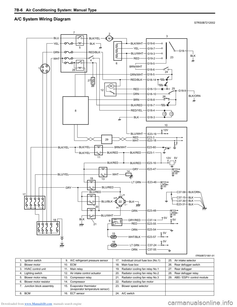
A/C System Wiring DiagramS7RS0B7212002
BLK/REDBLK/RED
BLK/YELBLK/YEL
BLK/YEL
BRN/WHT
12V5V
5V 5V
5V11
E23-1
E23-60
BLK/REDBLK/REDE23-16
E23-57WHT/BLK
9
13
E23-55C37-14GRY/REDRED
BLK
ORN
E23-47 GRY
WHTBLU/YEL
RED/BLK
14 3
1
15
5
7
BLK
2
M
12VBLU/WHTE23-19
C37-24
C37-55ORN
5V
LT GRN16
G18-3
G18-4
G18-7
G18-8
G18-10
G18-13
G18-5
G18-6
G19-5
G19-2
G19-3
G19-7
G19-6
G19-1
G18-9
G18-14
BLK/WHT
YEL
BLU/WHT
RED
BRN/WHT
GRN/WHT
RED/BLK
RED
GRN
BRN
BLK/RED
RED/YEL
BLK
BLK/YEL
BLK/ORN
4
6
12
10
M
E23-54
REDWHTE23-3E23-18
17 18
LT GRNE23-46
L+
L–
H–
H
+
BLU/RED
BLK
BLU/WHTBLK
BLU/BLK
20
GRN
GRY
E23-48
19
21
22
BLU/REDC37-58
C37-15 C37-30
BLK/ORN
BLKBLKE23-31 BLK
BLU
YEL
GRN
WHT
23
24
26 25
28
27
8
29
I7RS0B721001-01
1. Ignition switch
9. A/C refrigerant pressure sensor 17. I ndividual circuit fuse box (No.1) 25. Air intake selector
2. Blower motor 10. ECM 18. Main fuse box 26. Rear defogger switch
3. HVAC control unit 11. Main relay 19. Radiator cooling fan relay No.1 27. Rear defogger
4. Lighting switch 12. Air intake control actuator 20. Radiator cooling fan relay No.2 28. Rear defogger relay
5. Blower motor relay 13. Compressor relay 21. Radiator cooling fan relay No.3 29. ABS / ESP ® control module
6. Blower motor resistor 14. Compressor 22. Radiator cooling fan motor
7. Junction block assembly 15. Evaporator thermistor (evaporator temperature sensor)23. Blower speed selector
8. BCM 16. ECT sensor 24. A/C switch
Page 982 of 1496
Downloaded from www.Manualslib.com manuals search engine 7B-34 Air Conditioning System: Automatic Type
Automatic Type
Precautions
A/C System CautionS7RS0B7220001
Refer to “A/C System Caution”.
Precautions in Diagnosing TroubleS7RS0B7220002
• Do not disconnect couplers from HVAC control module, battery cable from battery, HVAC control module ground
wire harness from body or main fuse before confirming diagnostic information (diagnostic trouble code) stored in
HVAC control module memory.
• Diagnostic information (diagnostic trouble code) stored in HVAC control module can be checked by display of HVAC
control module. Also, it can be checked by using SU ZUKI scan tool. Before checking diagnostic information
(diagnostic trouble code), read this manual and operator's manual for SUZUKI scan tool to know how to read
diagnostic information (diagnostic trouble code).
• When trouble is diagnosed using diagnostic information (diagnostic trouble code) on display of HVAC control
module, keep in your mind that each diagnostic inform ation (diagnostic trouble code) has priority, and only
diagnostic information (diagnostic troub le code) which has the highest priority is indicated. Therefore, after
troubleshooting the malfunction, make sure if there exists any other diagnostic information (diagnostic trouble
code).
• Be sure to read “Precautions for Electrical Circuit Service in Section 00” before inspection.
Precautions on Servicing A/C SystemS7RS0B7220003
Refer to “Precautions on Servicing A/C System”.
General Description
Auto A/C System DescriptionS7RS0B7221001
The automatic type air conditioning system (auto A/C) is pr ovided with the function to automatically control the inside
air temperature, fan speed, air flow outl et direction and air intake position by HVAC control module in addition to
functions of the manual type air conditioning system (manua l A/C). Once the inside air temperature is set using the
temperature selector, HVAC control module automatically controls the inside air temperature at the constant level at all
times based on the inside air temperature, outside ai r temperature, amount of sunlight and engine coolant
temperature detected respectively by the inside air te mperature sensor, outside air temperature sensor, sunload
sensor and ECT sensor. At this time, “FULL AUTO A/ C” appears on the display of HVAC control module.
With the air intake selector pushed in the above state, it is possible to select any position of the air intake actuator.
Then, “FULL AUTO A/C” on the display changes to “AUTO A/C”.
Page 983 of 1496
Downloaded from www.Manualslib.com manuals search engine Air Conditioning System: Automatic Type 7B-35
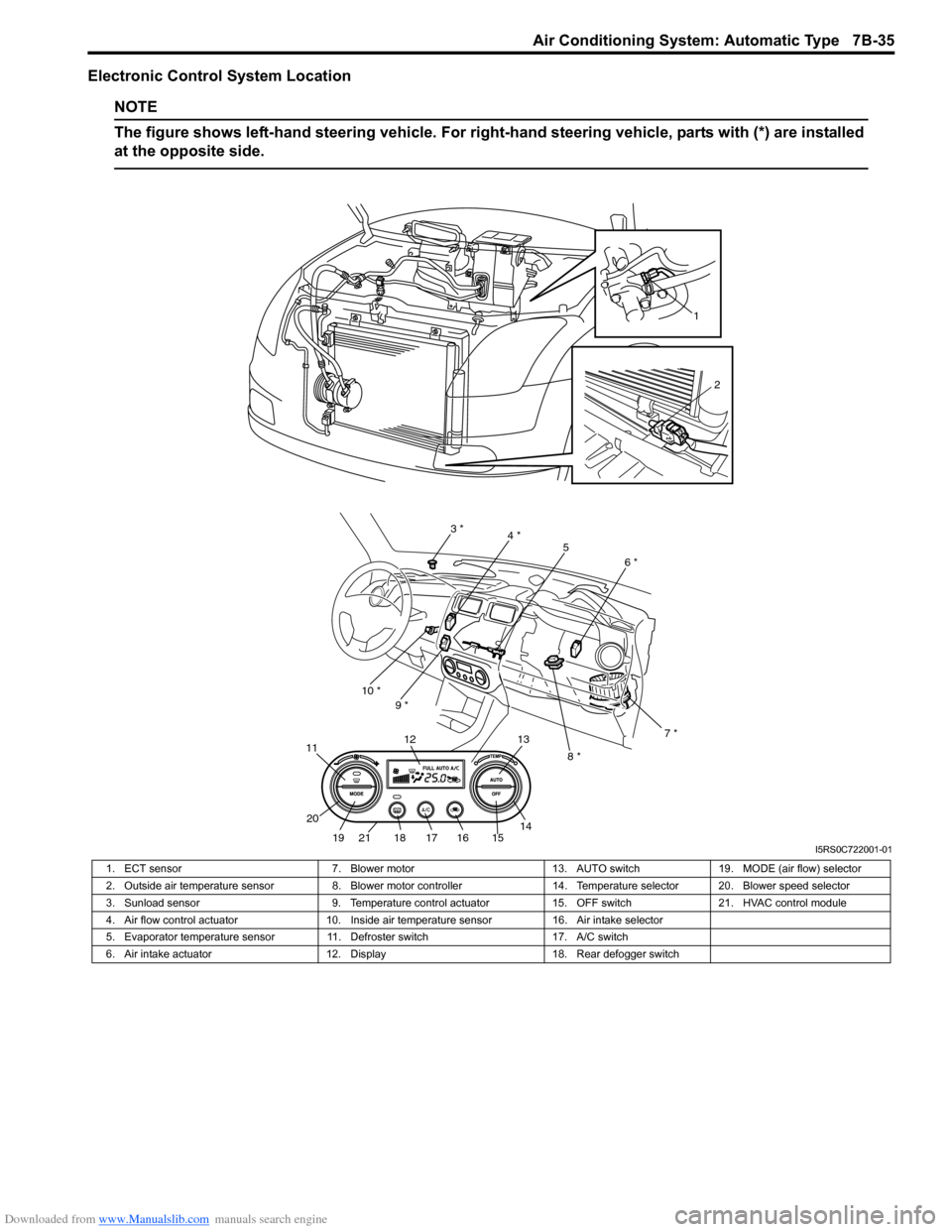
Electronic Control System Location
NOTE
The figure shows left-hand steering vehicle. For right-hand steering vehicle, parts with (*) are installed
at the opposite side.
1
2
3 * 4 *
5
6 *
7 *
8 *
9 *
10 *
21
11
12 13
14
15161718
19
20
I5RS0C722001-01
1. ECT sensor
7. Blower motor13. AUTO switch19. MODE (air flow) selector
2. Outside air temperature sensor 8. Blower motor controller 14. Temperature selector 20. Blower speed selector
3. Sunload sensor 9. Temperature control actuator15. OFF switch21. HVAC control module
4. Air flow control actuator 10. Inside air temperature sensor 16. Air intake selector
5. Evaporator temperature sensor 11. Defroster switch 17. A/C switch
6. Air intake actuator 12. Display 18. Rear defogger switch
Page 984 of 1496
Downloaded from www.Manualslib.com manuals search engine 7B-36 Air Conditioning System: Automatic Type
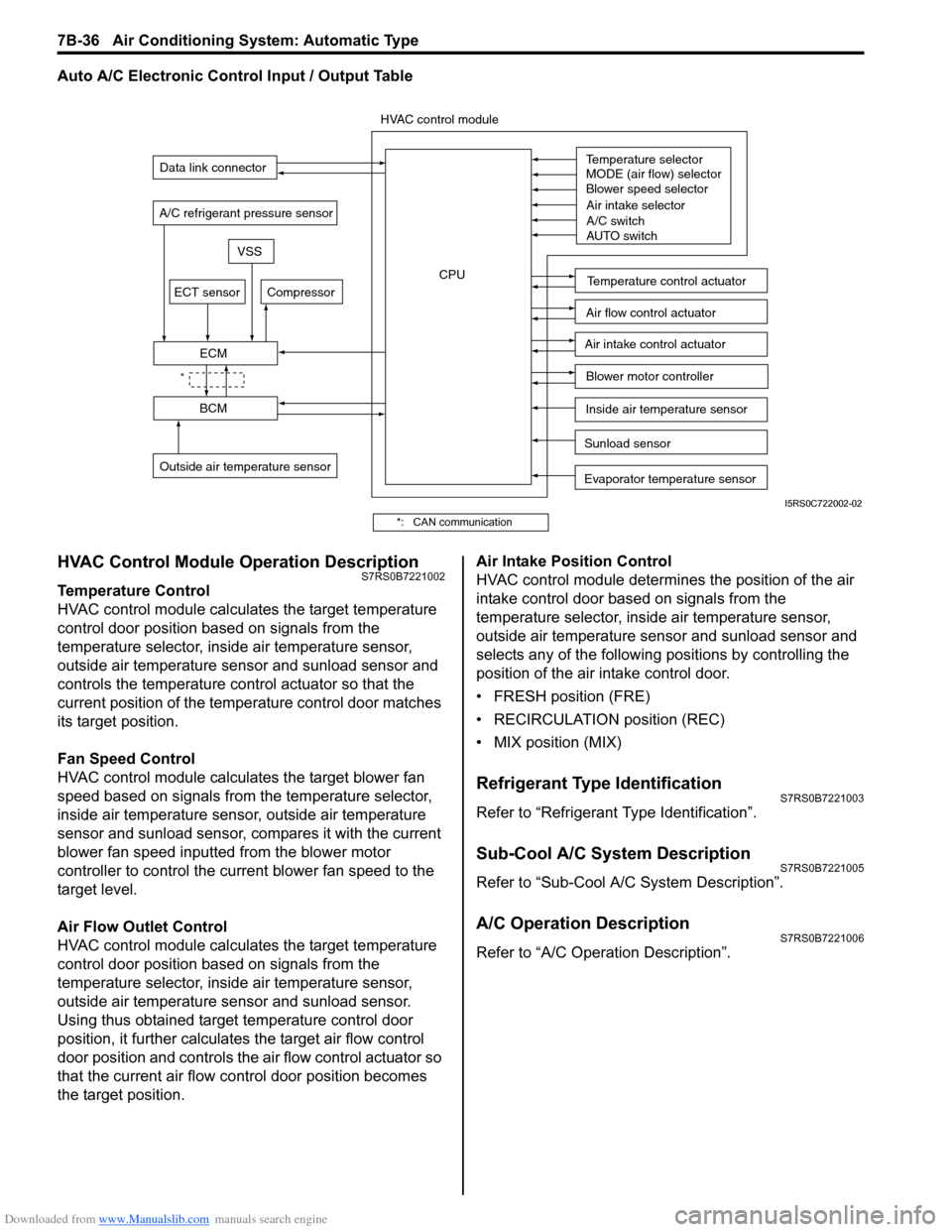
Auto A/C Electronic Control Input / Output Table
HVAC Control Module Operation DescriptionS7RS0B7221002
Temperature Control
HVAC control module calculates the target temperature
control door position based on signals from the
temperature selector, inside air temperature sensor,
outside air temperature sensor and sunload sensor and
controls the temperature control actuator so that the
current position of the temperature control door matches
its target position.
Fan Speed Control
HVAC control module calculates the target blower fan
speed based on signals from the temperature selector,
inside air temperature sensor, outside air temperature
sensor and sunload sensor, compares it with the current
blower fan speed inputted from the blower motor
controller to control the current blower fan speed to the
target level.
Air Flow Outlet Control
HVAC control module calculates the target temperature
control door position based on signals from the
temperature selector, inside air temperature sensor,
outside air temperature sensor and sunload sensor.
Using thus obtained target temperature control door
position, it further calculates the target air flow control
door position and controls the ai r flow control actuator so
that the current air flow c ontrol door position becomes
the target position. Air Intake Position Control
HVAC control module determines the position of the air
intake control door based on signals from the
temperature selector, inside air temperature sensor,
outside air temperature sensor and sunload sensor and
selects any of the following positions by controlling the
position of the air intake control door.
• FRESH position (FRE)
• RECIRCULATION position (REC)
• MIX position (MIX)
Refrigerant Type IdentificationS7RS0B7221003
Refer to “Refrigerant Type Identification”.
Sub-Cool A/C System DescriptionS7RS0B7221005
Refer to “Sub-Cool A/C System Description”.
A/C Operation DescriptionS7RS0B7221006
Refer to “A/C Operation Description”.
Sunload sensor
Outside air temperature sensor Evaporator temperature sensor
A/C refrigerant pressure sensor
Temperature selector
MODE (air flow) selector
Blower speed selector
Air intake selector
AUTO switch
A/C switch
Compressor
Blower motor controller
Temperature control actuator
Air flow control actuator
Air intake control actuator
BCM
ECM
Data link connector
HVAC control module
CPU
ECT sensor
Inside air temperature sensor
VSS
*
I5RS0C722002-02
*: CAN communication
Page 987 of 1496
Downloaded from www.Manualslib.com manuals search engine Air Conditioning System: Automatic Type 7B-39
Diagnostic Information and Procedures
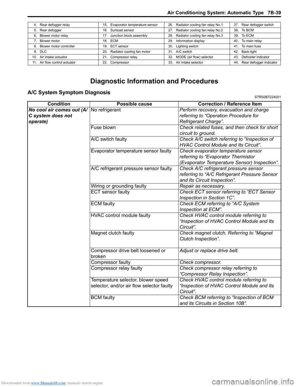
A/C System Symptom DiagnosisS7RS0B7224001
4. Rear defogger relay 15. Evaporator temperature sensor 26. Radiator cooling fan relay No.1 37. Rear defogger switch
5. Rear defogger 16. Sunload sensor 27. Radiator cooling fan relay No.2 38. To BCM
6. Blower motor relay 17. Junction block assembly 28. Radiator cooling fan relay No.3 39. To ECM
7. Blower motor 18. ECM 29. Information display 40. To main relay
8. Blower motor controller 19. ECT sensor 30. Lighting switch 41. To main fuse
9. DLC 20. Radiator cooling fan motor 31. A/C switch 42. Back-light
10. Air intake actuator 21. Compressor relay 32. MODE (air flow) selector 43. Defroster indicator 11. Air flow control actuator 22. Compressor 33. Air intake selector 44. Rear defogger indicator
Condition Possible cause Correction / Reference Item
No cool air comes out (A/
C system does not
operate) No refrigerant
Perform recovery, evacuation and charge
referring to “Operation Procedure for
Refrigerant Charge”.
Fuse blown Check related fuses, and then check for short
circuit to ground.
A/C switch faulty Check A/C switch referring to “Inspection of
HVAC Control Module and Its Circuit”.
Evaporator temperature sensor faulty Check evaporator temperature sensor
referring to “Evaporator Thermistor
(Evaporator Temperature Sensor) Inspection”.
A/C refrigerant pressure sensor faulty Check A/C refrigerant pressure sensor
referring to “A/C Refrigerant Pressure Sensor
and Its Circuit Inspection”.
Wiring or grounding faulty Repair as necessary.
ECT sensor faulty Check ECT sensor referring to “ECT Sensor
Inspection in Section 1C”.
ECM faulty Check ECM referring to “A/C System
Inspection at ECM”.
HVAC control module faulty Check HVAC control module referring to
“Inspection of HVAC Control Module and Its
Circuit”.
Magnet clutch faulty Check magnet clutch. Referring to “Magnet
Clutch Inspection”.
Compressor drive belt loosened or
broken Adjust or replace drive belt.
Compressor faulty Check compressor.
Compressor relay faulty Check compressor relay referring to
“Compressor Relay Inspection”.
Temperature selector, blower speed
selector, and/or air flow selector faulty Check HVAC control module referring to
“Inspection of HVAC Control Module and Its
Circuit”.
BCM faulty Check BCM referring to “Inspection of BCM
and its Circuits in Section 10B”.