Main bearing SUZUKI SWIFT 2005 2.G Service Owner's Manual
[x] Cancel search | Manufacturer: SUZUKI, Model Year: 2005, Model line: SWIFT, Model: SUZUKI SWIFT 2005 2.GPages: 1496, PDF Size: 34.44 MB
Page 607 of 1496

Downloaded from www.Manualslib.com manuals search engine Electronic Stability Program: 4F-33
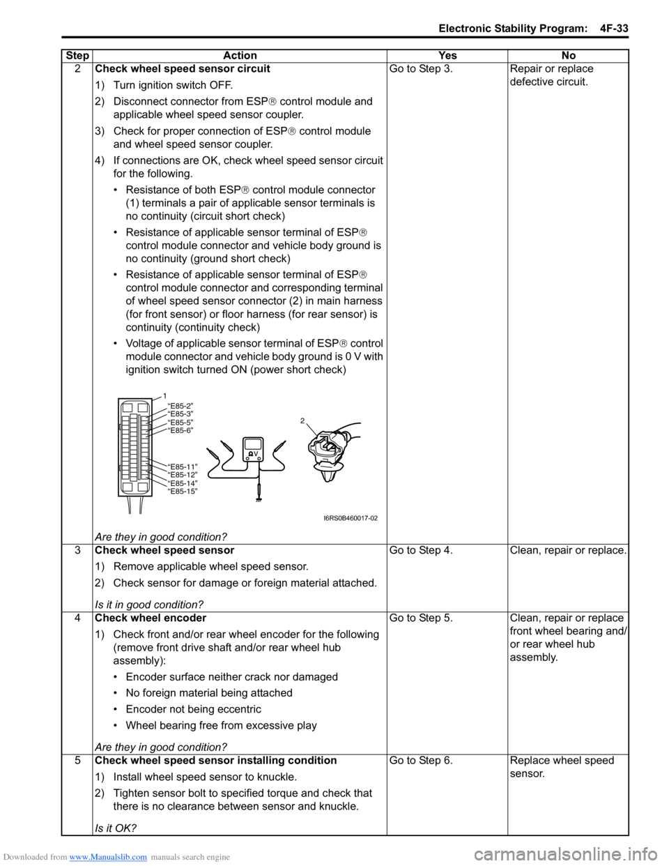
2Check wheel speed sensor circuit
1) Turn ignition switch OFF.
2) Disconnect connector from ESP ® control module and
applicable wheel speed sensor coupler.
3) Check for proper connection of ESP ® control module
and wheel speed sensor coupler.
4) If connections are OK, che ck wheel speed sensor circuit
for the following.
• Resistance of both ESP ® control module connector
(1) terminals a pair of app licable sensor terminals is
no continuity (circuit short check)
• Resistance of applicable sensor terminal of ESP ®
control module connector and vehicle body ground is
no continuity (ground short check)
• Resistance of applicable sensor terminal of ESP ®
control module connector and corresponding terminal
of wheel speed sensor connector (2) in main harness
(for front sensor) or floor harness (for rear sensor) is
continuity (continuity check)
• Voltage of applicable sensor terminal of ESP ® control
module connector and vehicle body ground is 0 V with
ignition switch turned ON (power short check)
Are they in good condition? Go to Step 3. Repair or replace
defective circuit.
3 Check wheel speed sensor
1) Remove applicable wheel speed sensor.
2) Check sensor for damage or foreign material attached.
Is it in good condition? Go to Step 4. Clean, repair or replace.
4 Check wheel encoder
1) Check front and/or rear wheel encoder for the following
(remove front drive shaft and/or rear wheel hub
assembly):
• Encoder surface neither crack nor damaged
• No foreign material being attached
• Encoder not being eccentric
• Wheel bearing free from excessive play
Are they in good condition? Go to Step 5. Clean, repair or replace
front wheel bearing and/
or rear wheel hub
assembly.
5 Check wheel speed sensor installing condition
1) Install wheel speed sensor to knuckle.
2) Tighten sensor bolt to specified torque and check that
there is no clearance between sensor and knuckle.
Is it OK? Go to Step 6. Replace wheel speed
sensor.
Step Action Yes No
1
2“E85-2”“E85-3”“E85-5”
“E85-6”
“E85-11”
“E85-12”
“E85-14”
“E85-15”
I6RS0B460017-02
Page 878 of 1496

Downloaded from www.Manualslib.com manuals search engine 6B-7 Steering Wheel and Column:
Steering Column Removal and InstallationS7RS0B6206006
CAUTION!
Once the steering column is removed from
the vehicle, the column is extremely
susceptible to damage.
• Dropping the column assembly on its end could collapse the steering shaft or loosen
the plastic shear pins which maintain
column length.
• Leaning on the column assembly could cause it to bend or deform.
Any of the damage could impair the column’s
collapsible design.
Steering column mounting nuts should not
be loosened with steering shaft joint upper
side bolt tightened as this could cause
damage to shaft joint bearing.
NOTE
When servicing steering column or any
column-mounted component, remove
steering wheel. But when removing steering
column simply to gain access to instrument
panel components, leave steering wheel
installed on steering column.
Removal
WARNING!
Never rest a steering column assembly on
the steering wheel with the air bag (inflator)
module face down and column vertical.
Otherwise, personal injury may result.
1) Disconnect negative (–) cable at battery.
2) Disable air bag system. Re fer to “Disabling Air Bag
System in Section 8B”.
3) Remove steering wheel and contact coil cable assembly referring to “S teering Wheel Removal and
Installation” and “Contact Coil Cable Assembly
Removal and Installation”.
4) Detach lighting switch and wiper switch from steering column.
5) Remove immobilizer cont rol module from steering
column, referring to “Immo bilizer Control Module
(ICM) Removal and Installation in Section 10C”.
6) Remove steering column hole cover.
7) Remove steering joint cover.
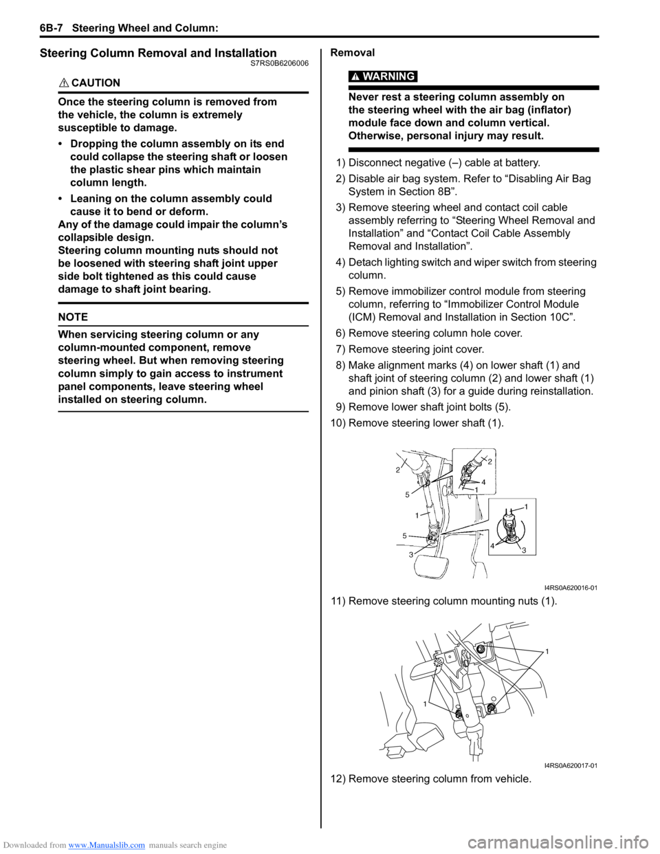
8) Make alignment marks (4) on lower shaft (1) and shaft joint of steering column (2) and lower shaft (1)
and pinion shaft (3) for a guide during reinstallation.
9) Remove lower shaf t joint bolts (5).
10) Remove steering lower shaft (1).
11) Remove steering column mounting nuts (1).
12) Remove steering column from vehicle.
I4RS0A620016-01
1
1
I4RS0A620017-01