caliper pin SUZUKI SWIFT 2005 2.G Service Owner's Manual
[x] Cancel search | Manufacturer: SUZUKI, Model Year: 2005, Model line: SWIFT, Model: SUZUKI SWIFT 2005 2.GPages: 1496, PDF Size: 34.44 MB
Page 531 of 1496
Downloaded from www.Manualslib.com manuals search engine Rear Brakes: 4C-7
Assembly
CAUTION!
• Wash each part cleanly before installation in the same fluid as the one used in master
cylinder reservoir.
• Never use other fluid or thinner.
• Before installing caliper to brake caliper carrier, install slide pins with grease
applied into carrier hole and check for its
smooth movement in thrust direction.
• Before installing piston seal to cylinder, apply fluid to them.
• Install a piston seal into groove in cylinder securely making sure that it is not twisted.
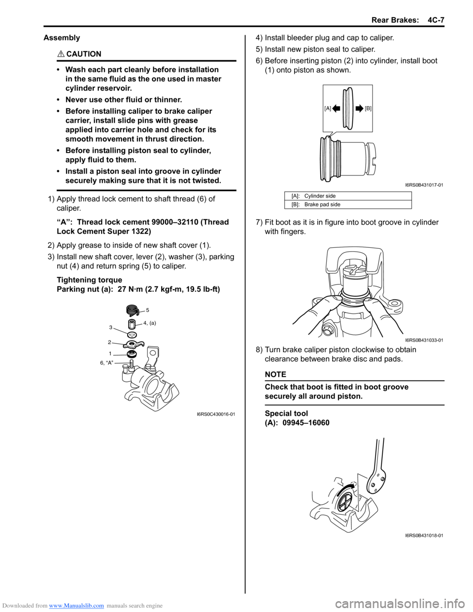
1) Apply thread lock cement to shaft thread (6) of caliper.
“A”: Thread lock cement 99000–32110 (Thread
Lock Cement Super 1322)
2) Apply grease to inside of new shaft cover (1).
3) Install new shaft cover, leve r (2), washer (3), parking
nut (4) and return spring (5) to caliper.
Tightening torque
Parking nut (a): 27 N·m (2.7 kgf-m, 19.5 lb-ft) 4) Install bleeder plug and cap to caliper.
5) Install new piston seal to caliper.
6) Before inserting piston (2) into cylinder, install boot
(1) onto piston as shown.
7) Fit boot as it is in figure into boot groove in cylinder with fingers.
8) Turn brake caliper piston clockwise to obtain clearance between brake disc and pads.
NOTE
Check that boot is fitted in boot groove
securely all around piston.
Special tool
(A): 09945–16060
5
4, (a)
2
3
1
6, “A”
I6RS0C430016-01
[A]: Cylinder side
[B]: Brake pad side
[A] [B]
I6RS0B431017-01
I6RS0B431033-01
I6RS0B431018-01
Page 532 of 1496
Downloaded from www.Manualslib.com manuals search engine 4C-8 Rear Brakes:
Rear Disc Brake Caliper InspectionS7RS0B4306006
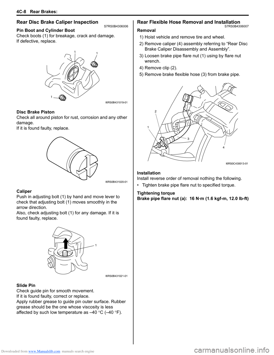
Pin Boot and Cylinder Boot
Check boots (1) for breakage, crack and damage.
If defective, replace.
Disc Brake Piston
Check all around piston for rust, corrosion and any other
damage.
If it is found faulty, replace.
Caliper
Push in adjusting bolt (1) by hand and move lever to
check that adjusting bolt (1) moves smoothly in the
arrow direction.
Also, check adjusting bolt (1) for any damage. If it is
found faulty, replace.
Slide Pin
Check guide pin for smooth movement.
If it is found faulty, correct or replace.
Apply rubber grease to guide pin outer surface. Rubber
grease should be the one whose viscosity is less
affected by such low temperature as –40 °C (–40 ° F).
Rear Flexible Hose Removal and InstallationS7RS0B4306007
Removal
1) Hoist vehicle and remove tire and wheel.
2) Remove caliper (4) assembly referring to “Rear Disc Brake Caliper Disassembly and Assembly”.
3) Loosen brake pipe flare nut (1) using by flare nut wrench.
4) Remove clip (2).
5) Remove brake flexible hose (3) from brake pipe.
Installation
Install reverse order of removal nothing the following.
• Tighten brake pipe flare nut to specified torque.
Tightening torque
Brake pipe flare nut (a): 16 N·m (1.6 kgf-m, 12.0 lb-ft)
1 1
1
I6RS0B431019-01
I6RS0B431020-01
1
I6RS0B431021-01
1
2
3
4
I6RS0C430013-01
Page 534 of 1496
Downloaded from www.Manualslib.com manuals search engine 4C-10 Rear Brakes:
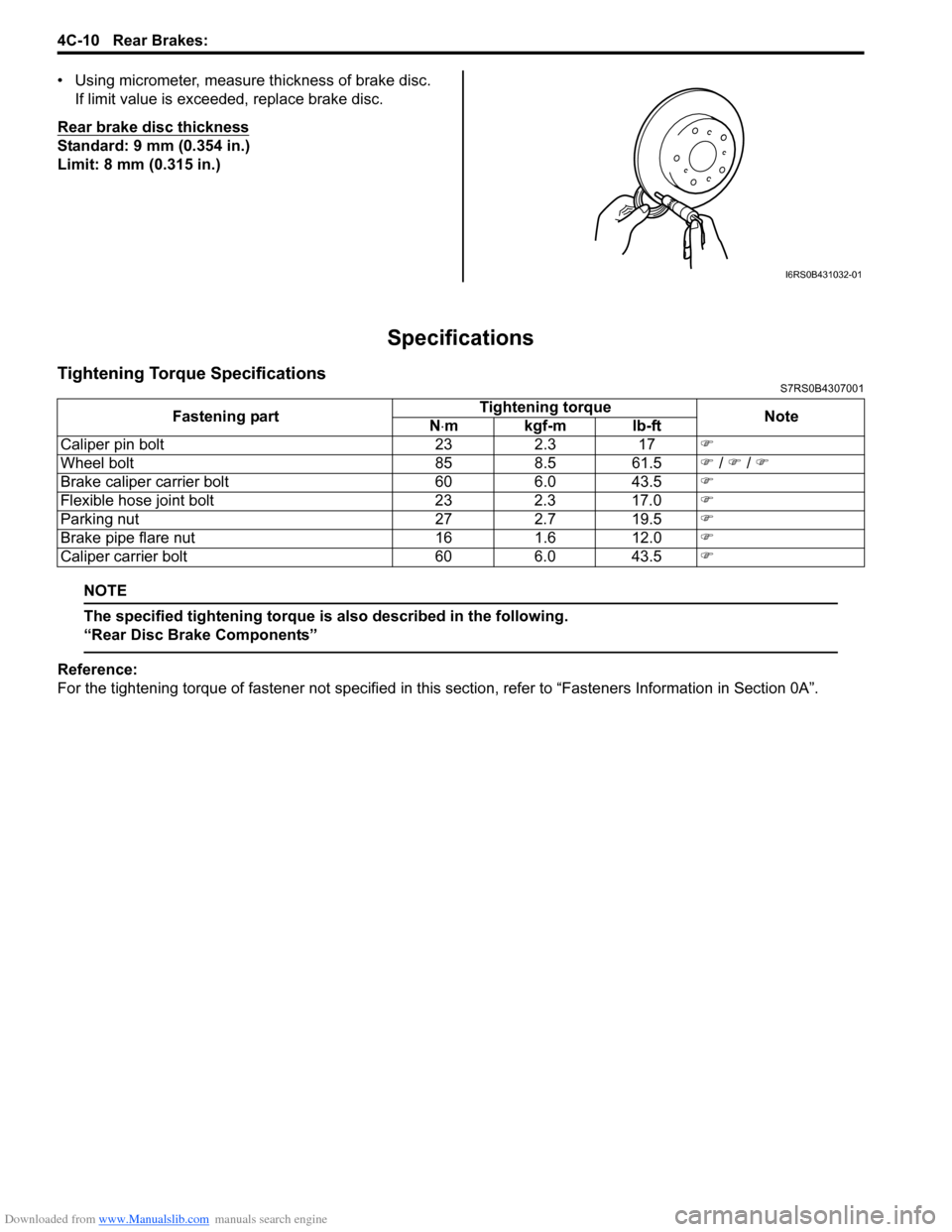
• Using micrometer, measure thickness of brake disc.If limit value is exceeded, replace brake disc.
Rear brake disc thickness
Standard: 9 mm (0.354 in.)
Limit: 8 mm (0.315 in.)
Specifications
Tightening Torque SpecificationsS7RS0B4307001
NOTE
The specified tightening torque is also described in the following.
“Rear Disc Brake Components”
Reference:
For the tightening torque of fastener not specified in this section, refer to “Fasteners Information in Section 0A”.
I6RS0B431032-01
Fastening part Tightening torque
Note
N ⋅mkgf-mlb-ft
Caliper pin bolt 23 2.3 17 �)
Wheel bolt 85 8.5 61.5 �) / �) / �)
Brake caliper carrier bolt 60 6.0 43.5 �)
Flexible hose joint bolt 23 2.3 17.0 �)
Parking nut 27 2.7 19.5 �)
Brake pipe flare nut 16 1.6 12.0 �)
Caliper carrier bolt 60 6.0 43.5 �)
Page 537 of 1496
Downloaded from www.Manualslib.com manuals search engine Parking Brake: 4D-2
Repair Instructions
Parking Brake Inspection and AdjustmentS7RS0B4406001
Inspection
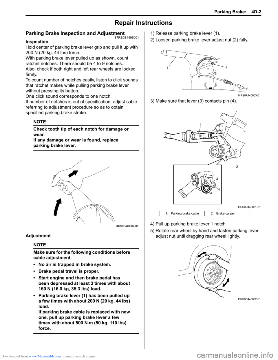
Hold center of parking brake lever grip and pull it up with
200 N (20 kg, 44 lbs) force.
With parking brake lever pulled up as shown, count
ratchet notches. There should be 4 to 9 notches.
Also, check if both right and left rear wheels are locked
firmly.
To count number of notches easily, listen to click sounds
that ratchet makes while pulling parking brake lever
without pressing its button.
One click sound corresponds to one notch.
If number of notches is out of specification, adjust cable
referring to adjustment procedure so as to obtain
specified parking brake stroke.
NOTE
Check tooth tip of each notch for damage or
wear.
If any damage or wear is found, replace
parking brake lever.
Adjustment
NOTE
Make sure for the following conditions before
cable adjustment.
• No air is trapped in brake system.
• Brake pedal travel is proper.
• Start engine and then brake pedal has been depressed at least 3 times with about
160 N (16.0 kg, 35.3 lbs) load.
• Parking brake lever (1) has been pulled up a few times with about 200 N (20 kg, 44 lbs)
load.
If parking brake cable is replaced with new
one, pull up parking brake lever a few
times with about 500 N ⋅m (50 kg, 110 lbs)
force.
1) Release parking brake lever (1).
2) Loosen parking brake lever adjust nut (2) fully.
3) Make sure that lever (3) contacts pin (4).
4) Pull up parking brake lever 1 notch.
5) Rotate rear wheel by hand and fasten parking lever adjust nut until dragging rear wheel lightly.
I4RS0B440002-01
1. Parking brake cable 2. Brake caliper
I4RS0A440003-01
I6RS0C440001-01
I6RS0C440002-01
Page 578 of 1496
Downloaded from www.Manualslib.com manuals search engine 4F-4 Electronic Stability Program:
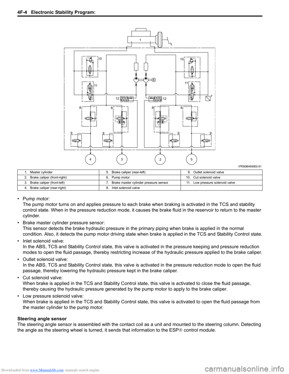
• Pump motor:The pump motor turns on and applies pressure to each brake when braking is activated in the TCS and stability
control state. When in the pressure reduction mode, it causes the brake fluid in the reservoir to return to the master
cylinder.
• Brake master cylinder pressure sensor: This sensor detects the brake hydraulic pressure in th e primary piping when brake is applied in the normal
condition. Also, it detects the pump motor driving state wh en brake is applied in the TCS and Stability Control state.
• Inlet solenoid valve: In the ABS, TCS and Stability Control stat e, this valve is activated in the pressure keeping and pressure reduction
modes to open the fluid passage, thereby restricting increase of the hydraulic pressure applied to the brake caliper.
• Outlet solenoid valve: In the ABS, TCS and Stability Control state, this valve is activated in the pressure reduction mode to open the fluid
passage, thereby lowering the hydraulic pressure kept in the brake caliper.
• Cut solenoid valve: When brake is applied in the TCS and Stability Control state, this valve is activated to close the fluid passage,
thereby causing the hydraulic pressure generated by the pump motor to apply to the brake caliper.
• Low pressure solenoid valve: When brake is applied in the TCS and Stab ility Control state, this valve is activated to open the fluid passage from
the master cylinder to the pump motor.
Steering angle sensor
The steering angle sensor is assembled with the contact co il as a unit and mounted to the steering column. Detecting
the angle as the steering wheel is turned, it sends that information to the ESP ® control module.
1
10 10
11 11
6
7
12 12
8 8 88
9 9 9
9
43 5 2
I7RS0B460002-01
1. Master cylinder 5. Brake caliper (rear-left)9. Outlet solenoid valve
2. Brake caliper (front-right) 6. Pump motor10. Cut solenoid valve
3. Brake caliper (front-left) 7. Brake master cylinder pressure sensor 11. Low pressure solenoid valve
4. Brake caliper (rear-right) 8. Inlet solenoid valve
Page 871 of 1496

Downloaded from www.Manualslib.com manuals search engine Steering General Diagnosis: 6A-2
Diagnostic Information and Procedures
Steering Symptom DiagnosisS7RS0B6104001
ConditionPossible cause Correction / Reference Item
Hard steering Tire not adequately inflated Inflate tires to proper pressure.
Malfunction of power steering system Check and correct.
Bind in tie-rod end ball studs or lower
ball joints Replace tie-rod end or front suspension arm.
Disturbed front wheel alignment Check and adjust front wheel alignment.
Bind in steering column Repair or replace steering column.
Rack and pinion adjustment Check and adjustment rack and pinion torque.
Too much play in steering Wheel bearings worn Replace wheel bearing.
Loose steering gear case bolts Tighten gear case bolts.
Faulty steering gear case assembly Replace steering gear case assembly.
Worn steering shaft joints Replace joint.
Worn tie-rod ends or tie-rod inside ball
joints Replace tie-rod end or tie-rod.
Worn lower ball joints Replace front suspension control arm.
Rack and pinion adjustment Check and adjustment rack and pinion torque.
Poor return ability Bind in tie-rod end ball studs Replace tie-rod end.
Bind in ball joints Replace front suspension control arm.
Bind in steering column Repair or replace steering column.
Disturbed front end alignment Check and adjust front end alignment.
Faulty steering gear case assembly Replace steering gear case assembly.
Tires not adequately inflated Adjust tire pressure.
Rack and pinion adjustment Check and adjustment rack and pinion torque.
Rack and pinion noise
(Rattle or chuckle) Loose steering gear case bolts
Tighten steering gear case bolts.
Rack and pinion adjustment Check and adjustment rack and pinion torque.
Faulty steering gear case assembly Replace steering gear case assembly.
Broken or other wise damaged wheel
bearing(s) Replace wheel bearing(s).
Wander or poor steering
stability Mismatched or uneven tires
Replace or inflate tires to proper pressure.
Loosen ball joints and tie-rod ends Replace suspension control arm or tie-rod end.
Faulty struts or mountings Replace strut or repair mounting.
Loose stabilizer bar Tighten or replace stabilizer bar or bush.
Broken or sagging springs Replace spring.
Rack and pinion adjustment Check and adjustment rack and pinion torque.
Disturbed front wheel alignment Check and adjust front wheel alignment.
Faulty steering gear case assembly Replace steering gear case assembly.
Erratic steering when
braking Worn wheel bearing(s)
Replace wheel bearing(s).
Broken or sagging spring(s) Replace coil spring(s).
Wheel tires are inflated unequally Inflate tires to proper pressure.
Disturbed front wheel alignment Check and adjust front wheel alignment.
Brakes not working in unison Check and repair brake system.
Leaking caliper Repair or replace caliper.
Warped discs Replace brake disc.
Badly worn brake pads Replace brake pads.