driver info SUZUKI SWIFT 2005 2.G Service Owner's Manual
[x] Cancel search | Manufacturer: SUZUKI, Model Year: 2005, Model line: SWIFT, Model: SUZUKI SWIFT 2005 2.GPages: 1496, PDF Size: 34.44 MB
Page 179 of 1496
Downloaded from www.Manualslib.com manuals search engine Engine General Information and Diagnosis: 1A-129
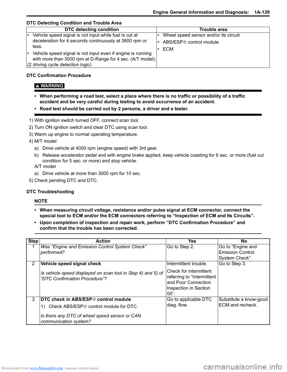
DTC Detecting Condition and Trouble Area
DTC Confirmation Procedure
WARNING!
• When performing a road test, select a place where there is no traffic or possibility of a traffic accident and be very careful during testing to avoid occurrence of an accident.
• Road test should be carried out by 2 persons, a driver and a tester.
1) With ignition switch turned OFF, connect scan tool.
2) Turn ON ignition switch and clear DTC using scan tool.
3) Warm up engine to normal operating temperature.
4) M/T model
a) Drive vehicle at 4000 rpm (e ngine speed) with 3rd gear.
b) Release accelerator pedal and with engine brake applied, keep vehicle coasting for 6 sec. or more (fuel cut condition for 5 sec. or more) and stop vehicle.
A/T model
a) Drive vehicle at more than 3000 rpm for 10 sec.
5) Check pending DTC and DTC.
DTC Troubleshooting
NOTE
• When measuring circuit voltage, resistance and/ or pulse signal at ECM connector, connect the
special tool to ECM and/or the ECM connectors re ferring to “Inspection of ECM and Its Circuits”.
• Upon completion of inspection and repair work, perform “DTC Confirmation Procedure” and confirm that the trouble has been corrected.
DTC detecting condition Trouble area
• Vehicle speed signal is not input while fuel is cut at deceleration for 4 seconds continuously at 3600 rpm or
less.
• Vehicle speed signal is not input even if engine is running with more than 3000 rpm at D-Range for 4 sec. (A/T model).
(2 driving cycle detection logic) • Wheel speed sensor and/or its circuit
• ABS/ESP®
control module
•ECM
Step Action YesNo
1 Was “Engine and Emission Control System Check”
performed? Go to Step 2.
Go to “Engine and
Emission Control
System Check”.
2 Vehicle speed signal check
Is vehicle speed displayed on scan tool in Step 4) and 5) of
“DTC Confirmation Procedure”? Intermittent trouble.
Check for intermittent
referring to “Intermittent
and Poor Connection
Inspection in Section
00”.Go to Step 3.
3 DTC check in ABS/ESP ® control module
1) Check ABS/ESP ® control module for DTC.
Is there any DTC of wheel speed sensor or CAN
communication system? Go to applicable DTC
diag. flow.
Substitute a know-good
ECM and recheck.
Page 224 of 1496
Downloaded from www.Manualslib.com manuals search engine 1A-174 Engine General Information and Diagnosis:
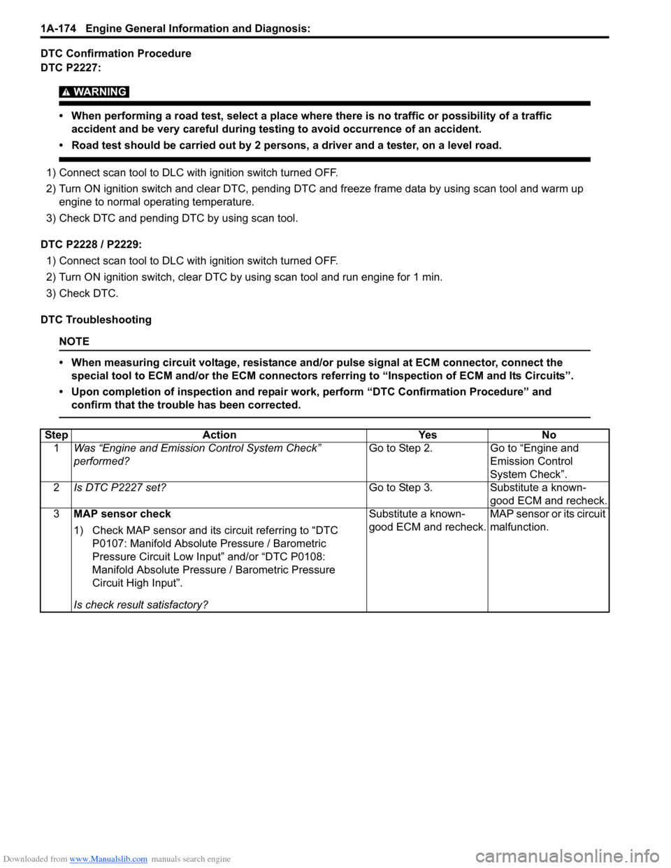
DTC Confirmation Procedure
DTC P2227:
WARNING!
• When performing a road test, select a place where there is no traffic or possibility of a traffic accident and be very careful during testing to avoid occurrence of an accident.
• Road test should be carried out by 2 persons, a driver and a tester, on a level road.
1) Connect scan tool to DLC with ignition switch turned OFF.
2) Turn ON ignition switch and clear DTC, pending DTC and freeze frame data by using scan tool and warm up
engine to normal operating temperature.
3) Check DTC and pending DTC by using scan tool.
DTC P2228 / P2229: 1) Connect scan tool to DLC with ignition switch turned OFF.
2) Turn ON ignition switch, clear DTC by using scan tool and run engine for 1 min.
3) Check DTC.
DTC Troubleshooting
NOTE
• When measuring circuit voltage, resistance and/ or pulse signal at ECM connector, connect the
special tool to ECM and/or the ECM connectors re ferring to “Inspection of ECM and Its Circuits”.
• Upon completion of inspection and repair work, perform “DTC Confirmation Procedure” and confirm that the trouble has been corrected.
Step Action YesNo
1 Was “Engine and Emission Control System Check”
performed? Go to Step 2.
Go to “Engine and
Emission Control
System Check”.
2 Is DTC P2227 set? Go to Step 3.Substitute a known-
good ECM and recheck.
3 MAP sensor check
1) Check MAP sensor and its circuit referring to “DTC
P0107: Manifold Absolute Pressure / Barometric
Pressure Circuit Low Input” and/or “DTC P0108:
Manifold Absolute Pressure / Barometric Pressure
Circuit High Input”.
Is check result satisfactory? Substitute a known-
good ECM and recheck.
MAP sensor or its circuit
malfunction.
Page 496 of 1496

Downloaded from www.Manualslib.com manuals search engine 4-ii Table of Contents
Repair Instructions ..............................................4D-2Parking Brake Inspection and Adjustment ..........4D-2
Parking Brake Cable Removal and Installation ......................................................... 4D-3
Parking Brake Lever Removal and Installation ....4D-3
Specifications .... ...................................................4D-4
Tightening Torque Specifications ........................4D-4
ABS ........................................... .................4E-1
Precautions........................................................... 4E-1
Precautions in Diagnosing Troubles ................... 4E-1
Precautions in On-Vehicle Service...................... 4E-1
Precautions in Hydraulic Unit Operation Check ................................................................ 4E-1
General Description ............................................. 4E-2 ABS Description .................................................. 4E-2
ABS Hydraulic Unit / Control Module Assembly Description ....................................... 4E-2
CAN Communication System Description........... 4E-3
Schematic and Routing Diagram ........................ 4E-4 ABS Schematic ................................................... 4E-4
ABS Wiring Circuit Diagram ................................ 4E-5
Component Location ........... ................................ 4E-7
ABS Components Location ................................. 4E-7
Front Wheel Speed Sensor Components Location ............................................................ 4E-7
Rear Wheel Speed Sensor Components Location ............................................................ 4E-8
Diagnostic Information and Procedures ............ 4E-8 ABS Check .......................................................... 4E-8
ABS Warning Light Check................................. 4E-10
EBD Warning Light (Brake Warning Light) Check .............................................................. 4E-10
DTC Check........................................................ 4E-11
DTC Table ......................................................... 4E-11
DTC Clearance ................................................. 4E-12
Scan Tool Data ................................................. 4E-12
ABS Warning Light Does Not Come ON at Ignition Switch ON .......................................... 4E-13
ABS Warning Light Comes ON Steady ............. 4E-14
EBD Warning Light (Brake Warning Light) Comes ON Steady .......................................... 4E-15
Serial Data Link Circuit Check .......................... 4E-16
DTC C1021, C1022 / C1025, C1026 / C1031, C1032 / C1035, C1036: Right-Front / Left-
Front / Right-Rear / Left-Rear Wheel Speed
Sensor Circuit or Sensor Ring ........................ 4E-18
DTC C1041 / C1045 / C1051 / C1055, DTC C1042 / C1046 / C1052 / C1056: Right-Front
/ Left-Front / Right-Rear / Left-Rear Inlet
Solenoid Circuit, Right-Front / Left-Front /
Right-Rear / Left-Rear Outlet Solenoid
Circuit .............................................................. 4E-20
DTC C1057: Power Source Circuit ................... 4E-21
DTC C1061: ABS Pump Motor and/or Motor Driver Circuit ................................................... 4E-22
DTC C1063: Solenoid Valve Power Supply Driver Circuit ................................................... 4E-23
DTC C1071: ABS Control Module..................... 4E-24 DTC U1073: Control Module Communication
Bus Off ............................................................ 4E-25
DTC U1100: Lost Communication with ECM (Reception Error)............................................. 4E-27
Repair Instructions ............ ................................ 4E-28
ABS Hydraulic Unit Operati on Check................ 4E-28
ABS Hydraulic Unit / Control Module
Assembly Components ...... ............................. 4E-29
ABS Hydraulic Unit / Control Module
Assembly On-Vehicle Inspection .................... 4E-29
ABS Hydraulic Unit / Control Module
Assembly Removal and Inst allation ................ 4E-29
Front / Rear Wheel Speed Sensor On-Vehicle Inspection ........................................................ 4E-31
Front Wheel Speed Sensor Removal and Installation ....................................................... 4E-32
Front Wheel Speed Sensor Inspection ............. 4E-32
Rear Wheel Speed Sensor Removal and Installation ....................................................... 4E-33
Rear Wheel Speed Sensor Inspection .............. 4E-34
Front Wheel Encoder On-Veh icle Inspection .... 4E-34
Front wheel Enco der Removal and
Installation ....................................................... 4E-34
Rear Wheel Encoder On-Veh icle Inspection..... 4E-34
Rear Wheel Encoder Removal and Installation ....................................................... 4E-34
Specifications ..................... ................................ 4E-35
Tightening Torque Specifications ...................... 4E-35
Special Tools and Equipmen t ........................... 4E-35
Special Tool ...................................................... 4E-35
Electronic Stability Prog ram ...................4F-1
Precautions ........................................................... 4F-1
Precautions in Diagnosing Troubles ................... 4F-1
Precautions in On-Vehicle Service...................... 4F-1
Precautions in Hydraulic Unit Operation Check ................................................................ 4F-1
Precautions in Sensor Calibration ....................... 4F-1
Precautions in Speedometer Test or Other Tests ................................................................. 4F-2
General Description ............................................. 4F-2 Electronic Stability Program Description ............. 4F-2
Electronic Stability Program Construction ........... 4F-3
ESP® Hydraulic Unit / Control Module
Assembly Description........................................ 4F-5
Warning Lamp, Indicator Lamp Description ........ 4F-6
CAN Communication System Description........... 4F-6
CAN Communication System For Electronic Stability Program Description ............................ 4F-7
Schematic and Routing Diagram ........................ 4F-8 Electronic Stability Program Schematic .............. 4F-8
Electronic Stability Program Wiring Circuit Diagram............................................................. 4F-9
Component Location ............ ............................. 4F-11
Electronic Stability Program Component
Location........................................................... 4F-11
Diagnostic Information and Procedures .......... 4F-12 Electronic Stability Program System Check ...... 4F-12
ESP® Warning lamp Check .............................. 4F-14
Page 541 of 1496
Downloaded from www.Manualslib.com manuals search engine ABS: 4E-2
General Description
ABS DescriptionS7RS0B4501001
The ABS (Antilock Brake System) controls the fluid
pressure applied to the wheel cylinder of each brake
from the master cylinder so that each wheel is not locked
even when hard braking is applied.
This ABS has also the following function.
While braking is applied, but before ABS control
becomes effective, braking force is distributed between
the front and rear so as to prevent the rear wheels from
being locked too early for better stability of the vehicle.
The main component parts of this ABS include the
following parts in addition to those of the conventional
brake system.
• Wheel speed sensor which senses revolution speed of each wheel and outputs its signal.
• ABS warning light which light s to inform abnormality
when system fails to operate properly.
• ABS hydraulic unit / cont rol module assembly is
incorporated ABS co ntrol module, ABS hydraulic unit
(actuator assembly), solenoid valve power supply
driver (transistor), solenoid valve driver (transistor),
pump motor driver (transistor).
– ABS control module which sends operation signal to ABS hydraulic unit to control fluid pressure
applied to each wheel cylinder based on signal
from each wheel speed sensor so as to prevent
wheel from locking.
– ABS hydraulic unit which operates according to signal from ABS control module to control fluid
pressure applied to wheel cylinder of each 4
wheels.
– Solenoid valve power supp ly driver (transistor)
which supplies power to solenoid valve in ABS
hydraulic unit.
– Solenoid valve driver (transistor) which controls each solenoid valves in ABS hydraulic unit.
– Pump motor driver (transistor) which supplies power to pump motor in ABS hydraulic unit.
This ABS is equipped with Electronic Brake force
Distribution (EBD) system that controls a fluid pressure
of rear wheels to best condition, which is the same
function as that of proportion ing valve, by the signal from
wheel sensor independently of change of load due to
load capacity and so on. An d if the EBD system fails to
operate properly, the brake warning light lights to inform
abnormality.
ABS Hydraulic Unit / Control Module Assembly
Description
S7RS0B4501002
ABS control module is a component of ABS hydraulic
unit / control module asse mbly and has the following
functions.
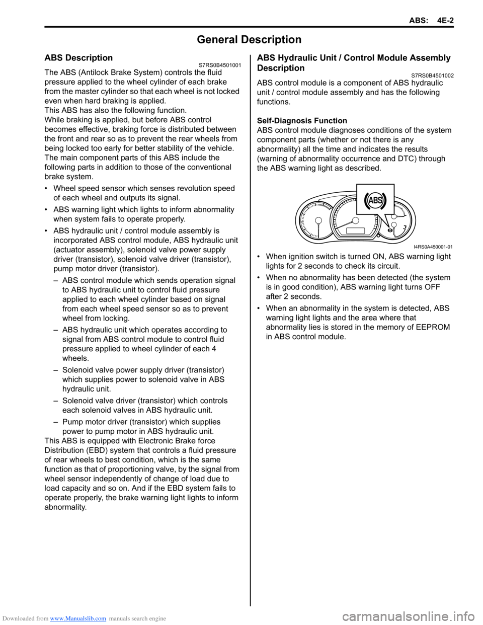
Self-Diagnosis Function
ABS control module diagnose s conditions of the system
component parts (whether or not there is any
abnormality) all the time and indicates the results
(warning of abnormality occurrence and DTC) through
the ABS warning light as described.
• When ignition switch is turned ON, ABS warning light lights for 2 seconds to check its circuit.
• When no abnormality has been detected (the system is in good condition), ABS warning light turns OFF
after 2 seconds.
• When an abnormality in th e system is detected, ABS
warning light lights and the area where that
abnormality lies is stored in the memory of EEPROM
in ABS control module.
1
I4RS0A450001-01
Page 551 of 1496
Downloaded from www.Manualslib.com manuals search engine ABS: 4E-12
DTC ClearanceS7RS0B4504006
WARNING!
When performing a driving test, select a safe
place where there is neither any traffic nor
any traffic accident possibility and be very
careful during testing to avoid occurrence of
an accident.
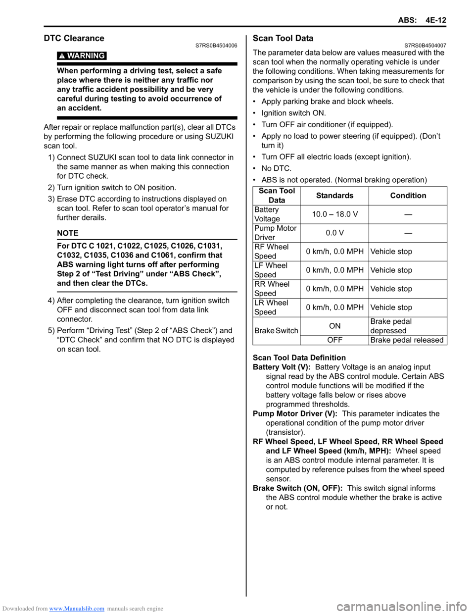
After repair or replace malfunction part(s), clear all DTCs
by performing the following procedure or using SUZUKI
scan tool.
1) Connect SUZUKI scan tool to data link connector in the same manner as when making this connection
for DTC check.
2) Turn ignition switch to ON position.
3) Erase DTC according to instructions displayed on scan tool. Refer to scan tool operator’s manual for
further derails.
NOTE
For DTC C 1021, C1022, C1025, C1026, C1031,
C1032, C1035, C1036 and C1061, confirm that
ABS warning light turns off after performing
Step 2 of “Test Driving” under “ABS Check”,
and then clear the DTCs.
4) After completing the clear ance, turn ignition switch
OFF and disconnect scan tool from data link
connector.
5) Perform “Driving Test” (S tep 2 of “ABS Check”) and
“DTC Check” and confirm that NO DTC is displayed
on scan tool.
Scan Tool DataS7RS0B4504007
The parameter data below are values measured with the
scan tool when the normally operating vehicle is under
the following conditions. When taking measurements for
comparison by using the scan tool, be sure to check that
the vehicle is under the following conditions.
• Apply parking brake and block wheels.
• Ignition switch ON.
• Turn OFF air conditioner (if equipped).
• Apply no load to power steering (if equipped). (Don’t turn it)
• Turn OFF all electric loads (except ignition).
• No DTC.
• ABS is not operated. (N ormal braking operation)
Scan Tool Data Definition
Battery Volt (V): Battery Voltage is an analog input
signal read by the ABS control module. Certain ABS
control module function s will be modified if the
battery voltage falls below or rises above
programmed thresholds.
Pump Motor Driver (V): This parameter indicates the
operational condition of the pump motor driver
(transistor).
RF Wheel Speed, LF Wheel Speed, RR Wheel Speed and LF Wheel Speed (km/h, MPH): Wheel speed
is an ABS control module inte rnal parameter. It is
computed by reference pulses from the wheel speed
sensor.
Brake Switch (ON, OFF): This switch signal informs
the ABS control modu le whether the brake is active
or not.
Scan Tool
Data Standards Condition
Battery
Voltage 10.0 – 18.0 V —
Pump Motor
Driver 0.0 V —
RF Wheel
Sp ee d 0 km/h, 0.0 MPH Vehicle stop
LF Wheel
Sp ee d 0 km/h, 0.0 MPH Vehicle stop
RR Wheel
Sp ee d 0 km/h, 0.0 MPH Vehicle stop
LR Wheel
Sp ee d 0 km/h, 0.0 MPH Vehicle stop
Brake Switch ONBrake pedal
depressed
OFF Brake pedal released
Page 554 of 1496
Downloaded from www.Manualslib.com manuals search engine 4E-15 ABS:
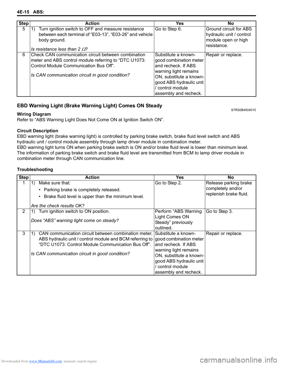
EBD Warning Light (Brake Warning Light) Comes ON SteadyS7RS0B4504010
Wiring Diagram
Refer to “ABS Warning Light Does Not Come ON at Ignition Switch ON”.
Circuit Description
EBD warning light (brake warn ing light) is controlled by parking brake switch, brake fluid level switch and ABS
hydraulic unit / control module assembly throug h lamp driver module in combination meter.
EBD warning light turns ON when parki ng brake switch is ON and/or brake fluid level is lower than minimum level.
The information of parking brake switch and brake fluid leve l are transmitted from BCM to lamp driver module in
combination meter through CAN communication line.
Troubleshooting 5 1) Turn ignition switch to OFF and measure resistance
between each terminal of “E03-13”, “E03-26” and vehicle
body ground.
Is resistance less than 2
Ω? Go to Step 6. Ground circuit for ABS
hydraulic unit / control
module open or high
resistance.
6 Check CAN communication circuit between combination meter and ABS control module referring to “DTC U1073:
Control Module Communication Bus Off”.
Is CAN communication circuit in good condition? Substitute a known-
good combination meter
and recheck. If ABS
warning light remains
ON, substitute a known-
good ABS hydraulic unit
/ control module
assembly and recheck.Repair or replace.
Step Action Yes No
Step
Action YesNo
1 1) Make sure that:
• Parking brake is completely released.
• Brake fluid level is upper than the minimum level.
Are the check results OK? Go to Step 2.
Release parking brake
completely and/or
replenish brake fluid.
2 1) Turn ignition switch to ON position. Does “ABS” warning light come on steady? Perform “ABS Warning
Light Comes ON
Steady” previously
outlined.Go to Step 3.
3 1) CAN communication circuit between combination meter, ABS hydraulic unit / control module and BCM referring to
“DTC U1073: Control Module Communication Bus Off”.
Is CAN communication circuit in good condition? Substitute a known-
good combination meter
and recheck. If ABS
warning light remains
ON, substitute a known-
good ABS hydraulic unit
/ control module
assembly and recheck.Repair or replace.
Page 576 of 1496
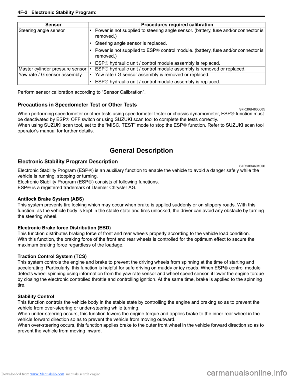
Downloaded from www.Manualslib.com manuals search engine 4F-2 Electronic Stability Program:
Perform sensor calibration according to “Sensor Calibration”.
Precautions in Speedometer Test or Other TestsS7RS0B4600005
When performing speedometer or other tests using speedometer tester or chassis dynamometer, ESP® function must
be deactivated by ESP ® OFF switch or using SUZUKI scan to ol to complete the tests correctly.
When using SUZUKI scan tool, set to the “MISC. TEST” mode to stop the ESP ® function. Refer to SUZUKI scan tool
operator's manual for further details.
General Description
Electronic Stability Program DescriptionS7RS0B4601006
Electronic Stability Program (ESP ®) is an auxiliary function to enable the vehicle to av oid a danger safely while the
vehicle is running, stopping or turning.
Electronic Stability Program (ESP ®) consists of following functions.
ESP ® is a registered trademark of Daimler Chrysler AG.
Antilock Brake System (ABS)
This system prevents tire locking which may occur when br ake is applied suddenly or on slippery roads. With this
function, as the vehicle body is kept in the stable state an d tires unlocked, the driver can avoid any obstacle by turning
the steering wheel.
Electronic Brake force Distribution (EBD)
This function distributes braking force of front and rear wheels properly according to the vehicle load condition.
With this function, the braking force of the front and rear wheels is controlled for the optimum effect to secure the
maximum braking force regardless of the loadage.
Traction Control System (TCS)
This system controls the engine and brake to prevent the dr iving wheels from spinning at the time of starting and
accelerating. Particularly, this fu nction is helpful for safe driving on muddy or icy roads. When ESP ® control module
detects wheel spinning using information from the yaw rate sensor and wheel speed sensor, it lower the engine torque
by closing the electronic controlled thro ttle and controlling ignition. At the same time, brake is applied to the spinning
tire.
Stability Control
This function controls the vehicle body in the stable state by controlling the engine and braking so as to prevent the
vehicle from over-steering or under-steering while turning.
When under-steering occurs, this function lowers the engine torque and applies brake to the inner rear wheel in the
vehicle forward direction so as to pr event the vehicle from moving outward.
When over-steering occurs, this function applies brake to the outer front wheel in the vehicle forward direction so as to
prevent the vehicle from moving inward. Sensor Procedures required calibration
Steering angle sensor • Power is not su pplied to steering angle sensor. (battery, fuse and/or connector is
removed.)
• Steering angle sensor is replaced.
• Power is not supplied to ESP ® control module. (battery, fuse and/or connector is
removed.)
• ESP® hydraulic unit / control module assembly is replaced.
Master cylinder pressure sensor • ESP® hydraulic unit / control module assembly is removed or replaced.
Yaw rate / G sensor assembly • Yaw rate / G sensor assembly is removed or replaced.
• ESP® hydraulic unit / control module assembly is replaced.
Page 579 of 1496
Downloaded from www.Manualslib.com manuals search engine Electronic Stability Program: 4F-5
Yaw rate / G sensor
The yaw rate / G sensor consists of the yaw rate (angular velocity in the vehicle turning direction) sensor and right-left
G (acceleration in right-left direction) sensor and is mounted to the P/S controller B/K at the lower part of the center
console. It detects the angular velocity in the vehicle turn ing direction and movement in the right-left direction, and
then it sends that information to ESP ® control module.
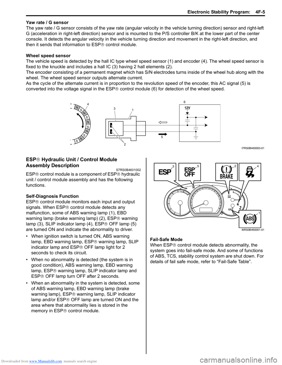
Wheel speed sensor
The vehicle speed is detected by the hall IC type wheel speed sensor (1) and encoder (4). The wheel speed sensor is
fixed to the knuckle and includes a hall IC (3) having 2 hall elements (2).
The encoder consisting of a permanent ma gnet which has S/N electrodes turns inside of the wheel hub along with the
wheel. The wheel speed sensor outputs alternate current.
As the cycle of the alternate current is in proportion to the revolution speed of the encoder, this AC signal (5) is
converted into the voltage signal in the ESP ® control module (6) for detection of the wheel speed.
ESP ® Hydraulic Unit / Control Module
Assembly Description
S7RS0B4601002
ESP ® control module is a component of ESP ® hydraulic
unit / control module assembly and has the following
functions.
Self-Diagnosis Function
ESP ® control module monitors each input and output
signals. When ESP ® control module detects any
malfunction, some of ABS warning lamp (1), EBD
warning lamp (brake warning lamp) (2), ESP ® warning
lamp (3), SLIP indicator lamp (4), ESP ® OFF lamp (5)
are turned ON and indicate the abnormality to driver.
• When ignition switch is turned ON, ABS warning lamp, EBD warning lamp, ESP ® warning lamp, SLIP
indicator lamp and ESP ® OFF lamp light for 2
seconds to check its circuit.
• When no abnormality is detected (the system is in good condition), ABS warning lamp, EBD warning
lamp, ESP ® warning lamp, SLIP indicator lamp and
ESP ® OFF lamp turn OFF after 2 seconds.
• When an abnormality in the system is detected, some of ABS warning lamp, EBD warning lamp (brake
warning lamp), ESP ® warning lamp, SLIP indicator
lamp and/or ESP ® OFF lamp are turned ON and the
area where that abnormality lies is stored in the
memory in ESP ® control module. Fail-Safe Mode
When ESP
® control module detects abnormality, the
system goes into fail-safe mode. And some of functions
of ABS, TCS, stability control system are shut down. For
details of fail safe mode, re fer to “Fail-Safe Table”.
S
N
S
N
S
N
N
S
N
S
12V
2
3
1
5
4
6I7RS0B460003-01
3245
1
I6RS0B460001-01
Page 594 of 1496
Downloaded from www.Manualslib.com manuals search engine 4F-20 Electronic Stability Program:
NOTE
•�{: Activated
• X: Deactivated
• *1: If two or more wheel speed sensor are defective, ABS warning lamp, EBD warning lamp and ESP ® warning lamp are lit and all the control functions are deactivated. If one wheel speed sensor is
defective, ABS warning lamp and ESP ® warning lamp are lit and ABS and TCS / stability control are
deactivated.
• *2: ESP ® OFF mode is cancelled and all control functions are activated.
• *3: EBD control function is activated only if po wer supply circuit is little low voltage malfunction.
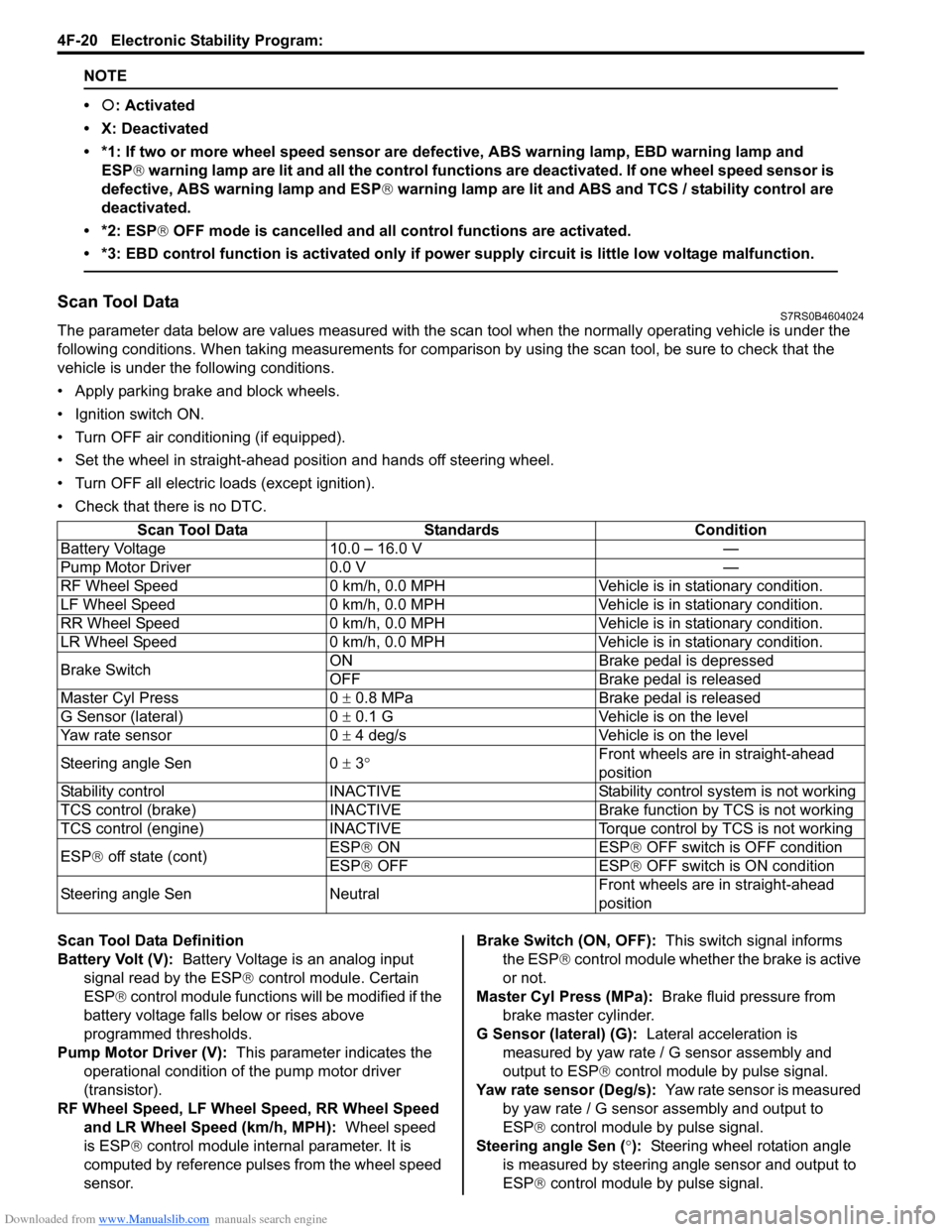
Scan Tool DataS7RS0B4604024
The parameter data below are values measured with the scan tool when the normally operating vehicle is under the
following conditions. When taking measurements for comparis on by using the scan tool, be sure to check that the
vehicle is under the following conditions.
• Apply parking brake and block wheels.
• Ignition switch ON.
• Turn OFF air conditioning (if equipped).
• Set the wheel in straight-ahead position and hands off steering wheel.
• Turn OFF all electric loads (except ignition).
• Check that there is no DTC.
Scan Tool Data Definition
Battery Volt (V): Battery Voltage is an analog input
signal read by the ESP ® control module. Certain
ESP ® control module functions will be modified if the
battery voltage falls below or rises above
programmed thresholds.
Pump Motor Driver (V): This parameter indicates the
operational condition of the pump motor driver
(transistor).
RF Wheel Speed, LF Wheel Speed, RR Wheel Speed and LR Wheel Speed (km/h, MPH): Wheel speed
is ESP ® control module internal parameter. It is
computed by reference puls es from the wheel speed
sensor. Brake Switch (ON, OFF):
This switch signal informs
the ESP ® control module whether the brake is active
or not.
Master Cyl Press (MPa): Brake fluid pressure from
brake master cylinder.
G Sensor (lateral) (G): Lateral acceleration is
measured by yaw rate / G sensor assembly and
output to ESP ® control module by pulse signal.
Yaw rate sensor (Deg/s): Yaw rate sensor is measured
by yaw rate / G sensor assembly and output to
ESP® control module by pulse signal.
Steering angle Sen ( °): Steering wheel rotation angle
is measured by steering angle sensor and output to
ESP® control module by pulse signal.
Scan Tool Data Standards Condition
Battery Voltage 10.0 – 16.0 V —
Pump Motor Driver 0.0 V —
RF Wheel Speed 0 km/h, 0.0 MPH Veh icle is in stationary condition.
LF Wheel Speed 0 km/h, 0.0 MPH Veh icle is in stationary condition.
RR Wheel Speed 0 km/h, 0.0 MPH Vehic le is in stationary condition.
LR Wheel Speed 0 km/h, 0.0 MPH Veh icle is in stationary condition.
Brake Switch ON Brake pedal is depressed
OFF Brake pedal is released
Master Cyl Press 0 ± 0.8 MPa Brake pedal is released
G Sensor (lateral) 0 ± 0.1 G Vehicle is on the level
Yaw rate sensor 0 ± 4 deg/s Vehicle is on the level
Steering angle Sen 0 ± 3 ° Front wheels are in straight-ahead
position
Stability control INACTIVE Stability control system is not working
TCS control (brake) INACTIVE Brake function by TCS is not working
TCS control (engine) INACTIVE Torque control by TCS is not working
ESP ® off state (cont) ESP®
ON ESP
® OF
F switch is OFF condition
ESP® OFF ESP ® OFF switch is ON condition
Steering angle Sen Neutral Front wheels are in straight-ahead
position
Page 599 of 1496
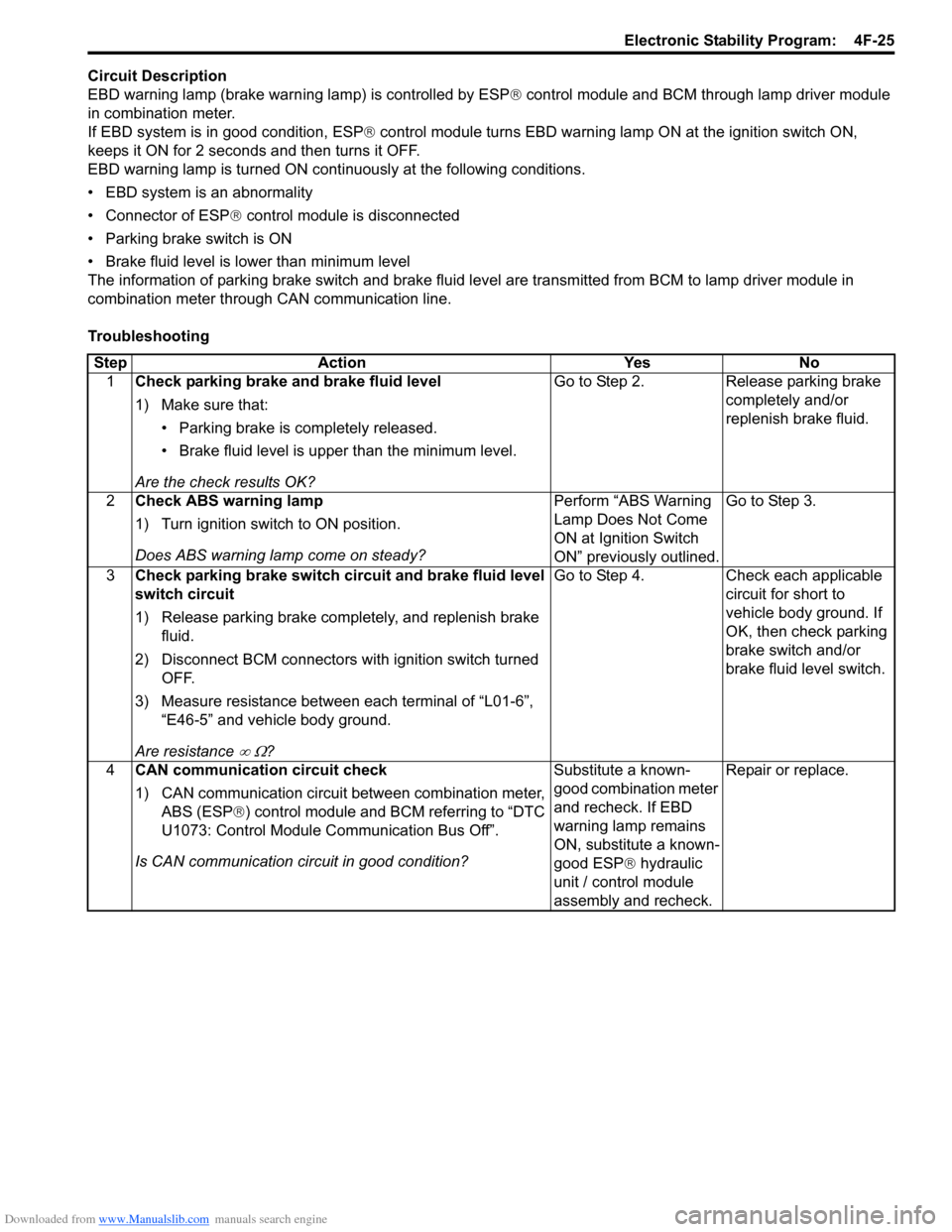
Downloaded from www.Manualslib.com manuals search engine Electronic Stability Program: 4F-25
Circuit Description
EBD warning lamp (brake warning lamp) is controlled by ESP® control module and BCM through lamp driver module
in combination meter.
If EBD system is in good condition, ESP ® control module turns EBD warning lamp ON at the ignition switch ON,
keeps it ON for 2 seconds and then turns it OFF.
EBD warning lamp is turned ON cont inuously at the following conditions.
• EBD system is an abnormality
• Connector of ESP ® control module is disconnected
• Parking brake switch is ON
• Brake fluid level is lower than minimum level
The information of parking brake switch and brake fluid leve l are transmitted from BCM to lamp driver module in
combination meter through CAN communication line.
Troubleshooting
Step Action Yes No 1 Check parking brake and brake fluid level
1) Make sure that:
• Parking brake is completely released.
• Brake fluid level is upper than the minimum level.
Are the check results OK? Go to Step 2. Release parking brake
completely and/or
replenish brake fluid.
2 Check ABS warning lamp
1) Turn ignition switch to ON position.
Does ABS warning lamp come on steady? Perform “ABS Warning
Lamp Does Not Come
ON at Ignition Switch
ON” previously outlined.Go to Step 3.
3 Check parking brake switch circuit and brake fluid level
switch circuit
1) Release parking brake completely, and replenish brake
fluid.
2) Disconnect BCM connectors with ignition switch turned OFF.
3) Measure resistance between each terminal of “L01-6”, “E46-5” and vehicle body ground.
Are resistance
∞ Ω? Go to Step 4. Check each applicable
circuit for short to
vehicle body ground. If
OK, then check parking
brake switch and/or
brake fluid level switch.
4 CAN communication circuit check
1) CAN communication circuit between combination meter,
ABS (ESP® ) control module and BCM referring to “DTC
U1073: Control Module Communication Bus Off”.
Is CAN communication circuit in good condition? Substitute a known-
good combination meter
and recheck. If EBD
warning lamp remains
ON, substitute a known-
good ESP
® hydraulic
unit / control module
assembly and recheck. Repair or replace.