App SUZUKI SWIFT 2005 2.G Service Workshop Manual
[x] Cancel search | Manufacturer: SUZUKI, Model Year: 2005, Model line: SWIFT, Model: SUZUKI SWIFT 2005 2.GPages: 1496, PDF Size: 34.44 MB
Page 1187 of 1496
Downloaded from www.Manualslib.com manuals search engine Wiring Systems: 9A-16
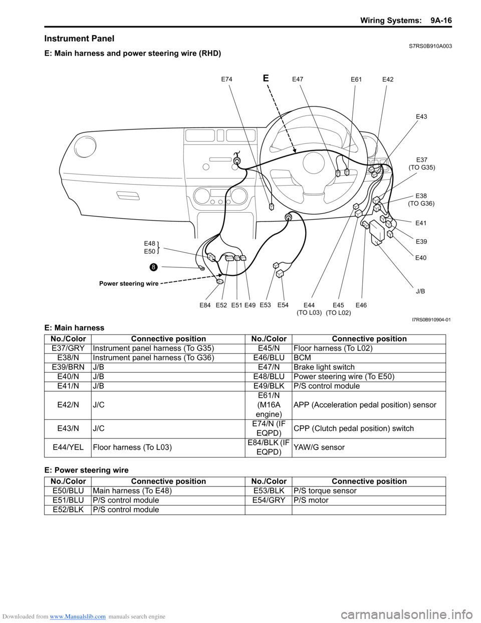
Instrument PanelS7RS0B910A003
E: Main harness and power steering wire (RHD)
E: Main harness
E: Power steering wire
J/B
E54
E53
E49
E51E52E84
E48
E50
Power steering wire
E47E74E42E61
E43
E45
(TO L02)
E44
(TO L03)E46
E40 E39
E41 E37
(TO G35)
E38
(TO G36)
8
E
I7RS0B910904-01
No./Color Connective position No./ColorConnective position
E37/GRY Instrument panel harness (To G35) E45/N Floor harness (To L02)
E38/N Instrument panel harness (To G36) E46/BLU BCM
E39/BRN J/B E47/N Brake light switch
E40/N J/B E48/BLU Power steering wire (To E50)
E41/N J/B E49/BLK P/S control module
E42/N J/C E61/N
(M16A
engine) APP (Acceleration pedal position) sensor
E43/N J/C E74/N (IF
EQPD) CPP (Clutch pedal position) switch
E44/YEL Floor harness (To L03) E84/BLK (IF
EQPD) YAW/G sensor
No./Color Connective position No./ColorConnective position
E50/BLU Main harness (To E48) E53/BLK P/S torque sensor
E51/BLU P/S control module E54/GRY P/S motor
E52/BLK P/S control module
Page 1224 of 1496
Downloaded from www.Manualslib.com manuals search engine 9A-53 Wiring Systems:
J/C
E43
J/C
G16
DLC
G20
G375
E469
E38
G3614
C36 E2415
BLK/ORN
BLK/ORN
BLK/ORN
4
BLK
11
J/C
G15
5
4
516
WHT/RED
C37
GRN/YELGRN/WHT
5 6
YG
BRN
B
P/S
Cont.M
4
"F-3"
25
A
A D
E
AA
PPL/WHT
PPL/WHT
PPL/WHT
PPL/WHT
YEL/GRNWHT/RED
BLK
9
A
PPL
E42
PPLJ/C
ECM
E394
J/B15A RADIO
40
E23
E23
YEL/BLKYEL/REDRED/BLU
13
282620
BLK
2C37
M/T
A/T
48
W
WHT
30
GYGW
BRN/WHTBLU/YEL
28
8
BWBY
IG COIL
#1 Generator
IG COIL
#2
(CAN) "A-3""A-2"
Audio
"G-1"
GRN/WHT
P
7
BCM
Starting motor relay
"A-1"
Transaxle
range sensor
YG"A-1"
ICM
"A-7"
P/S
Cont.M
"F-3"YBYRRBGW"D-7"
Brake light switch
"A-1"Starting motor
PW
PW
G335
WHT/BLKRED/BLK
RBWB
"A-8"
14
6
BCM
A
J/C
E43
APPL
P
E42C
IF EQPD IF EQPD
IF EQPD
I6RS0C910913-03
Page 1225 of 1496
Downloaded from www.Manualslib.com manuals search engine Wiring Systems: 9A-54
BLU
12
Diagnosis
connector #1
E572
ECM
GRN
Relay #2Relay #3
G
"A-4"
E2348
RHD
WHT
BCM
APP sensor
Electric throttle body
Throttle position sensor
SUB
open
close
open
close
open
close
open
close
MAIN
SUB
MAIN
Throttle
actuator
REDBRNGRNBLUREDYELWHTBLKWHTGRNREDLT GRN/REDLT GRN/BLK
E46
3 18
TCM
WHTRED
7 17
C37
C34
1 2
ABS
Cont.MESP
Cont.M
E0310 8
or
E612
3C421 256431564
12 13
RW
5041424054434445513634523735E23
C37
A/T
BLK
31
22
(CAN) (CAN)
M13A engine, M15A engine
M16A engine
AB
B
RB
B
A
I7RS0B910914-01
Page 1288 of 1496
Downloaded from www.Manualslib.com manuals search engine 9B-6 Lighting Systems:
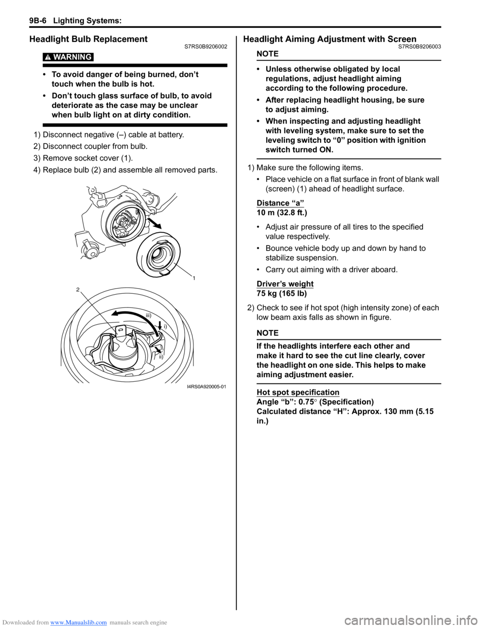
Headlight Bulb ReplacementS7RS0B9206002
WARNING!
• To avoid danger of being burned, don’t touch when the bulb is hot.
• Don’t touch glass surface of bulb, to avoid deteriorate as the case may be unclear
when bulb light on at dirty condition.
1) Disconnect negative (–) cable at battery.
2) Disconnect coupler from bulb.
3) Remove socket cover (1).
4) Replace bulb (2) and assemble all removed parts.
Headlight Aiming Adjustment with ScreenS7RS0B9206003
NOTE
• Unless otherwise obligated by local regulations, adjust headlight aiming
according to the following procedure.
• After replacing headlight housing, be sure to adjust aiming.
• When inspecting and adjusting headlight with leveling system, make sure to set the
leveling switch to “0 ” position with ignition
switch turned ON.
1) Make sure the following items.
• Place vehicle on a flat surface in front of blank wall (screen) (1) ahead of headlight surface.
Distance “a”
10 m (32.8 ft.)
• Adjust air pressure of all tires to the specified value respectively.
• Bounce vehicle body up and down by hand to stabilize suspension.
• Carry out aiming with a driver aboard.
Driver’s weight
75 kg (165 lb)
2) Check to see if hot spot (high intensity zone) of each low beam axis falls as shown in figure.
NOTE
If the headlights interfere each other and
make it hard to see the cut line clearly, cover
the headlight on one side. This helps to make
aiming adjustment easier.
Hot spot specification
Angle “b”: 0.75 ° (Specification)
Calculated distance “H”: Approx. 130 mm (5.15
in.)
1
iii)
2
i)
ii)
I4RS0A920005-01
Page 1294 of 1496
Downloaded from www.Manualslib.com manuals search engine 9B-12 Lighting Systems:
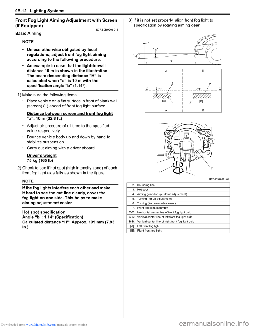
Front Fog Light Aiming Adjustment with Screen
(If Equipped)
S7RS0B9206018
Basic Aiming
NOTE
• Unless otherwise obligated by local regulations, adjust front fog light aiming
according to the following procedure.
• An example in case that the light-to-wall distance 10 m is shown in the illustration.
The beam descending distance “H” is
calculated when “a” is 10 m with the
specification angle “b” (1.14 °).
1) Make sure the following items.
• Place vehicle on a flat surface in front of blank wall (screen) (1) ahead of front fog light surface.
Distance between screen and front fog light
“a”: 10 m (32.8 ft.)
• Adjust air pressure of all tires to the specified value respectively.
• Bounce vehicle body up and down by hand to stabilize suspension.
• Carry out aiming with a driver aboard.
Driver’s weight
75 kg (165 lb)
2) Check to see if hot spot (h igh intensity zone) of each
front fog light axis falls as shown in the figure.
NOTE
If the fog lights interfere each other and make
it hard to see the cut line clearly, cover the
fog light on one side. This helps to make
aiming adjustment easier.
Hot spot specification
Angle “b”: 1.14° (Specification)
Calculated distance “H”: Approx. 199 mm (7.83
in.) 3) If it is not set properly
, align front fog light to
specification by rotating aiming gear.
2. Bounding line
3. Hot spot
4. Aiming gear (for up / down adjustment)
5. Turning (for up adjustment)
6. Turning (for down adjustment)
7. Front fog light assembly
X-X: Horizontal center line of front fog light bulb
A-A: Vertical center line of left front fog light bulb
B-B: Vertical center line of right front fog light bulb [A]: Left front fog light
[B]: Right front fog light
I4RS0B920011-01
Page 1302 of 1496
Downloaded from www.Manualslib.com manuals search engine 9C-7 Instrumentation / Driver Info. / Horn:
Engine Coolant Temperature (ECT) Meter Symptom DiagnosisS7RS0B9304003
Fuel Meter Symptom DiagnosisS7RS0B9304004
Low Fuel Warning Light Symptom DiagnosisS7RS0B9304005
NOTE
Confirm that fuel meter is in good condition before referring to the following possible causes.
• When fuel level sensor circuit is open or short, fuel meter indicates empty even if fuel tank does not empty.
• The low fuel warning light comes ON when fu el level is lower than specification below.
Low fuel warning light operation:
ConditionPossible cause Correction / Reference Item
Engine coolant
temperature (ECT) meter
shows no operation or
incorrect operation Circuit fuse blown
Replace fuse and check for short circuit.
ECT sensor faulty Check ECT sensor referring to “ECT Sensor
Inspection in Section 1C”.
Wiring and/or grounding faulty Repair as necessary.
Combination meter faulty Replace combination meter.
ECM faulty Replace after making sure that none of above
parts is faulty.
ConditionPossible cause Correction / Reference Item
Fuel meter shows no
operation or incorrect
operation Circuit fuse blown
Replace fuse and check for short circuit.
Fuel level sensor faulty Check fuel level sensor referring to “Fuel Level
Sensor Inspection”.
Wiring and/or grounding faulty Repair as necessary.
Combination meter faulty Replace combination meter.
Low fuel warning light operation: Fuel amount: Resistance of fuel level sensor:
ON Approx. 6.5 liter Approx. 251 Ω
Condition Possible cause Correction / Reference Item
Low fuel warning light
does not come ON when
fuel level is lower than
specification Circuit fuse blown
Replace fuse and check for short circuit.
Fuel level sensor faulty Check fuel level sensor referring to “Fuel Level
Sensor Inspection”.
Wiring and/or grounding faulty Repair as necessary.
Combination meter faulty Replace combination meter.
Low fuel warning light
comes ON steady Low fuel
Refill fuel.
Fuel level sensor faulty Check fuel level sensor referring to “Fuel Level
Sensor Inspection”.
Wiring and/or grounding faulty Repair as necessary.
Combination meter faulty Replace combination meter.
Page 1326 of 1496
Downloaded from www.Manualslib.com manuals search engine 9D-9 Wipers / Washers:
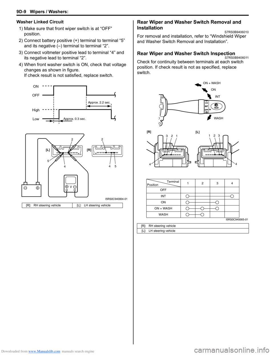
Washer Linked Circuit1) Make sure that front wiper switch is at “OFF” position.
2) Connect battery positive (+ ) terminal to terminal “5”
and its negative (–) terminal to terminal “2”.
3) Connect voltmeter positive lead to terminal “4” and its negative lead to terminal “2”.
4) When front washer switch is ON, check that voltage
changes as shown in figure.
If check result is not satisfied, replace switch.Rear Wiper and Washer Switch Removal and
Installation
S7RS0B9406010
For removal and installation, refer to “Windshield Wiper
and Washer Switch Removal and Installation”.
Rear Wiper and Washer Switch InspectionS7RS0B9406011
Check for continuity between terminals at each switch
position. If check result is not as specified, replace
switch.
[R]: RH steering vehicle [L]: LH steering vehicle
V
2
4
52
45
[L] [R]
ON
OFF
High Low
Approx. 0.3 sec. Approx. 2.2 sec.
I5RS0C940004-01
[R]: RH steering vehicle
[L]: LH steering vehicle
Terminal
Position
OFF
INT 4
3
12
WASH ON
ON + WASH
ON + WASH
INT
ON
WASH
123
4
[R]
[L]123
4
I5RS0C940005-01
Page 1329 of 1496
Downloaded from www.Manualslib.com manuals search engine Glass / Windows / Mirrors: 9E-2
• Eyeleteer
• Piano string
• Windshield knife
• Brush for primer application (2 pcs)
•Knife
• Rubber sucker grip
• Sealant gun (for filling adhesive)
• Putty spatula (for correcting adhered parts)
Diagnostic Information and Procedures
Rear End door Window Defogger Symptom DiagnosisS7RS0B9504001
NOTE
• Use of SUZUKI scan tool makes it easy to check whether a faulty condition is on the input side or
output side of BCM. For checking procedure, re fer to “Diagnosis Using Output Test Function of
SUZUKI Scan Tool” under “Scan Tool Data in Section 10B”.
• Check each part in the order from the top of the following list.
Power Window Control System Symptom DiagnosisS7RS0B9504002
Condition Possible cause Correction / Reference Item
Rear end door window
defogger does not
operate Circuit fuse blown
Replace fuse and check for short circuit.
Rear end door window defogger switch
faulty Check rear end door window defogger switch
referring to “Rear End Door Window Defogger
Switch Inspection”.
Rear end door window defogger relay
faulty Check rear end door window defogger relay
referring to “Rear End Door Window Defogger
Relay Inspection”.
Defogger wire faulty Check defogger wire referring to “Rear End
Door Window Defogger Wire Inspection”.
Wiring or grounding faulty Repair circuit.
BCM faulty Replace after making sure that none of above
parts is faulty.
ConditionPossible cause Correction / Reference Item
All power windows do not
operate Circuit fuse blown
Replace fuse and check for short circuit.
Power window main switch faulty Check power window main switch referring to
“Power Window Main Switch Inspection”.
Ignition switch faulty Check ignition switch referring to “Ignition
Switch Inspection in Section 9C”.
Wiring or grounding faulty Repair circuit.
Only one power window
does not operate Power window main switch faulty
Check power window main switch referring to
“Power Window Main Switch Inspection”.
Power window sub switch faulty Check power window sub switch referring to
“Power Window Sub Switch Inspection”.
Wiring and/or coupler faulty Check wiring and/or coupler.
Power window regulator faulty Check window regulator.
Power window motor faulty Check power window motor.
Wiring or grounding faulty Repair circuit.
Page 1332 of 1496
Downloaded from www.Manualslib.com manuals search engine 9E-5 Glass / Windows / Mirrors:
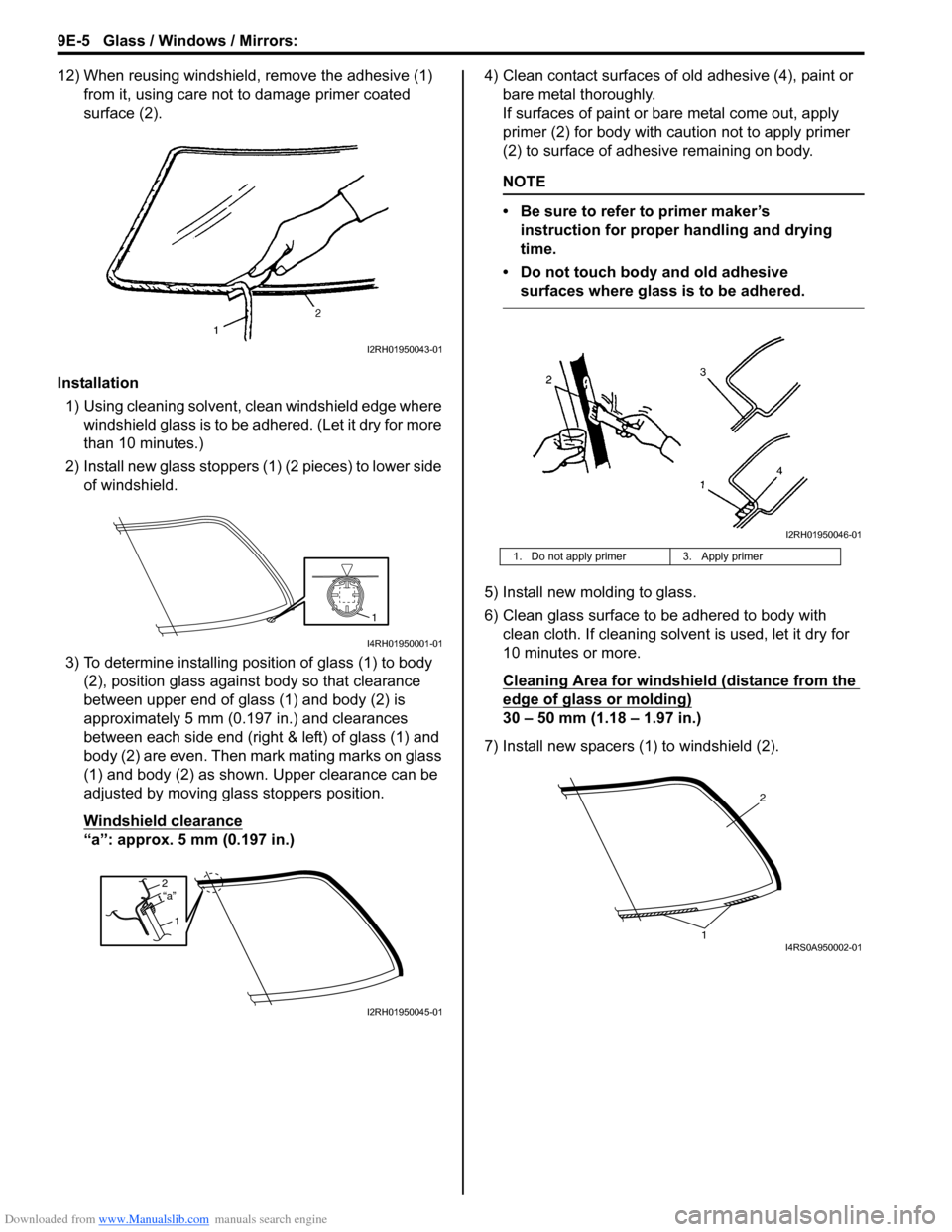
12) When reusing windshield, remove the adhesive (1) from it, using care not to damage primer coated
surface (2).
Installation 1) Using cleaning solvent, clean windshield edge where windshield glass is to be adhered. (Let it dry for more
than 10 minutes.)
2) Install new glass stoppers (1) (2 pieces) to lower side of windshield.
3) To determine installing position of glass (1) to body (2), position glass against body so that clearance
between upper end of glass (1) and body (2) is
approximately 5 mm (0.197 in.) and clearances
between each side end (right & left) of glass (1) and
body (2) are even. Then mark mating marks on glass
(1) and body (2) as shown. Upper clearance can be
adjusted by moving glass stoppers position.
Windshield clearance
“a”: approx. 5 mm (0.197 in.) 4) Clean contact surfaces of old adhesive (4), paint or
bare metal thoroughly.
If surfaces of paint or ba re metal come out, apply
primer (2) for body with caution not to apply primer
(2) to surface of adhesive remaining on body.
NOTE
• Be sure to refer to primer maker’s instruction for proper handling and drying
time.
• Do not touch body and old adhesive surfaces where glass is to be adhered.
5) Install new molding to glass.
6) Clean glass surface to be adhered to body with clean cloth. If cleaning solvent is used, let it dry for
10 minutes or more.
Cleaning Area for windshie ld (distance from the
edge of glass or molding)
30 – 50 mm (1.18 – 1.97 in.)
7) Install new spacers (1) to windshield (2).
I2RH01950043-01
1
I4RH01950001-01
2
1“a”
I2RH01950045-01
1. Do not apply primer 3. Apply primer
I2RH01950046-01
2
1I4RS0A950002-01
Page 1333 of 1496
Downloaded from www.Manualslib.com manuals search engine Glass / Windows / Mirrors: 9E-6
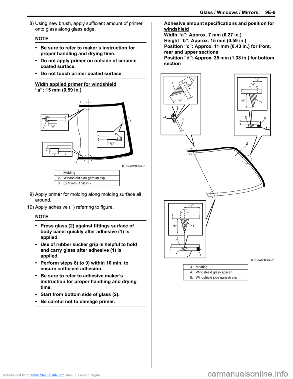
8) Using new brush, apply sufficient amount of primer onto glass along glass edge.
NOTE
• Be sure to refer to maker’s instruction for
proper handling and drying time.
• Do not apply primer on outside of ceramic coated surface.
• Do not touch primer coated surface.
Width applied primer for windshield
“a”: 15 mm (0.59 in.)
9) Apply primer for molding along molding surface all around.
10) Apply adhesive (1) referring to figure.
NOTE
• Press glass (2) against fittings surface of body panel quickly after adhesive (1) is
applied.
• Use of rubber sucker gr ip is helpful to hold
and carry glass after adhesive (1) is
applied.
• Perform steps 8) to 9) within 10 min. to ensure sufficient adhesion.
• Be sure to refer to adhesive maker’s instruction for proper handling and drying
time.
• Start from bottom side of glass (2).
• Be careful not to damage primer.
Adhesive amount specifications and position for
windshield
Width “a”: Approx. 7 mm (0.27 in.)
Height “b”: Approx. 15 mm (0.59 in.)
Position “c”: Approx. 11 mm (0.43 in.) for front,
rear and upper sections
Position “d”: Approx. 35 mm (1.38 in.) for bottom
section
1. Molding
2. Windshield side garnish clip
3. 32.5 mm (1.28 in.)
“a”
1
“a”
“a”
2
3
I4RS0A950003-01
3. Molding
4. Windshield glass spacer
5. Windshield side garnish clip
2
2
4
1
“b” “d”
“b”
“c”
2
1
“a”
3
2
1
“b”
“c”
5
“a”
“a”
I4RS0A950004-01