headlight SUZUKI SWIFT 2005 2.G Service Owner's Guide
[x] Cancel search | Manufacturer: SUZUKI, Model Year: 2005, Model line: SWIFT, Model: SUZUKI SWIFT 2005 2.GPages: 1496, PDF Size: 34.44 MB
Page 1371 of 1496

Downloaded from www.Manualslib.com manuals search engine Hood / Fenders / Doors: 9J-2
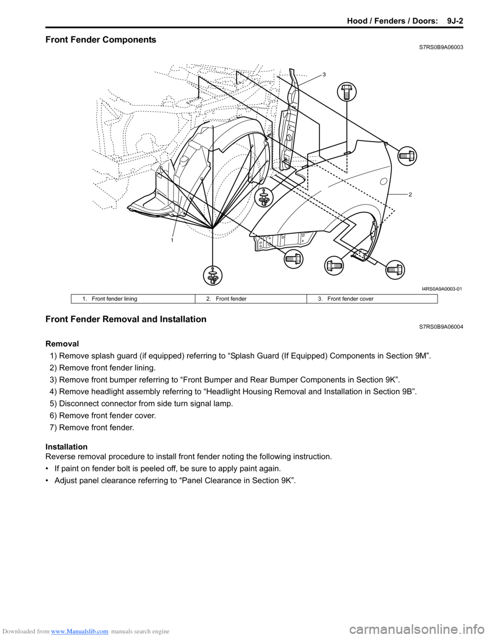
Front Fender ComponentsS7RS0B9A06003
Front Fender Removal and InstallationS7RS0B9A06004
Removal1) Remove splash guard (if equipped) referring to “Splash Guard (If Equipped) Components in Section 9M”.
2) Remove front fender lining.
3) Remove front bumper referring to “Front Bumper and Rear Bumper Components in Section 9K”.
4) Remove headlight assembly referring to “Headlig ht Housing Removal and Installation in Section 9B”.
5) Disconnect connector from side turn signal lamp.
6) Remove front fender cover.
7) Remove front fender.
Installation
Reverse removal procedure to install fron t fender noting the following instruction.
• If paint on fender bolt is peeled off, be sure to apply paint again.
• Adjust panel clearance referring to “Panel Clearance in Section 9K”.
1 2
3
I4RS0A9A0003-01
1. Front fender lining
2. Front fender3. Front fender cover
Page 1380 of 1496

Downloaded from www.Manualslib.com manuals search engine 9K-3 Body Structure:
Specifications
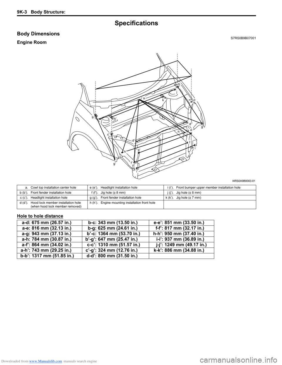
Body DimensionsS7RS0B9B07001
Engine Room
Hole to hole distance
g’
b
ckg
i
a
b’
c’
d
d’
e
e’
f’
f
h
h’
i’ j
k’
j’
I4RS0A9B0003-01
a. Cowl top installation center hole e (e’). Headlight installation hole i (i’). Front bumper upper member installation hole
b (b’). Front fender installation hole f (f’). Jig hole (φ 8 mm) j (j’). Jig hole (φ 8 mm)
c (c’). Headlight installation hole g (g’). Front fender installation hole k (k’). Jig hole (φ 7 mm)
d (d’). Hood lock member installation hole (when hood lock member removed) h (h’). Engine mounting installation front hole
a-d: 675 mm (26.57 in.) b-c: 343 mm (13.50 in.) e-e’: 851 mm (33.50 in.)
a-e: 816 mm (32.13 in.) b-g: 625 mm (24.61 in.) f-f’: 817 mm (32.17 in.)
a-g: 943 mm (37.13 in.) b’-c: 1364 mm (53.70 in.) h-h’: 950 mm (37.40 in.)
a-h: 784 mm (30.87 in.) b’-g’: 647 mm (25.47 in.) i-i’: 937 mm (36.89 in.)
a-f’: 864 mm (34.02 in.) c-c’: 1310 mm (51.57 in.) j-j’: 1249 mm (49.17 in.)
a-h’: 743 mm (29.25 in.) c’-g’: 324 mm (12.76 in.) k-k’: 886 mm (34.88 in.)
b-b’: 1317 mm (51.85 in.) d-d’: 800 mm (31.50 in.)
Page 1418 of 1496

Downloaded from www.Manualslib.com manuals search engine 10B-15 Body Electrical Control System:
Without Using SUZUKI Scan Tool1) Turn ignition switch to OFF position.
2) Perform following Steps a) to d) within 10 seconds af ter ignition switch is turned ON and engine stops.
a) Turn headlight switch to “SMALL” position.
b) Turn headlight switch to “OFF” position.
c) Repeat Steps a) and b) 2 times.
d) Press and release driver side door switch 3 times.
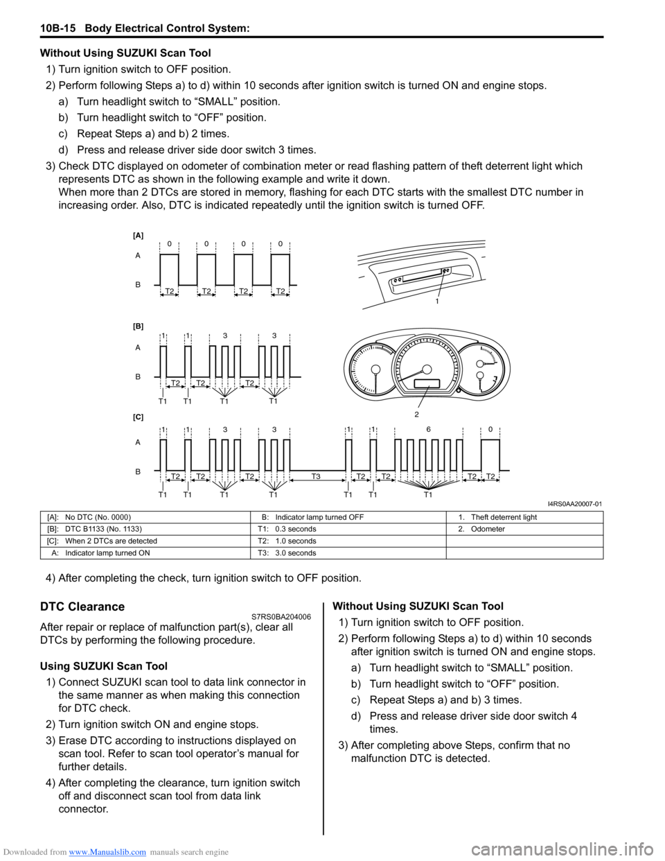
3) Check DTC displayed on odometer of combination meter or read flashing pattern of theft deterrent light which
represents DTC as shown in the following example and write it down.
When more than 2 DTCs are stored in memory, flashing for each DTC starts with the smallest DTC number in
increasing order. Also, DTC is indicated repeatedly until the ignition switch is turned OFF.
4) After completing the check, turn ignition switch to OFF position.
DTC ClearanceS7RS0BA204006
After repair or replace of malfunction part(s), clear all
DTCs by performing the following procedure.
Using SUZUKI Scan Tool 1) Connect SUZUKI scan tool to data link connector in the same manner as when making this connection
for DTC check.
2) Turn ignition switch ON and engine stops.
3) Erase DTC according to instructions displayed on scan tool. Refer to scan tool operator’s manual for
further details.
4) After completing the clear ance, turn ignition switch
off and disconnect scan tool from data link
connector. Without Using SUZUKI Scan Tool
1) Turn ignition switch to OFF position.
2) Perform following Steps a) to d) within 10 seconds after ignition switch is turned ON and engine stops.
a) Turn headlight switch to “SMALL” position.
b) Turn headlight switch to “OFF” position.
c) Repeat Steps a) and b) 3 times.
d) Press and release driver side door switch 4 times.
3) After completing above Steps, confirm that no malfunction DTC is detected.
B A
[B] [A]
[C]
B A B A
3
113
3
113
T2
T1 T1 T1 T1
1
2
T2T2
T2
T1 T1 T1 T1T2T2
0
T2
0
T2
0
T2
0
T2
11 6 0
T1 T1 T1
T2
T3T2T2T2
I4RS0AA20007-01
[A]: No DTC (No. 0000) B: Indicator lamp turned OFF1. Theft deterrent light
[B]: DTC B1133 (No. 1133) T1: 0.3 seconds2. Odometer
[C]: When 2 DTCs are detected T2: 1.0 seconds
A: Indicator lamp tur ned ON T3: 3.0 seconds