Can SUZUKI SWIFT 2005 2.G Service Workshop Manual
[x] Cancel search | Manufacturer: SUZUKI, Model Year: 2005, Model line: SWIFT, Model: SUZUKI SWIFT 2005 2.GPages: 1496, PDF Size: 34.44 MB
Page 1296 of 1496
Downloaded from www.Manualslib.com manuals search engine 9C-1 Instrumentation / Driver Info. / Horn:
Body, Cab and Accessories
Instrumentation / Driver Info. / Horn
Precautions
Precautions in Diagnosing Troubles for Combination MeterS7RS0B9300001
Combination meter uses signals (information) from each control module by CAN communication to control
speedometer, tachometer, engine coolant temp meter, warning light and indicator light (other than air bag warning
light, high beam indicator light, EPS warn ing light and turn signal indicator light). Therefore, check that no DTC is
detected in each module before performing combination me ter symptom diagnosis. If any DTC is detected, correct
trouble indicated by that DTC troubleshooting first.
General Description
CAN Communication System DescriptionS7RS0B9301001
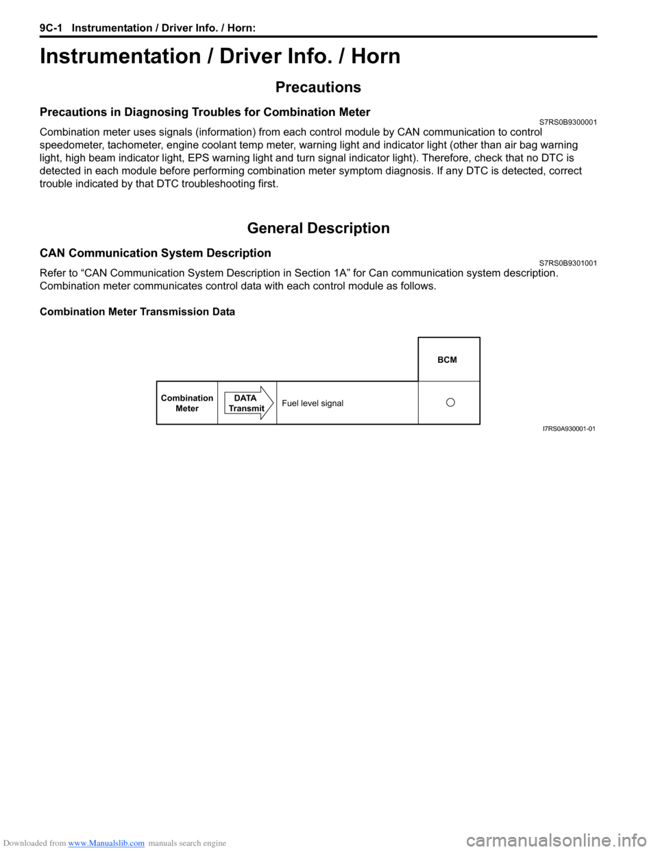
Refer to “CAN Communication System Description in Section 1A” for Can communication system description.
Combination meter communicates control data with each control module as follows.
Combination Meter Transmission Data
BCM
Combination Meter DATA
TransmitFuel level signal
I7RS0A930001-01
Page 1299 of 1496
Downloaded from www.Manualslib.com manuals search engine Instrumentation / Driver Info. / Horn: 9C-4
Schematic and Routing Diagram
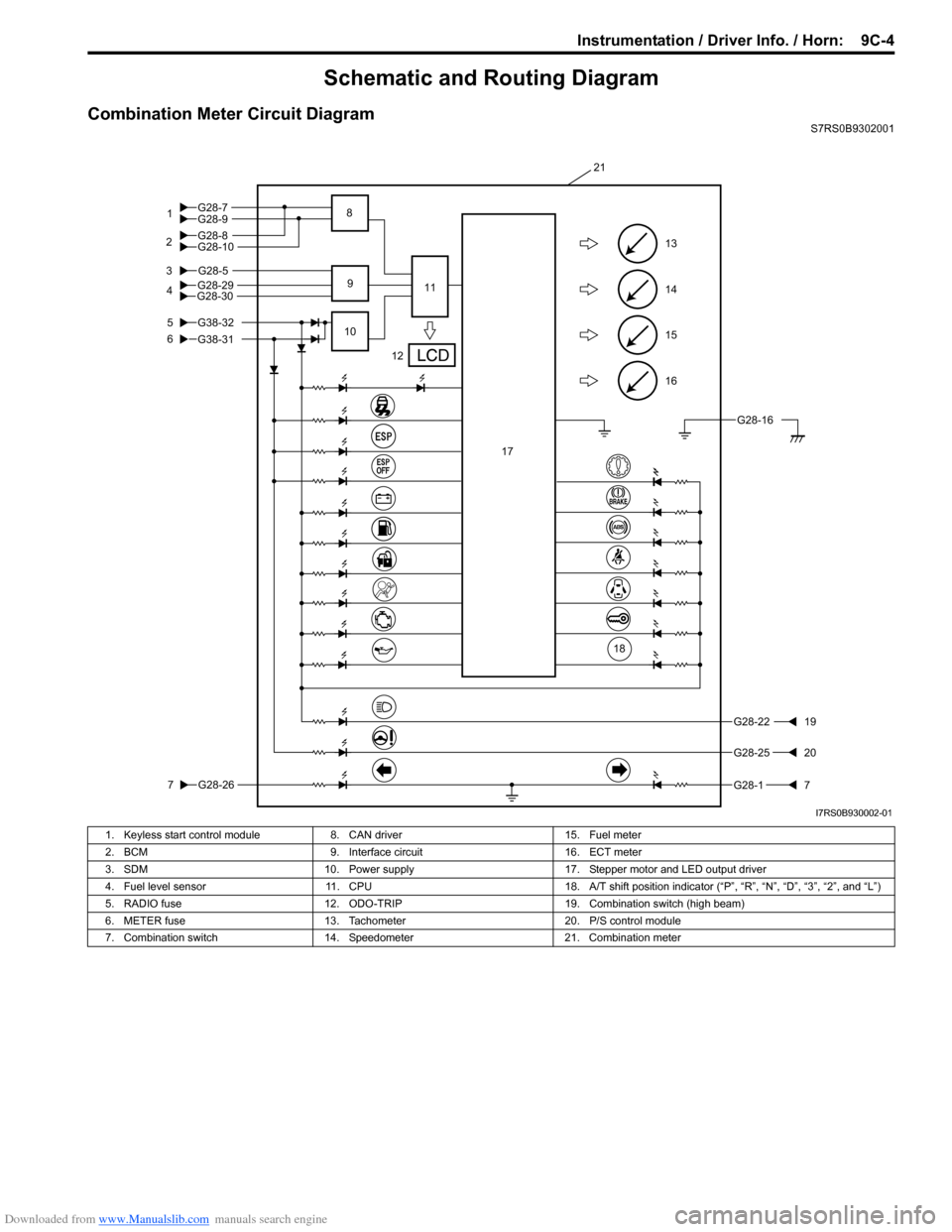
Combination Meter Circuit DiagramS7RS0B9302001
16
15
14
13
G28-5
5
6
3
G28-26
7
G28-2219
G28-2520
G28-17
12
10 11
21
9
17
G28-304G28-29
18
G28-16
G28-9
G28-10G28-8 G28-7
1
2 8
G38-31
G38-32
I7RS0B930002-01
1. Keyless start control module
8. CAN driver 15. Fuel meter
2. BCM 9. Interface circuit 16. ECT meter
3. SDM 10. Power supply 17. Stepper motor and LED output driver
4. Fuel level sensor 11. CPU 18. A/T shift position indicator (“P”, “R”, “N”, “D”, “3”, “2”, and “L”)
5. RADIO fuse 12. ODO-TRIP 19. Combination switch (high beam)
6. METER fuse 13. Tachometer 20. P/S control module
7. Combination switch 14. Speedometer 21. Combination meter
Page 1300 of 1496
Downloaded from www.Manualslib.com manuals search engine 9C-5 Instrumentation / Driver Info. / Horn:
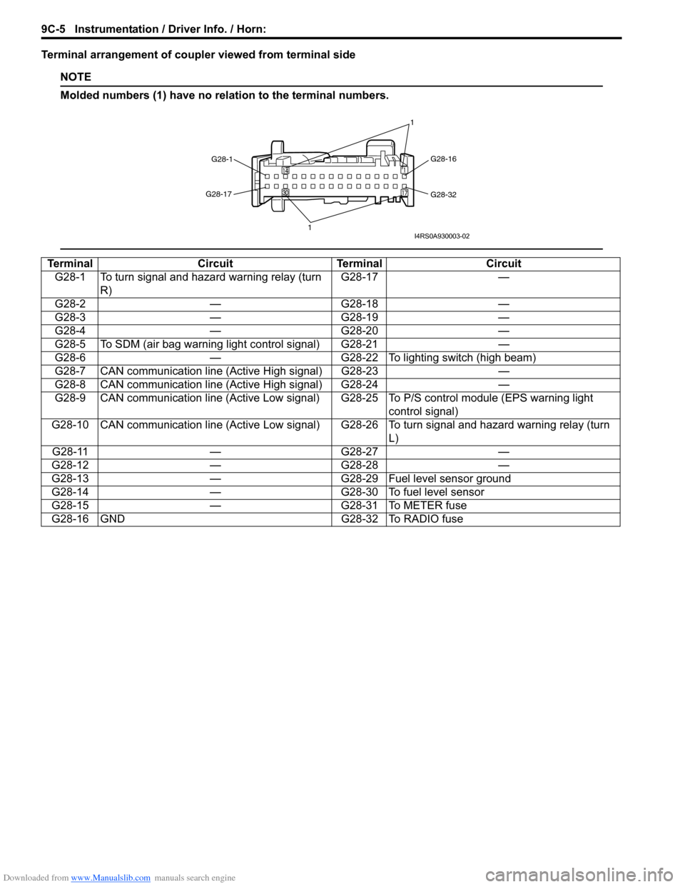
Terminal arrangement of coupler viewed from terminal side
NOTE
Molded numbers (1) have no relation to the terminal numbers.
TerminalCircuitTerminal Circuit
G28-1 To turn signal and hazard warning relay (turn R) G28-17
—
G28-2 —G28-18 —
G28-3 —G28-19 —
G28-4 —G28-20 —
G28-5 To SDM (air bag warning light control signal) G28-21 —
G28-6 —G28-22 To lighting switch (high beam)
G28-7 CAN communication line (Active High signal) G28-23 —
G28-8 CAN communication line (Active High signal) G28-24 —
G28-9 CAN communication line (Active Low signal) G 28-25 To P/S control module (EPS warning light
control signal)
G28-10 CAN communication line (Active Low signal) G28-26 To turn signal and hazard warning relay (turn L)
G28-11 —G28-27 —
G28-12 —G28-28 —
G28-13 —G28-29 Fuel level sensor ground
G28-14 —G28-30 To fuel level sensor
G28-15 —G28-31 To METER fuse
G28-16 GND G28-32 To RADIO fuse
G28-1 G28-16
G28-32
G28-17
1 1I4RS0A930003-02
Page 1305 of 1496
Downloaded from www.Manualslib.com manuals search engine Instrumentation / Driver Info. / Horn: 9C-10
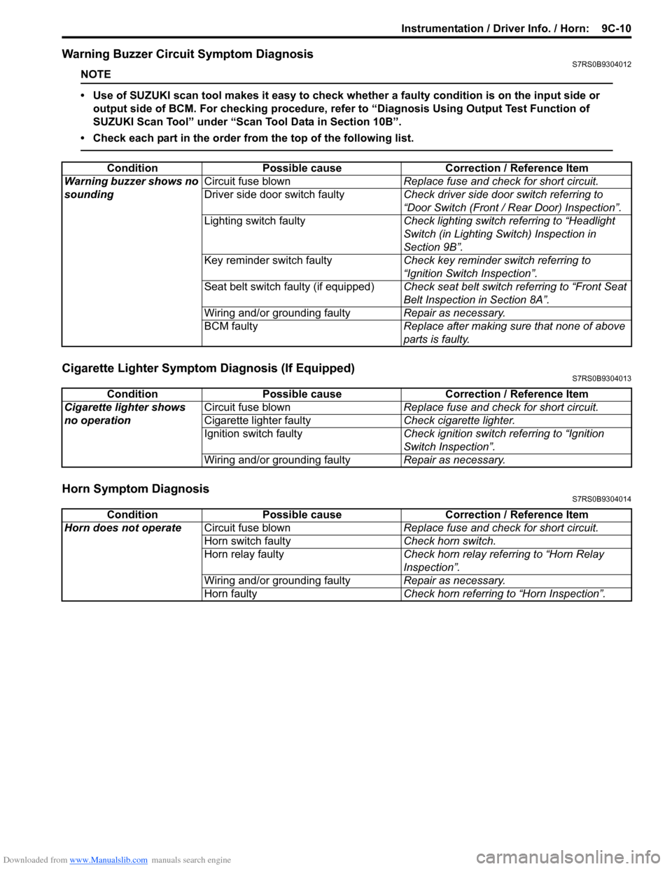
Warning Buzzer Circuit Symptom DiagnosisS7RS0B9304012
NOTE
• Use of SUZUKI scan tool makes it easy to check wh ether a faulty condition is on the input side or
output side of BCM. For checking procedure, re fer to “Diagnosis Using Output Test Function of
SUZUKI Scan Tool” under “Scan Tool Data in Section 10B”.
• Check each part in the order from the top of the following list.
Cigarette Lighter Symptom Diagnosis (If Equipped)S7RS0B9304013
Horn Symptom DiagnosisS7RS0B9304014
Condition Possible cause Correction / Reference Item
Warning buzzer shows no
sounding Circuit fuse blown
Replace fuse and check for short circuit.
Driver side door switch faulty Check driver side door switch referring to
“Door Switch (Front / Rear Door) Inspection”.
Lighting switch faulty Check lighting switch referring to “Headlight
Switch (in Lighting Switch) Inspection in
Section 9B”.
Key reminder switch faulty Check key reminder switch referring to
“Ignition Switch Inspection”.
Seat belt switch faulty (if equipped) Check seat belt switch referring to “Front Seat
Belt Inspection in Section 8A”.
Wiring and/or grounding faulty Repair as necessary.
BCM faulty Replace after making sure that none of above
parts is faulty.
ConditionPossible cause Correction / Reference Item
Cigarette lighter shows
no operation Circuit fuse blown
Replace fuse and check for short circuit.
Cigarette lighter faulty Check cigarette lighter.
Ignition switch faulty Check ignition switch referring to “Ignition
Switch Inspection”.
Wiring and/or grounding faulty Repair as necessary.
ConditionPossible cause Correction / Reference Item
Horn does not operate Circuit fuse blown Replace fuse and check for short circuit.
Horn switch faulty Check horn switch.
Horn relay faulty Check horn relay referring to “Horn Relay
Inspection”.
Wiring and/or grounding faulty Repair as necessary.
Horn faulty Check horn referring to “Horn Inspection”.
Page 1318 of 1496
Downloaded from www.Manualslib.com manuals search engine 9D-1 Wipers / Washers:
Body, Cab and Accessories
Wipers / Washers
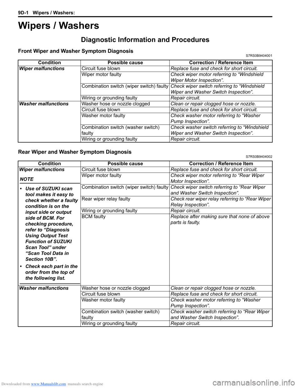
Diagnostic Information and Procedures
Front Wiper and Washer Symptom DiagnosisS7RS0B9404001
Rear Wiper and Washer Symptom DiagnosisS7RS0B9404002
ConditionPossible cause Correction / Reference Item
Wiper malfunctions Circuit fuse blown Replace fuse and check for short circuit.
Wiper motor faulty Check wiper motor referring to “Windshield
Wiper Motor Inspection”.
Combination switch (wiper switch) faulty Check wiper switch referring to “Windshield
Wiper and Washer Switch Inspection”.
Wiring or grounding faulty Repair circuit.
Washer malfunctions Washer hose or nozzle clogged Clean or repair clogged hose or nozzle.
Circuit fuse blown Replace fuse and check for short circuit.
Washer motor faulty Check washer motor referring to “Washer
Pump Inspection”.
Combination switch (washer switch)
faulty Check washer switch referring to “Windshield
Wiper and Washer Switch Inspection”.
Wiring or grounding faulty Repair circuit.
ConditionPossible cause Correction / Reference Item
Wiper malfunctions
NOTE
• Use of SUZUKI scan tool makes it easy to
check whether a faulty
condition is on the
input side or output
side of BCM. For
checking procedure,
refer to “Diagnosis
Using Output Test
Function of SUZUKI
Scan Tool” under
“Scan Tool Data in
Section 10B”.
• Check each part in the order from the top of
the following list.
Circuit fuse blown Replace fuse and check for short circuit.
Wiper motor faulty Check wiper motor referring to “Rear Wiper
Motor Inspection”.
Combination switch (wiper switch) faulty Check wiper switch referring to “Rear Wiper
and Washer Switch Inspection”.
Rear wiper relay faulty Check rear wiper relay referring to “Rear Wiper
Relay Inspection”.
Wiring or grounding faulty Repair circuit.
BCM faulty Replace after making sure that none of above
parts is faulty.
Washer malfunctions Washer hose or nozzle clogged Clean or repair clogged hose or nozzle.
Circuit fuse blown Replace fuse and check for short circuit.
Washer motor faulty Check washer motor referring to “Washer
Pump Inspection”.
Combination switch (washer switch)
faulty Check washer switch referring to “Rear Wiper
and Washer Switch Inspection”.
Wiring or grounding faulty Repair circuit.
Page 1320 of 1496
Downloaded from www.Manualslib.com manuals search engine 9D-3 Wipers / Washers:
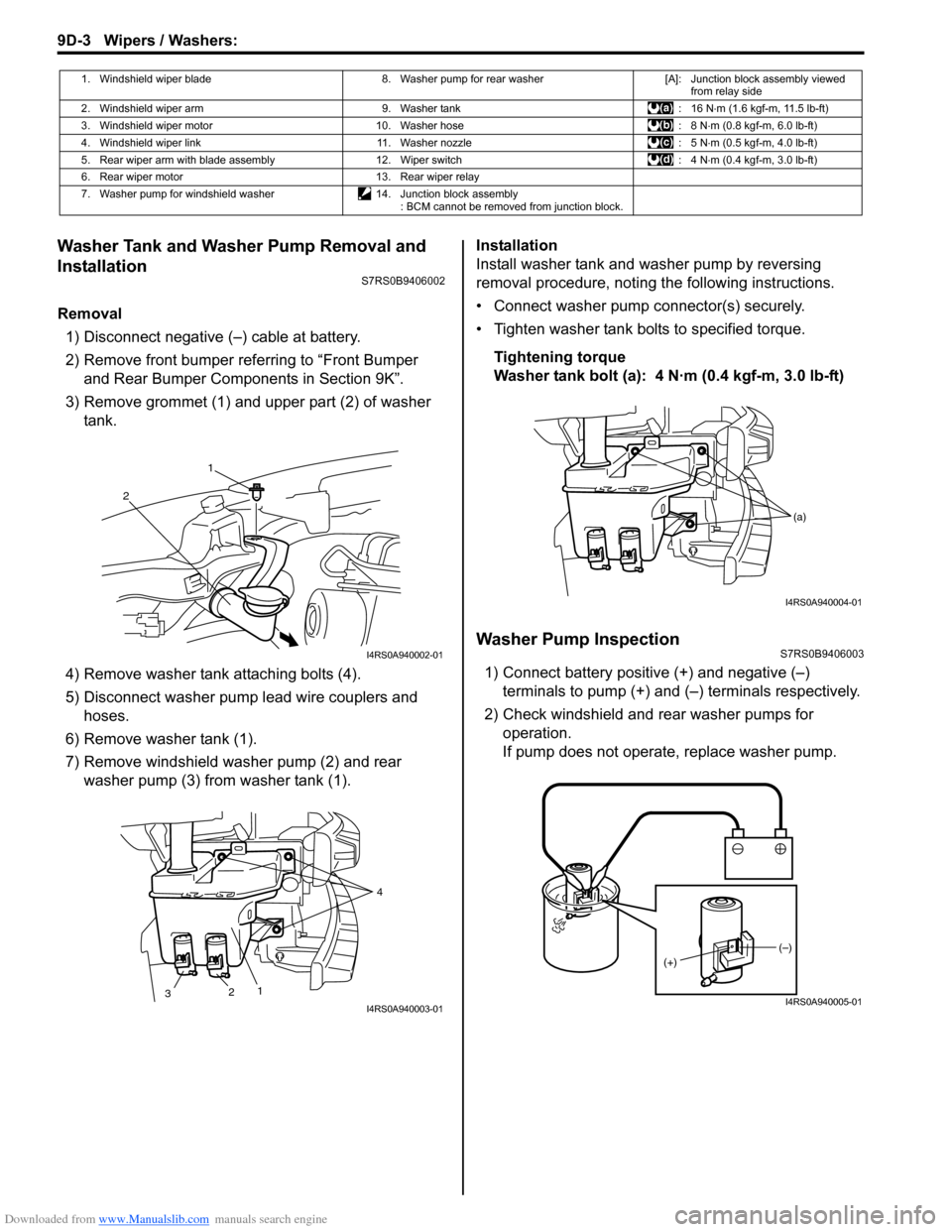
Washer Tank and Washer Pump Removal and
Installation
S7RS0B9406002
Removal1) Disconnect negative (–) cable at battery.
2) Remove front bumper referring to “Front Bumper and Rear Bumper Components in Section 9K”.
3) Remove grommet (1) and upper part (2) of washer tank.
4) Remove washer tank attaching bolts (4).
5) Disconnect washer pump lead wire couplers and hoses.
6) Remove washer tank (1).
7) Remove windshield washer pump (2) and rear washer pump (3) from washer tank (1). Installation
Install washer tank and washer pump by reversing
removal procedure, noting the following instructions.
• Connect washer pump connector(s) securely.
• Tighten washer tank bolts to specified torque.
Tightening torque
Washer tank bolt (a): 4 N·m (0.4 kgf-m, 3.0 lb-ft)
Washer Pump InspectionS7RS0B9406003
1) Connect battery positive (+) and negative (–) terminals to pump (+) and (–) terminals respectively.
2) Check windshield and rear washer pumps for
operation.
If pump does not operate, replace washer pump.
1. Windshield wiper blade 8. Washer pump for rear washer[A]: Junction block assembly viewed
from relay side
2. Windshield wiper arm 9. Washer tank: 16 N⋅m (1.6 kgf-m, 11.5 lb-ft)
3. Windshield wiper motor 10. Washer hose : 8 N⋅m (0.8 kgf-m, 6.0 lb-ft)
4. Windshield wiper link 11. Washer nozzle : 5 N⋅m (0.5 kgf-m, 4.0 lb-ft)
5. Rear wiper arm with blade assembly 12. Wiper switch : 4 N⋅m (0.4 kgf-m, 3.0 lb-ft)
6. Rear wiper motor 13. Rear wiper relay
7. Washer pump for windshield washer 14. Junction block assembly
: BCM cannot be removed from junction block.
1
2
I4RS0A940002-01
2 1 4
3
I4RS0A940003-01
(a)
I4RS0A940004-01
(–)
(+)
I4RS0A940005-01
Page 1329 of 1496
Downloaded from www.Manualslib.com manuals search engine Glass / Windows / Mirrors: 9E-2
• Eyeleteer
• Piano string
• Windshield knife
• Brush for primer application (2 pcs)
•Knife
• Rubber sucker grip
• Sealant gun (for filling adhesive)
• Putty spatula (for correcting adhered parts)
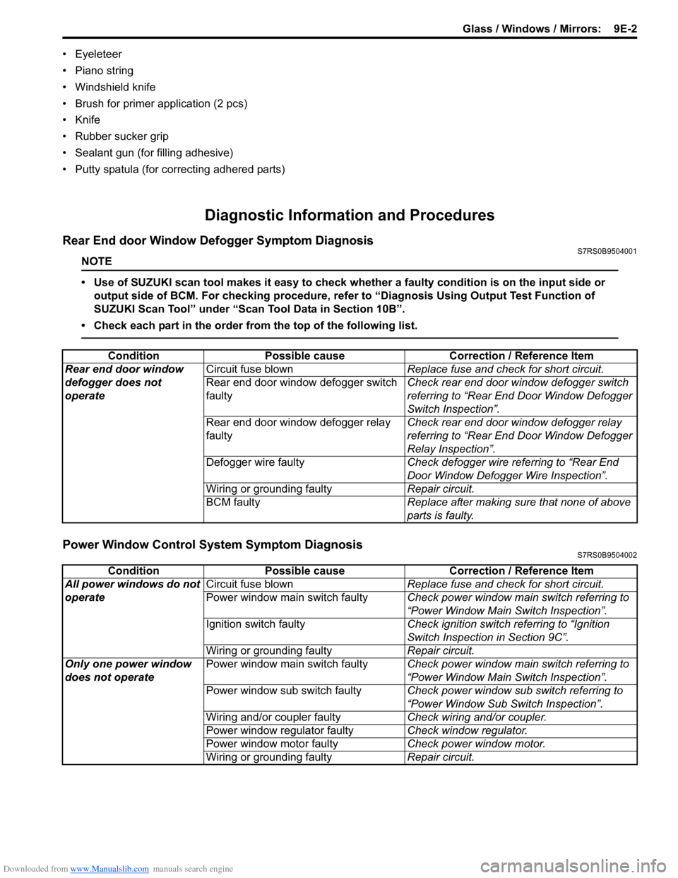
Diagnostic Information and Procedures
Rear End door Window Defogger Symptom DiagnosisS7RS0B9504001
NOTE
• Use of SUZUKI scan tool makes it easy to check whether a faulty condition is on the input side or
output side of BCM. For checking procedure, re fer to “Diagnosis Using Output Test Function of
SUZUKI Scan Tool” under “Scan Tool Data in Section 10B”.
• Check each part in the order from the top of the following list.
Power Window Control System Symptom DiagnosisS7RS0B9504002
Condition Possible cause Correction / Reference Item
Rear end door window
defogger does not
operate Circuit fuse blown
Replace fuse and check for short circuit.
Rear end door window defogger switch
faulty Check rear end door window defogger switch
referring to “Rear End Door Window Defogger
Switch Inspection”.
Rear end door window defogger relay
faulty Check rear end door window defogger relay
referring to “Rear End Door Window Defogger
Relay Inspection”.
Defogger wire faulty Check defogger wire referring to “Rear End
Door Window Defogger Wire Inspection”.
Wiring or grounding faulty Repair circuit.
BCM faulty Replace after making sure that none of above
parts is faulty.
ConditionPossible cause Correction / Reference Item
All power windows do not
operate Circuit fuse blown
Replace fuse and check for short circuit.
Power window main switch faulty Check power window main switch referring to
“Power Window Main Switch Inspection”.
Ignition switch faulty Check ignition switch referring to “Ignition
Switch Inspection in Section 9C”.
Wiring or grounding faulty Repair circuit.
Only one power window
does not operate Power window main switch faulty
Check power window main switch referring to
“Power Window Main Switch Inspection”.
Power window sub switch faulty Check power window sub switch referring to
“Power Window Sub Switch Inspection”.
Wiring and/or coupler faulty Check wiring and/or coupler.
Power window regulator faulty Check window regulator.
Power window motor faulty Check power window motor.
Wiring or grounding faulty Repair circuit.
Page 1330 of 1496
Downloaded from www.Manualslib.com manuals search engine 9E-3 Glass / Windows / Mirrors:
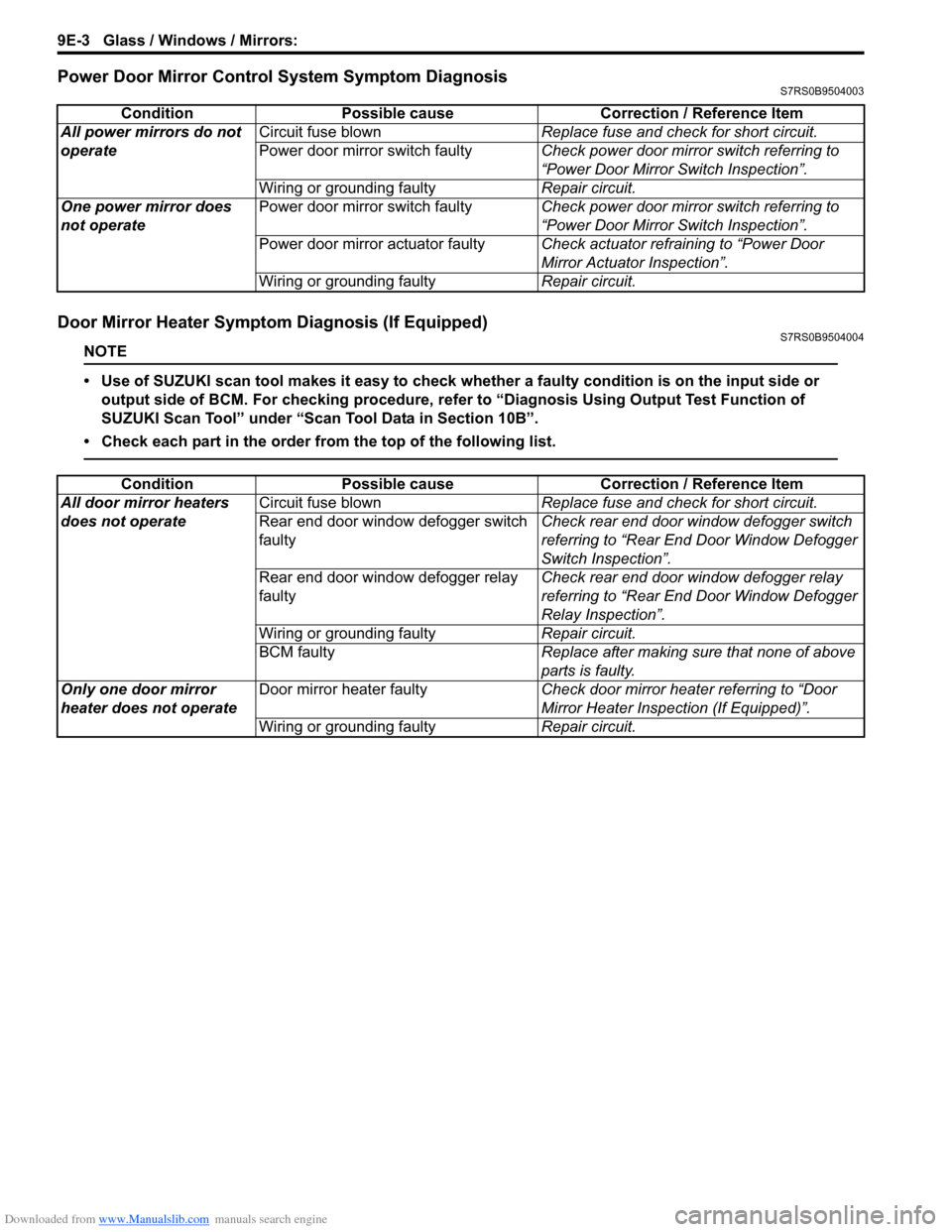
Power Door Mirror Control System Symptom DiagnosisS7RS0B9504003
Door Mirror Heater Symptom Diagnosis (If Equipped)S7RS0B9504004
NOTE
• Use of SUZUKI scan tool makes it easy to check whether a faulty condition is on the input side or
output side of BCM. For checking procedure, re fer to “Diagnosis Using Output Test Function of
SUZUKI Scan Tool” under “Scan Tool Data in Section 10B”.
• Check each part in the order from the top of the following list.
Condition Possible cause Correction / Reference Item
All power mirrors do not
operate Circuit fuse blown
Replace fuse and check for short circuit.
Power door mirror switch faulty Check power door mirror switch referring to
“Power Door Mirror Switch Inspection”.
Wiring or grounding faulty Repair circuit.
One power mirror does
not operate Power door mirror switch faulty
Check power door mirror switch referring to
“Power Door Mirror Switch Inspection”.
Power door mirror actuator faulty Check actuator refraining to “Power Door
Mirror Actuator Inspection”.
Wiring or grounding faulty Repair circuit.
ConditionPossible cause Correction / Reference Item
All door mirror heaters
does not operate Circuit fuse blown
Replace fuse and check for short circuit.
Rear end door window defogger switch
faulty Check rear end door window defogger switch
referring to “Rear End Door Window Defogger
Switch Inspection”.
Rear end door window defogger relay
faulty Check rear end door window defogger relay
referring to “Rear End Door Window Defogger
Relay Inspection”.
Wiring or grounding faulty Repair circuit.
BCM faulty Replace after making sure that none of above
parts is faulty.
Only one door mirror
heater does not operate Door mirror heater faulty
Check door mirror heater referring to “Door
Mirror Heater Inspection (If Equipped)”.
Wiring or grounding faulty Repair circuit.
Page 1332 of 1496
Downloaded from www.Manualslib.com manuals search engine 9E-5 Glass / Windows / Mirrors:
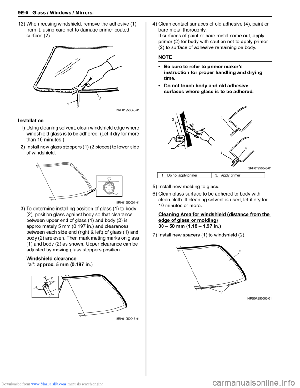
12) When reusing windshield, remove the adhesive (1) from it, using care not to damage primer coated
surface (2).
Installation 1) Using cleaning solvent, clean windshield edge where windshield glass is to be adhered. (Let it dry for more
than 10 minutes.)
2) Install new glass stoppers (1) (2 pieces) to lower side of windshield.
3) To determine installing position of glass (1) to body (2), position glass against body so that clearance
between upper end of glass (1) and body (2) is
approximately 5 mm (0.197 in.) and clearances
between each side end (right & left) of glass (1) and
body (2) are even. Then mark mating marks on glass
(1) and body (2) as shown. Upper clearance can be
adjusted by moving glass stoppers position.
Windshield clearance
“a”: approx. 5 mm (0.197 in.) 4) Clean contact surfaces of old adhesive (4), paint or
bare metal thoroughly.
If surfaces of paint or ba re metal come out, apply
primer (2) for body with caution not to apply primer
(2) to surface of adhesive remaining on body.
NOTE
• Be sure to refer to primer maker’s instruction for proper handling and drying
time.
• Do not touch body and old adhesive surfaces where glass is to be adhered.
5) Install new molding to glass.
6) Clean glass surface to be adhered to body with clean cloth. If cleaning solvent is used, let it dry for
10 minutes or more.
Cleaning Area for windshie ld (distance from the
edge of glass or molding)
30 – 50 mm (1.18 – 1.97 in.)
7) Install new spacers (1) to windshield (2).
I2RH01950043-01
1
I4RH01950001-01
2
1“a”
I2RH01950045-01
1. Do not apply primer 3. Apply primer
I2RH01950046-01
2
1I4RS0A950002-01
Page 1347 of 1496
Downloaded from www.Manualslib.com manuals search engine Security and Locks: 9F-1
Body, Cab and Accessories
Security and Locks
General Description
Key Coding ConstructionS7RS0B9601001
Key Usage and Identification
Key is used for ignition and door lock cylinders. Key is cut on both edges to make them reversible.
Key identification is obtained from five character key code stamped on key code tag. Using this key code, key code
cutting combination can be determined from a code list (ava ilable to owners of key cutting equipment from suppliers).
Rear End Door Opener System DescriptionS7RS0B9601002
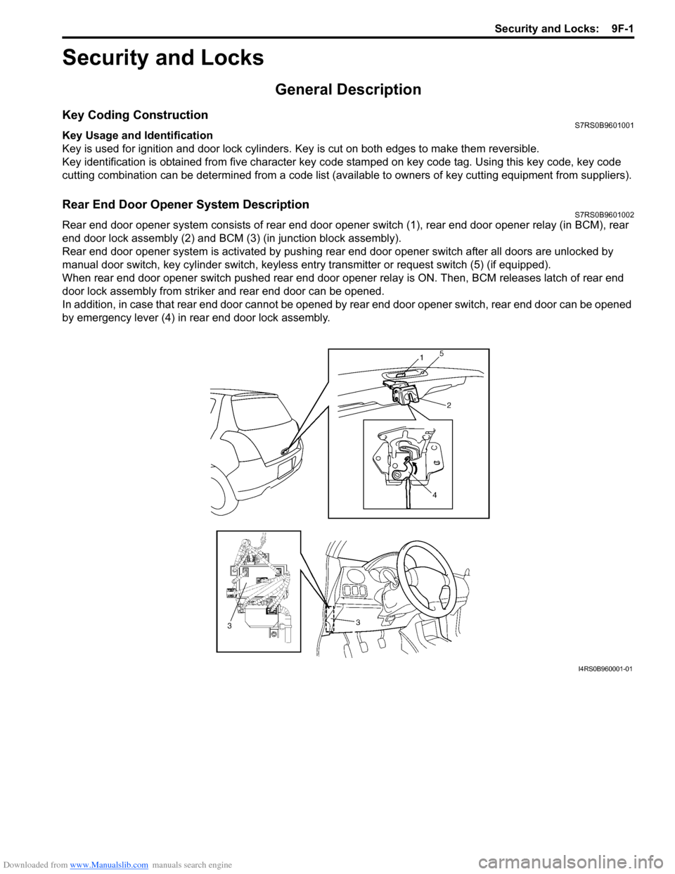
Rear end door opener system consists of rear end door opener switch (1), rear end door opener relay (in BCM), rear
end door lock assembly (2) and BCM (3) (in junction block assembly).
Rear end door opener system is activated by pushing re ar end door opener switch after all doors are unlocked by
manual door switch, key cylinder s witch, keyless entry transmitter or request switch (5) (if equipped).
When rear end door opener switch pushed rear end door opener relay is ON. Then, BCM releases latch of rear end
door lock assembly from striker and rear end door can be opened.
In addition, in case that rear end door cannot be opened by rear end door opener switch, rear end door can be opened
by emergency lever (4) in rear end door lock assembly.
I4RS0B960001-01