Rear axle SUZUKI SWIFT 2005 2.G Service Service Manual
[x] Cancel search | Manufacturer: SUZUKI, Model Year: 2005, Model line: SWIFT, Model: SUZUKI SWIFT 2005 2.GPages: 1496, PDF Size: 34.44 MB
Page 803 of 1496
Downloaded from www.Manualslib.com manuals search engine Automatic Transmission/Transaxle: 5A-159
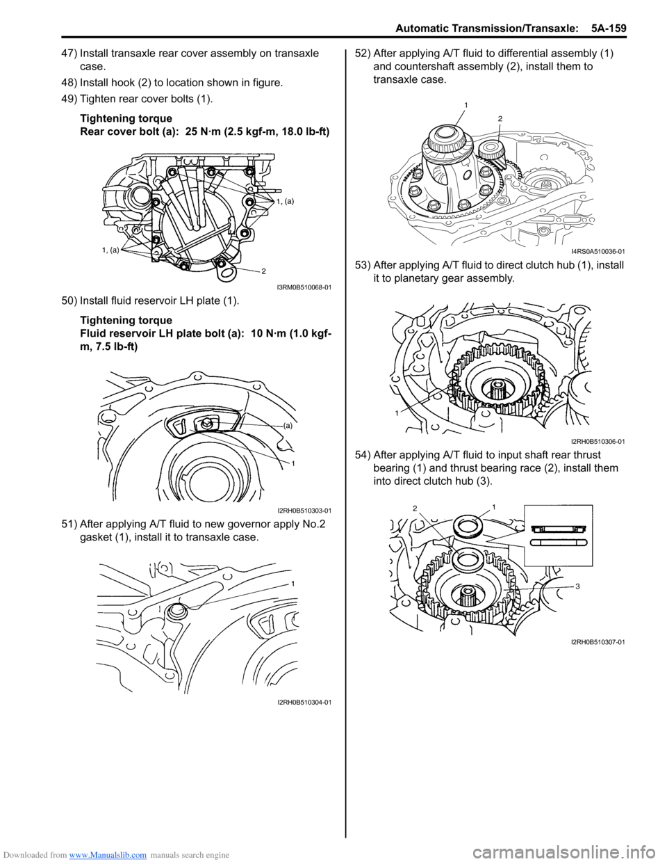
47) Install transaxle rear cover assembly on transaxle case.
48) Install hook (2) to location shown in figure.
49) Tighten rear cover bolts (1).
Tightening torque
Rear cover bolt (a): 25 N·m (2.5 kgf-m, 18.0 lb-ft)
50) Install fluid reservoir LH plate (1). Tightening torque
Fluid reservoir LH plate bolt (a): 10 N·m (1.0 kgf-
m, 7.5 lb-ft)
51) After applying A/T fluid to new governor apply No.2 gasket (1), install it to transaxle case. 52) After applying A/T fluid to differential assembly (1)
and countershaft assembly (2), install them to
transaxle case.
53) After applying A/T fluid to di rect clutch hub (1), install
it to planetary gear assembly.
54) After applying A/T fluid to input shaft rear thrust
bearing (1) and thrust bearing race (2), install them
into direct clutch hub (3).
I3RM0B510068-01
I2RH0B510303-01
I2RH0B510304-01
1
2
I4RS0A510036-01
I2RH0B510306-01
I2RH0B510307-01
Page 811 of 1496

Downloaded from www.Manualslib.com manuals search engine Automatic Transmission/Transaxle: 5A-167
Specifications
Tightening Torque SpecificationsS7RS0B5107001
NOTE
The specified tightening torque is also described in the following.
“Select Cable Components”
“Automatic Transaxle Unit Components”
“Automatic Transaxle Assembly Components”
“Oil Pump Assembly Components”
“Transaxle Rear Cover (O/D and 2nd Coast Brake Piston) Assembly Components”
“Valve Body Assembly Components”
“Differential Assembly Components”
Reference:
For the tightening torque of fastener not specified in this section, refer to “Fasteners Information in Section 0A”.
Fastening part
Tightening torque
Note
N ⋅mkgf-mlb-ft
A/T fluid drain plug 171.7 12.5 �) / �) / �)
Transmission range sensor bolt 5.5 0.55 4.0�) / �)
Output shaft speed sensor bolt 131.3 9.5 �) / �)
Input shaft speed sensor bolt 5.5 0.55 4.0�)
Valve body harness connector bolt 7.00.7 5.0 �)
Shift solenoid bolt 111.1 8.0 �)
Oil strainer bolt 101.0 7.5 �) / �)
Oil pan bolt 7.00.7 5.0 �) / �)
Transaxle and engine fastening bolt and nut 85 8.5 61.5�)
Drive plate to torque converter bolt 252.5 18.0 �)
Transaxle stiffener bolt 555.5 40�)
Starter motor bolt and nut 505.0 36.5 �)
Oil pump subassembly bolt 101.0 7.5 �)
Rear cover plug 7.5 0.75 5.5�)
Solenoid valve bolt 111.1 8.0 �)
Final gear bolt 787.8 56.5 �)
Torque converter housing plug 7.5 0.75 5.5�)
Lubrication tube clamp bolt 5.5 0.55 4.0�)
Fluid reservoir RH plate bolt 5.5 0.55 4.0�)
Torque converter housing bolt 292.9 21�) / �) / �)
Manual detent spring bolt 101.0 7.5 �)
Parking lock pawl bracket bolt 7.5 0.75 5.5�)
Rear cover bolt 252.5 18.0 �)
Fluid reservoir LH plate bolt 101.0 7.5 �)
Oil pump assembly bolt 252.5 18.0 �)
Transaxle case plug 7.5 0.75 5.5�)
Valve body harness connector bolt 5.5 0.55 4.0�)
Valve body bolt 111.1 8.0 �)
Fluid outlet union 252.5 18.0 �)
Fluid cooler pipe union bolt 222.2 16.0 �)
Fluid cooler pipe bracket bolt 101.0 7.5 �)
Fluid filler tube bolt 101.0 7.5 �)
Input shaft speed sensor bolt 111.1 8.0 �)
Harness bracket bolt 232.3 17.0 �)
Select cable clamp bolt 101.0 7.5 �)
Transmission range sensor lock nut 70.7 5.0 �)
Manual select lever nut 131.3 9.5 �)
Engine mounting LH bracket bolt 555.5 40.0
�)
Page 812 of 1496
Downloaded from www.Manualslib.com manuals search engine 5A-168 Automatic Transmission/Transaxle:
Special Tools and Equipment
Recommended Service MaterialS7RS0B5108001
NOTE
Required service material is also described in the following.
“Select Cable Components”
“Automatic Transaxle Unit Components”
“Automatic Transaxle Assembly Components”
“Oil Pump Assembly Components”
“Direct Clutch Assembly Components”
“Forward and Reverse Clutch Assembly Components”
“2nd Brake Piston Assembly Components”
“Transaxle Rear Cover (O/D and 2nd Coast Brake Piston) Assembly Components”
“Countershaft Assembly Components”
“Valve Body Assembly Components”
“Differential Assembly Components”
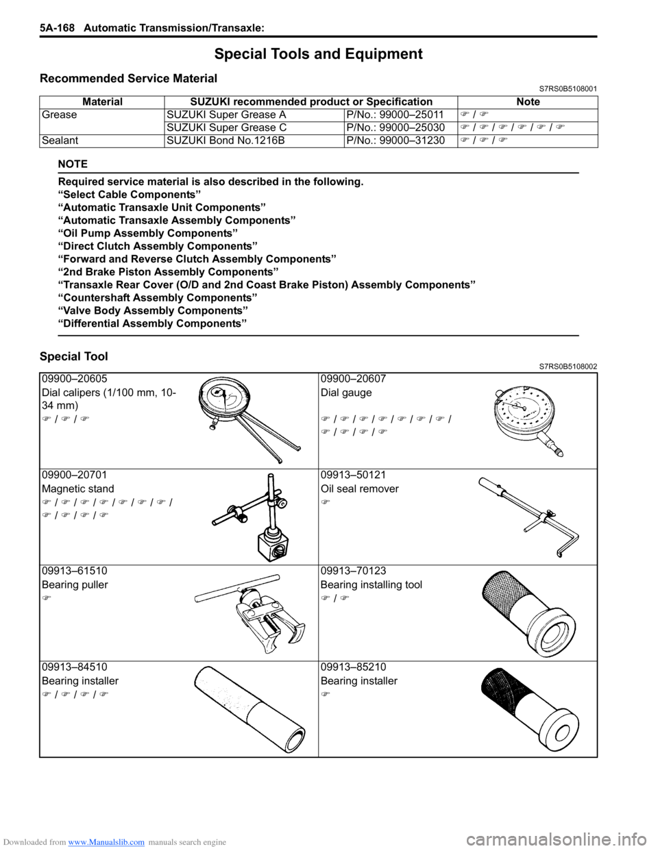
Special ToolS7RS0B5108002
Material SUZUKI recommended product or Specification Note
Grease SUZUKI Super Grease A P/No.: 99000–25011�) / �)
SUZUKI Super Grease C P/No.: 99000–25030�) / �) / �) / �) / �) / �)
Sealant SUZUKI Bond No.1216B P/No.: 99000–31230�) / �) / �)
09900–20605 09900–20607
Dial calipers (1/100 mm, 10-
34 mm) Dial gauge
�) / �) / �)�) / �) / �) / �) / �) / �) / �) /
�) / �) / �) / �)
09900–20701 09913–50121
Magnetic stand Oil seal remover
�) / �) / �) / �) / �) / �) / �) /
�) / �) / �) / �) �)
09913–61510 09913–70123
Bearing puller Bearing installing tool
�)�) / �)
09913–84510 09913–85210
Bearing installer Bearing installer
�) / �) / �) / �)�)
Page 822 of 1496
![SUZUKI SWIFT 2005 2.G Service Service Manual Downloaded from www.Manualslib.com manuals search engine 5B-8 Manual Transmission/Transaxle:
Manual Transaxle Unit ComponentsS7RS0B5206008
13
6(a)
5
14(c)
114 7
(b)
12
7(b)
8
2
5 [A]
1
10
6
(a)
(a)
( SUZUKI SWIFT 2005 2.G Service Service Manual Downloaded from www.Manualslib.com manuals search engine 5B-8 Manual Transmission/Transaxle:
Manual Transaxle Unit ComponentsS7RS0B5206008
13
6(a)
5
14(c)
114 7
(b)
12
7(b)
8
2
5 [A]
1
10
6
(a)
(a)
(](/img/20/7607/w960_7607-821.png)
Downloaded from www.Manualslib.com manuals search engine 5B-8 Manual Transmission/Transaxle:
Manual Transaxle Unit ComponentsS7RS0B5206008
13
6(a)
5
14(c)
114 7
(b)
12
7(b)
8
2
5 [A]
1
10
6
(a)
(a)
(b)3
9
9
(b)
(d)
I6RS0C520004-03
[A]: Forward
7. Engine left mounting bracket bolt and nuts 14. Clutch operating cylinder bolt
1. Engine 8. Clutch housing lower plate : 85 N⋅m (8.5 kgf-m, 61.5 lb-ft)
2. Transaxle 9. Engine rear mounting bracket bolts : 55 N⋅m (5.5 kgf-m, 40.0 lb-ft)
3. Engine rear mounting and bracket 10. Transaxle to engine nut : 23 N⋅m (2.3 kgf-m, 17.0 lb-ft)
4. Back up light switch connector 11. Ground cable : 11 N⋅m (1.1 kgf-m, 8.0 lb-ft)
5. Clutch operating cylinder 12. Engine left mounting bracket
6. Transaxle to engine bolt 13. Gear shift & select control cables
Page 824 of 1496
Downloaded from www.Manualslib.com manuals search engine 5B-10 Manual Transmission/Transaxle:
16) Remove engine under covers.
17) Support transaxle with transmission jack.
18) Remove transaxle to engine bolts and nut of lower side.
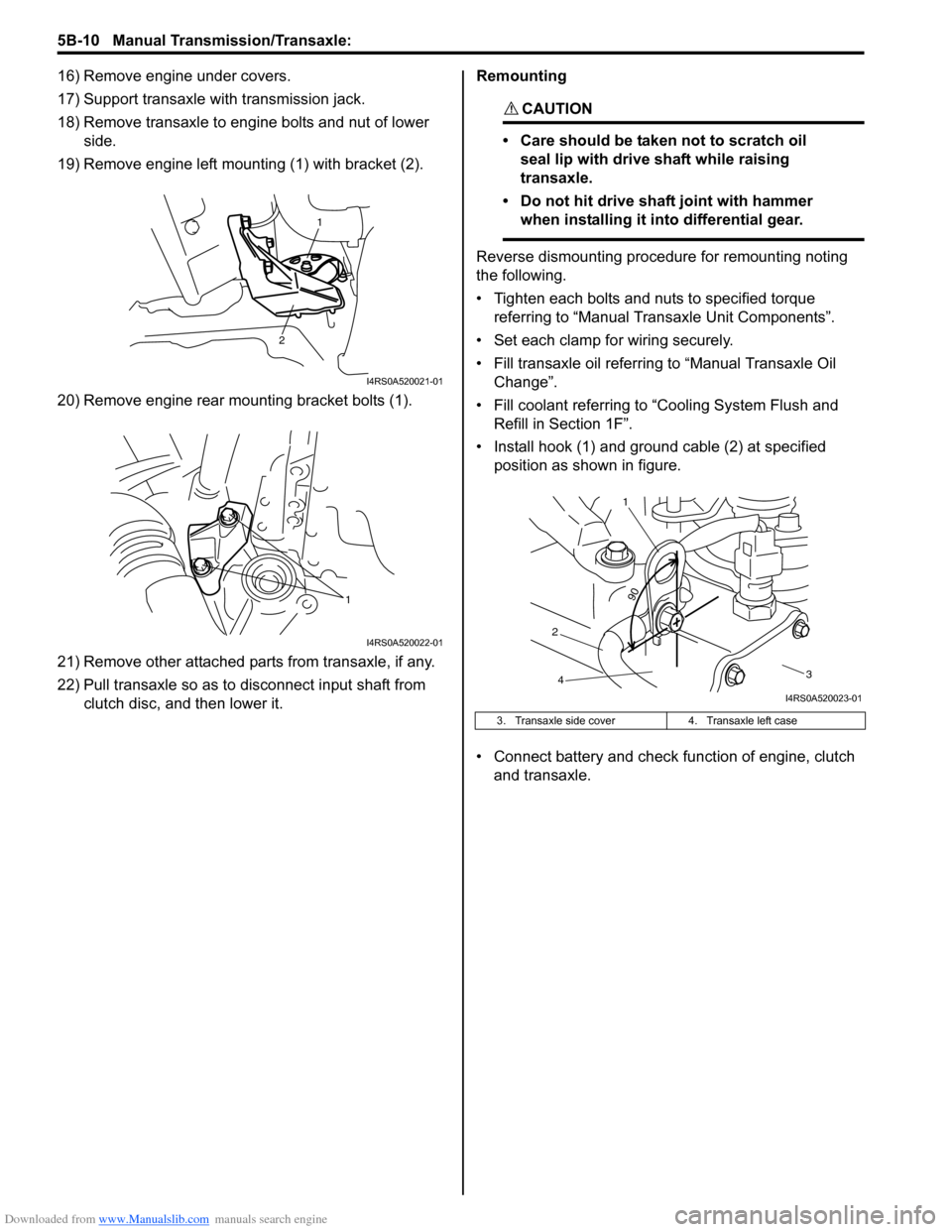
19) Remove engine left mounting (1) with bracket (2).
20) Remove engine rear mounting bracket bolts (1).
21) Remove other attached parts from transaxle, if any.
22) Pull transaxle so as to disconnect input shaft from clutch disc, and then lower it. Remounting
CAUTION!
• Care should be taken not to scratch oil
seal lip with drive shaft while raising
transaxle.
• Do not hit drive shaft joint with hammer when installing it into differential gear.
Reverse dismounting procedure for remounting noting
the following.
• Tighten each bolts and nuts to specified torque referring to “Manual Transaxle Unit Components”.
• Set each clamp for wiring securely.
• Fill transaxle oil referring to “Manual Transaxle Oil
Change”.
• Fill coolant referring to “Cooling System Flush and
Refill in Section 1F”.
• Install hook (1) and ground cable (2) at specified position as shown in figure.
• Connect battery and check function of engine, clutch
and transaxle.
1
2
I4RS0A520021-01
1
I4RS0A520022-01
3. Transaxle side cover 4. Transaxle left case
90
1
2 3
4
I4RS0A520023-01
Page 1206 of 1496
Downloaded from www.Manualslib.com manuals search engine 9A-35 Wiring Systems:
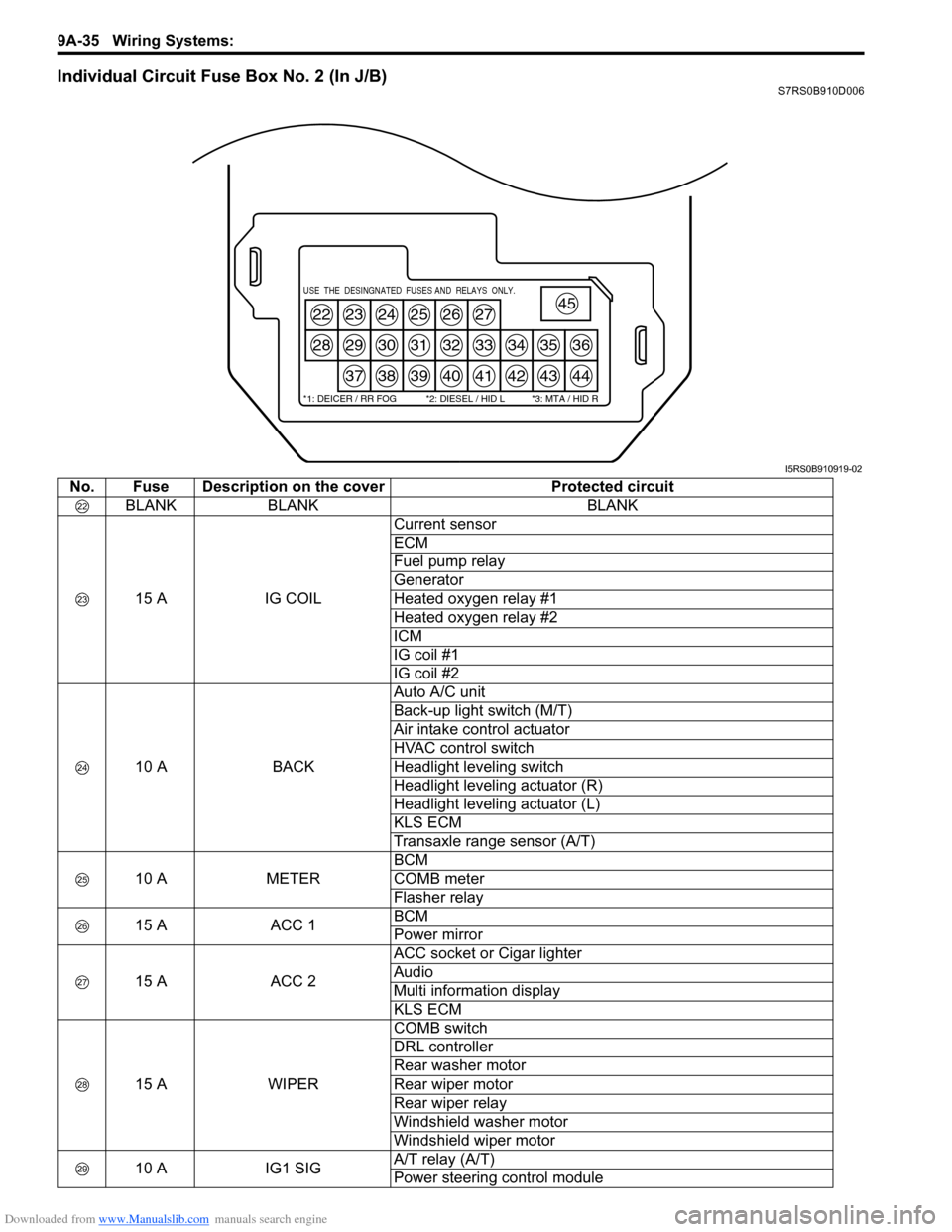
Individual Circuit Fuse Box No. 2 (In J/B)S7RS0B910D006
22
28
23
29
37
24
30
38
25
31
39
26
32
40
27
33
41
34
42
35
43
36
44
45USE THE DESINGNATED FUSES AND RELAYS ONLY.
*1: DEICER / RR FOG *2: DIESEL / HID L *3: MTA / HID R
I5RS0B910919-02
No. Fuse Description on the coverProtected circuit
BLANK BLANK BLANK
15 A IG COILCurrent sensor
ECM
Fuel pump relay
Generator
Heated oxygen relay #1
Heated oxygen relay #2
ICM
IG coil #1
IG coil #2
10 A BACKAuto A/C unit
Back-up light switch (M/T)
Air intake control actuator
HVAC control switch
Headlight leveling switch
Headlight leveling actuator (R)
Headlight leveling actuator (L)
KLS ECM
Transaxle range sensor (A/T)
10 A METERBCM
COMB meter
Flasher relay
15 A ACC 1BCM
Power mirror
15 A ACC 2ACC socket or Cigar lighter
Audio
Multi information display
KLS ECM
15 A WIPERCOMB switch
DRL controller
Rear washer motor
Rear wiper motor
Rear wiper relay
Windshield washer motor
Windshield wiper motor
10 A IG1 SIGA/T relay (A/T)
Power steering control module
Page 1384 of 1496
Downloaded from www.Manualslib.com manuals search engine 9K-7 Body Structure:
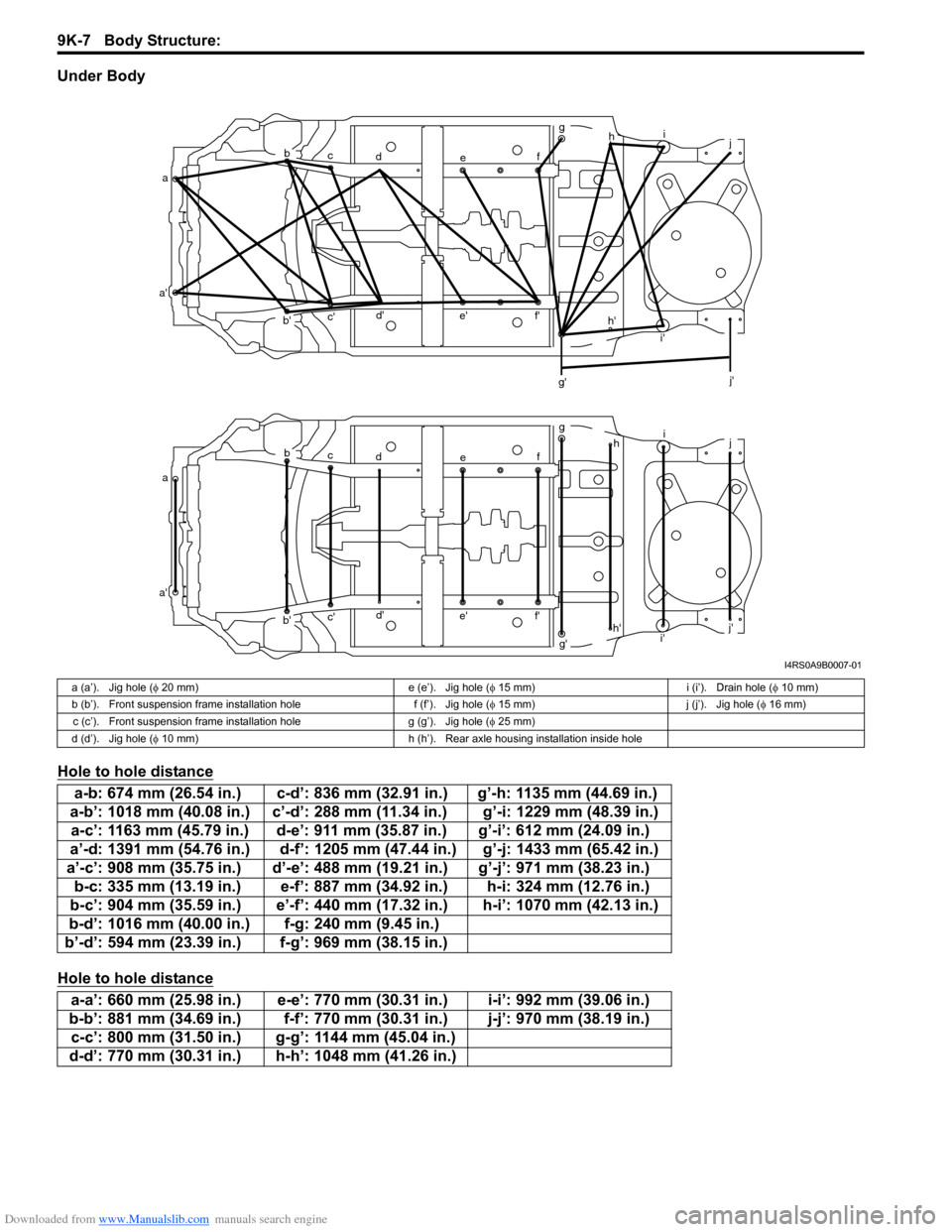
Under Body
Hole to hole distance
Hole to hole distance
ab
c d e fg
h i
j
a' b'c'
d'
e' f'
g' i'
j'
a b
c d e fg
hi
j
a' b'c'
d'
e' f'
g'h'
i' j'
h'
I4RS0A9B0007-01
a (a’). Jig hole (
φ 20 mm) e (e’). Jig hole ( φ 15 mm) i (i’). Drain hole ( φ 10 mm)
b (b’). Front suspension frame installation hole f (f’). Jig hole ( φ 15 mm) j (j’). Jig hole ( φ 16 mm)
c (c’). Front suspension frame installation hole g (g’). Jig hole (φ 25 mm)
d (d’). Jig hole ( φ 10 mm) h (h’). Rear axle housing installation inside hole
a-b: 674 mm (26.54 in.) c-d’: 836 mm (32.91 in.) g’-h: 1135 mm (44.69 in.)
a-b’: 1018 mm (40.08 in.) c’-d’: 288 mm (11.34 in.) g’-i: 1229 mm (48.39 in.) a-c’: 1163 mm (45.79 in.) d-e’: 911 mm (35.87 in.) g’-i’: 612 mm (24.09 in.)
a’-d: 1391 mm (54.76 in.) d-f’: 1205 mm (47.44 in.) g’-j: 1433 mm (65.42 in.)
a’-c’: 908 mm (35.75 in.) d’-e’: 488 mm (1 9.21 in.) g’-j’: 971 mm (38.23 in.)
b-c: 335 mm (13.19 in.) e-f’: 887 mm (34.92 in.) h-i: 324 mm (12.76 in.)
b-c’: 904 mm (35.59 in.) e’-f’: 440 mm (17.32 in.) h-i’: 1070 mm (42.13 in.)
b-d’: 1016 mm (40.00 in.) f-g: 240 mm (9.45 in.)
b’-d’: 594 mm (23.39 in.) f-g’: 969 mm (38.15 in.)
a-a’: 660 mm (25.98 in.) e-e’: 770 mm (30.31 in.) i-i’: 992 mm (39.06 in.)
b-b’: 881 mm (34.69 in.) f-f’: 770 mm (30.31 in.) j-j’: 970 mm (38.19 in.) c-c’: 800 mm (31.50 in.) g-g’: 1144 mm (45.04 in.)
d-d’: 770 mm (30.31 in.) h-h’: 1048 mm (41.26 in.)
Page 1385 of 1496
Downloaded from www.Manualslib.com manuals search engine Body Structure: 9K-8
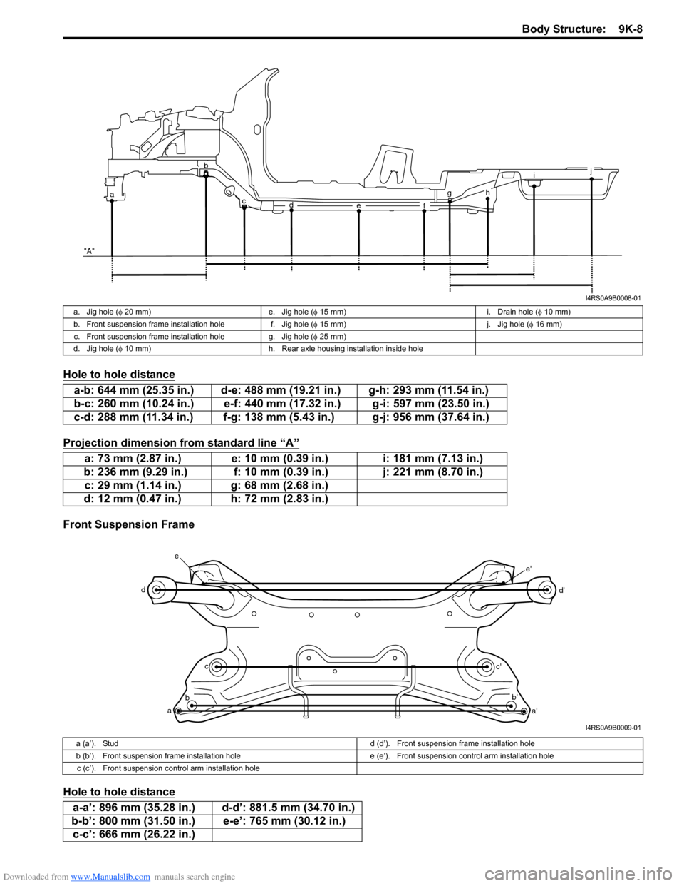
Hole to hole distance
Projection dimension from standard line “A”
Front Suspension Frame
Hole to hole distance
i
g
f
e
d
c
ab
"A"j
h
I4RS0A9B0008-01
a. Jig hole ( φ 20 mm) e. Jig hole ( φ 15 mm) i. Drain hole ( φ 10 mm)
b. Front suspension frame installation hole f. Jig hole (φ 15 mm) j. Jig hole (φ 16 mm)
c. Front suspension frame installation hole g. Jig hole ( φ 25 mm)
d. Jig hole ( φ 10 mm) h. Rear axle housing installation inside hole
a-b: 644 mm (25.35 in.) d-e: 488 mm (19.21 in.) g-h: 293 mm (11.54 in.)
b-c: 260 mm (10.24 in.) e-f: 440 mm (17.32 in.) g-i: 597 mm (23.50 in.)
c-d: 288 mm (11.34 in.) f-g: 138 mm (5.43 in.) g-j: 956 mm (37.64 in.)
a: 73 mm (2.87 in.) e: 10 mm (0.39 in.) i: 181 mm (7.13 in.)
b: 236 mm (9.29 in.) f: 10 mm (0.39 in.) j: 221 mm (8.70 in.) c: 29 mm (1.14 in.) g: 68 mm (2.68 in.)
d: 12 mm (0.47 in.) h: 72 mm (2.83 in.)
a b c
d
e
a'
b'
c' d'
e'
I4RS0A9B0009-01
a (a’). Stud
d (d’). Front suspension frame installation hole
b (b’). Front suspension frame installation hole e (e’). Front suspension control arm installation hole
c (c’). Front suspension control arm installation hole
a-a’: 896 mm (35.28 in.) d-d’: 881.5 mm (34.70 in.)
b-b’: 800 mm (31.50 in.) e-e’: 765 mm (30.12 in.) c-c’: 666 mm (26.22 in.)