torque specification SUZUKI SWIFT 2005 2.G Service Repair Manual
[x] Cancel search | Manufacturer: SUZUKI, Model Year: 2005, Model line: SWIFT, Model: SUZUKI SWIFT 2005 2.GPages: 1496, PDF Size: 34.44 MB
Page 663 of 1496
Downloaded from www.Manualslib.com manuals search engine Automatic Transmission/Transaxle: 5A-19
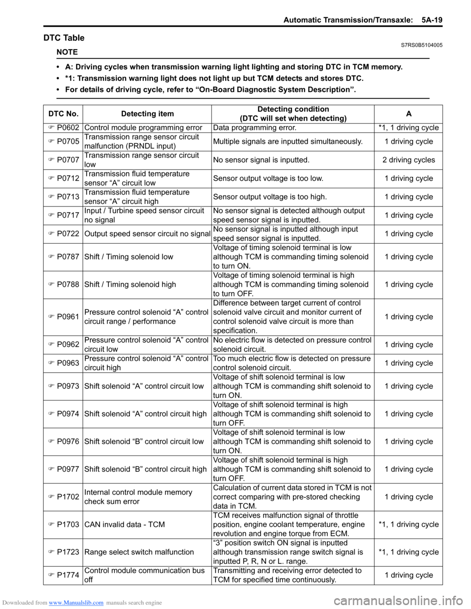
DTC TableS7RS0B5104005
NOTE
• A: Driving cycles when transmission warning light lighting and storing DTC in TCM memory.
• *1: Transmission warning light does not light up but TCM detects and stores DTC.
• For details of driving cycle, refer to “On-Board Diagnostic System Description”.
DTC No.Detecting item Detecting condition
(DTC will set when detecting) A
) P0602 Control module programming error D ata programming error. *1, 1 driving cycle
) P0705 Transmission range sensor circuit
malfunction (PRNDL input) Multiple signals are inputted
simultaneously. 1 driving cycle
) P0707 Transmission range sensor circuit
low No sensor signal is inputted.
2 driving cycles
) P0712 Transmission fluid temperature
sensor “A” circuit low Sensor output voltage is too low.
1 driving cycle
) P0713 Transmission fluid temperature
sensor “A” circuit high Sensor output voltage is too high.
1 driving cycle
) P0717 Input / Turbine speed sensor circuit
no signal No sensor signal is detected although output
speed sensor signal is inputted.
1 driving cycle
) P0722 Output speed sensor circuit no signal No sensor signal is inputted although input
speed sensor signal is inputted. 1 driving cycle
) P0787 Shift / Timing solenoid low Voltage of timing solenoid terminal is low
although TCM is commanding timing solenoid
to turn ON. 1 driving cycle
) P0788 Shift / Timing solenoid high Voltage of timing solenoid terminal is high
although TCM is commanding timing solenoid
to turn OFF. 1 driving cycle
) P0961 Pressure control solenoid “A” control
circuit range / performance Difference between target current of control
solenoid valve circuit and monitor current of
control solenoid valve circuit is more than
specification.
1 driving cycle
) P0962 Pressure control solenoid “A” control
circuit low No electric flow is detected on pressure control
solenoid circuit.
1 driving cycle
) P0963 Pressure control solenoid “A” control
circuit high Too much electric flow is detected on pressure
control solenoid circuit.
1 driving cycle
) P0973 Shift solenoid “A” control circuit low Voltage of shift solenoid terminal is low
although TCM is commanding shift solenoid to
turn ON. 1 driving cycle
) P0974 Shift solenoid “A” control circuit high Voltage of shift solenoid terminal is high
although TCM is commanding shift solenoid to
turn OFF. 1 driving cycle
) P0976 Shift solenoid “B” control circuit low Voltage of shift solenoid terminal is low
although TCM is commanding shift solenoid to
turn ON. 1 driving cycle
) P0977 Shift solenoid “B” control circuit high Voltage of shift solenoid terminal is high
although TCM is commanding shift solenoid to
turn OFF. 1 driving cycle
) P1702 Internal control module memory
check sum error Calculation of current data stored in TCM is not
correct comparing with pre-stored checking
data in TCM.
1 driving cycle
) P1703 CAN invalid data - TCM TCM receives malfunction signal of throttle
position
, engine coolan t temperature, engine
revolution and engine torque from ECM. *1, 1 driving cycle
) P1723 Range select switch malfunction “3” position switch ON signal is inputted
although transmission range switch signal is
inputted P, R, N or L. range. *1, 1 driving cycle
) P1774 Control module communication bus
off Transmitting and receiving error detected to
TCM for specified time continuously.
1 driving cycle
Page 664 of 1496
Downloaded from www.Manualslib.com manuals search engine 5A-20 Automatic Transmission/Transaxle:
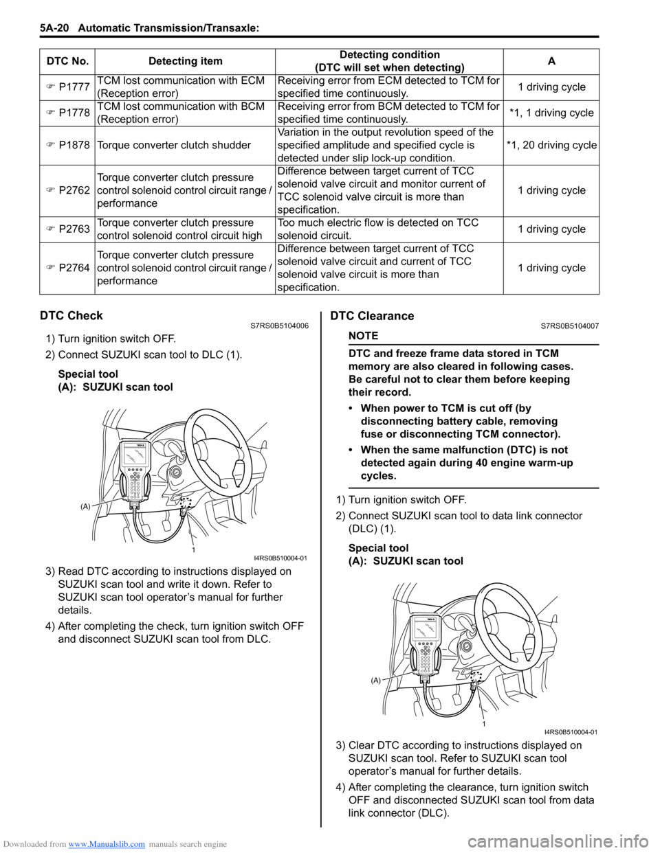
DTC CheckS7RS0B5104006
1) Turn ignition switch OFF.
2) Connect SUZUKI scan tool to DLC (1).
Special tool
(A): SUZUKI scan tool
3) Read DTC according to instructions displayed on SUZUKI scan tool and wr ite it down. Refer to
SUZUKI scan tool operator’s manual for further
details.
4) After completing the check, turn ignition switch OFF
and disconnect SUZUKI scan tool from DLC.
DTC ClearanceS7RS0B5104007
NOTE
DTC and freeze frame data stored in TCM
memory are also cleared in following cases.
Be careful not to clear them before keeping
their record.
• When power to TCM is cut off (by disconnecting battery cable, removing
fuse or disconnecting TCM connector).
• When the same malfunction (DTC) is not detected again during 40 engine warm-up
cycles.
1) Turn ignition switch OFF.
2) Connect SUZUKI scan tool to data link connector (DLC) (1).
Special tool
(A): SUZUKI scan tool
3) Clear DTC according to instructions displayed on SUZUKI scan tool. Refer to SUZUKI scan tool
operator’s manual for further details.
4) After completing the clearance, turn ignition switch OFF and disconnected SUZUKI scan tool from data
link connector (DLC).
)
P1777 TCM lost communication with ECM
(Reception error) Receiving error from ECM detected to TCM for
specified time continuously.
1 driving cycle
) P1778 TCM lost communication with BCM
(Reception error) Receiving error from BCM detected to TCM for
specified time continuously.
*1, 1 driving cycle
) P1878 Torque converter clutch shudder Variation in the output revolution speed of the
specified amplitude and specified cycle is
detected under slip lock-up condition. *1, 20 driving cycle
) P2762 Torque converter clutch pressure
control solenoid control circuit range /
performance Difference between target current of TCC
solenoid valve circuit and monitor current of
TCC solenoid valve ci
rcuit is more than
specification. 1 driving cycle
) P2763 Torque converter clutch pressure
control solenoid control circuit high Too much electric flow is detected on TCC
solenoid circuit.
1 driving cycle
) P2764 Torque converter clutch pressure
control solenoid control circuit range /
performance Difference between target current of TCC
solenoid valve circuit and current of TCC
solenoid valve circuit is more than
specification.
1 driving cycle
DTC No. Detecting item
Detecting condition
(DTC will set when detecting) A
1
(A)I4RS0B510004-01
1
(A)I4RS0B510004-01
Page 720 of 1496
Downloaded from www.Manualslib.com manuals search engine 5A-76 Automatic Transmission/Transaxle:
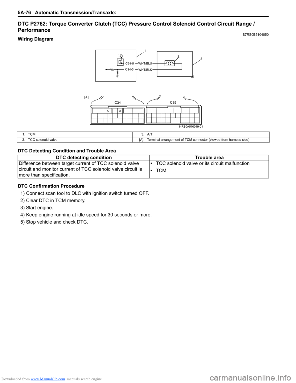
DTC P2762: Torque Converter Clutch (TCC) Pressure Control Solenoid Control Circuit Range /
Performance
S7RS0B5104050
Wiring Diagram
DTC Detecting Condition and Trouble Area
DTC Confirmation Procedure
1) Connect scan tool to DLC with ignition switch turned OFF.
2) Clear DTC in TCM memory.
3) Start engine.
4) Keep engine running at idle speed for 30 seconds or more.
5) Stop vehicle and check DTC.
12V
C34-5
C34-3
WHT/BLU
WHT/BLK
3
1
2
53
C34C35
[A]
I4RS0A510019-01
1. TCM
3. A/T
2. TCC solenoid valve [A]: Terminal arrangement of TCM connector (viewed from harness side)
DTC detecting conditionTrouble area
Difference between target current of TCC solenoid valve
circuit and monitor current of TCC solenoid valve circuit is
more than specification. • TCC solenoid valve or its circuit malfunction
•TCM
Page 757 of 1496

Downloaded from www.Manualslib.com manuals search engine Automatic Transmission/Transaxle: 5A-113
19) Remove transaxle case plug (1).
20) Remove torque converter housing bolts.
21) Remove torque converter housing (1) while tapping
around it lightly with plastic hammer.
22) Remove breather hose (1).
23) Remove breather union (2).
24) Measure input shaft thrust play. Apply dial gauge onto input shaft end (1) and
measure thrust play of input shaft.
When input shaft thrust play is out of specification,
select input shaft front th rust bearing with proper
thickness from among the list below and replace it.
Special tool
(A): 09900–20607
(B): 09900-20701
Input shaft thrust play
0.3 – 0.9 mm (0.012 – 0.035 in.)
Available input shaft front thrust bearing
thickness
: 3.45, 4.05 mm (0.136, 0.159 in.) 25) Remove oil pump assembly (1).
26) Remove direct clutch assembly (1).
27) Remove input shaft front thrust bearing (1).
NOTE
If input shaft front thrust bearing is not
found, it may have been taken out with oil
pump assembly.
I2RH0B510095-01
I3RM0B510060-01
1
2
I2RH0B510097-01
I2RH0B510098-01
I2RH0B510099-01
I2RH0B510100-01
I2RH0B510101-01
Page 766 of 1496
Downloaded from www.Manualslib.com manuals search engine 5A-122 Automatic Transmission/Transaxle:
Oil Pump Assembly Disassembly and
Reassembly
S7RS0B5106035
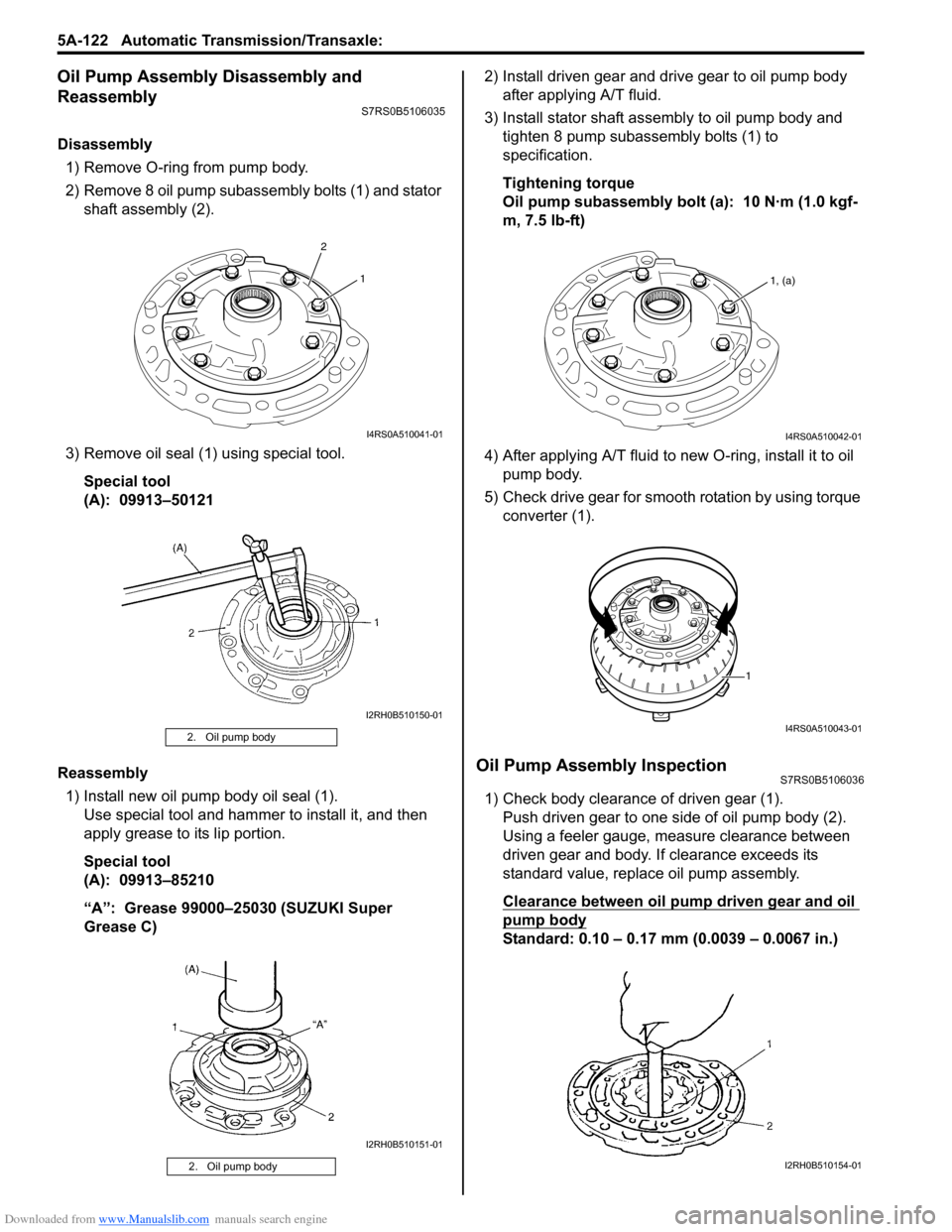
Disassembly1) Remove O-ring from pump body.
2) Remove 8 oil pump subassembly bolts (1) and stator shaft assembly (2).
3) Remove oil seal (1) using special tool. Special tool
(A): 09913–50121
Reassembly 1) Install new oil pump body oil seal (1). Use special tool and hammer to install it, and then
apply grease to its lip portion.
Special tool
(A): 09913–85210
“A”: Grease 99000–25030 (SUZUKI Super
Grease C) 2) Install driven gear and drive gear to oil pump body
after applying A/T fluid.
3) Install stator shaft assembly to oil pump body and tighten 8 pump subassembly bolts (1) to
specification.
Tightening torque
Oil pump subassembly bolt (a): 10 N·m (1.0 kgf-
m, 7.5 lb-ft)
4) After applying A/T fluid to new O-ring, install it to oil pump body.
5) Check drive gear for smooth rotation by using torque converter (1).
Oil Pump Assembly InspectionS7RS0B5106036
1) Check body clearance of driven gear (1).Push driven gear to one side of oil pump body (2).
Using a feeler gauge, m easure clearance between
driven gear and body. If clearance exceeds its
standard value, replace oil pump assembly.
Clearance between oil pump driven gear and oil
pump body
Standard: 0.10 – 0.17 mm (0.0039 – 0.0067 in.)
2. Oil pump body
2. Oil pump body
2 1
I4RS0A510041-01
I2RH0B510150-01
I2RH0B510151-01
1, (a)
I4RS0A510042-01
1
I4RS0A510043-01
I2RH0B510154-01
Page 767 of 1496
Downloaded from www.Manualslib.com manuals search engine Automatic Transmission/Transaxle: 5A-123
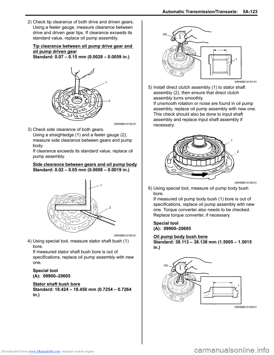
2) Check tip clearance of both drive and driven gears.Using a feeler gauge, m easure clearance between
drive and driven gear tips. If clearance exceeds its
standard value, replace oil pump assembly.
Tip clearance between oil pump drive gear and
oil pump driven gear
Standard: 0.07 – 0.15 mm (0.0028 – 0.0059 in.)
3) Check side clearance of both gears. Using a straightedge (1) and a feeler gauge (2),
measure side clearance between gears and pump
body.
If clearance exceeds its standard value, replace oil
pump assembly.
Side clearance between gears and oil pump body
Standard: 0.02 – 0.05 mm (0.0008 – 0.0019 in.)
4) Using special tool, measure stator shaft bush (1) bore.
If measured stator shaft bush bore is out of
specifications, replace oil pump assembly with new
one.
Special tool
(A): 09900–20605
Stator shaft bush bore
Standard: 18.424 – 18.450 mm (0.7254 – 0.7264
in.) 5) Install direct clutch asse
mbly (1) to stator shaft
assembly (2), then ensure that direct clutch
assembly turns smoothly.
If unsmooth rotation or noise are found in oil pump
assembly, replace oil pump assembly with new one.
This check should also be done to input shaft
assembly and replace input shaft assembly if
necessary.
6) Using special tool, measure oil pump body bush bore.
If measured oil pump body bush (1) bore is out of
specifications, replace o il pump assembly with new
one. Torque converter also needs to be checked.
Replace torque converter, if necessary.
Special tool
(A): 09900–20605
Oil pump body bush bore
Standard: 38.113 – 38.138 mm (1.5005 – 1.5015
in.)
I2RH0B510155-01
I2RH0B510156-01
I2RH0B510157-01
I2RH0B510158-01
I2RH0B510159-01
Page 781 of 1496
Downloaded from www.Manualslib.com manuals search engine Automatic Transmission/Transaxle: 5A-137
Reassembly
Reverse disassembly procedure for assembly, noting the
following points.
• Use new seal rings and O-rings. Apply A/T fluid to seal rings and O-rings before installation.
• Tighten rear cover plugs to specified torque.
Tightening torque
Rear cover plug: 7.5 N·m (0.75 kgf-m, 5.5 lb-ft)
• Before installing rear cover seal ring, apply A/T fluid to ring.
First, tighten seal ring to 5 mm (0.197 in.), then install
seal ring.
• Do not open rear cover seal ring too wide to attach.
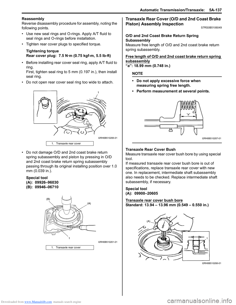
• Do not damage O/D and 2nd coast brake return spring subassembly and piston by pressing in O/D
and 2nd coast brake return spring subassembly
passing through its original installing position over 1.0
mm (0.039 in.).
Special tool
(A): 09926–96030
(B): 09946–06710Transaxle Rear Cover (O/D and 2nd Coast Brake
Piston) Assembly Inspection
S7RS0B5106049
O/D and 2nd Coast Brake Return Spring
Subassembly
Measure free length of O/D and 2nd coast brake return
spring subassembly.
Free length of O/D and 2nd coast brake return spring
subassembly
“a”: 18.99 mm (0.748 in.)
NOTE
• Do not apply excessive force when measuring spring free length.
• Perform measurement at several points.
Transaxle Rear Cover Bush
Measure transaxle rear cover bush bore by using special
tool.
If measured transaxle rear cover bush bore is out of
specifications, replace transaxle rear cover with new
one. In replacement, inte rmediate shaft subassembly
also needs to be checked. Replace intermediate shaft
subassembly, if necessary.
Special tool
(A): 09900–20605
Transaxle rear cover bush bore
Standard: 13.94 – 13.96 mm (0.549 – 0.550 in.)
1. Transaxle rear cover
1. Transaxle rear cover
I2RH0B510206-01
I2RH0B510201-01
I2RH0B510207-01
I2RH0B510208-01
Page 785 of 1496
Downloaded from www.Manualslib.com manuals search engine Automatic Transmission/Transaxle: 5A-141
Reassembly
Reverse disassembly procedure for assembly, noting the
following points.
• Shift solenoid valve-A and -B are identical
• After applying A/T fluid to new O-rings, fit them to solenoid valves, then insta ll solenoid valves to valve
body.
• Tighten solenoid valve bolts to specified torque
Tightening torque
Solenoid valve bolt (a): 11 N·m (1.1 kgf-m, 8.0 lb-ft)
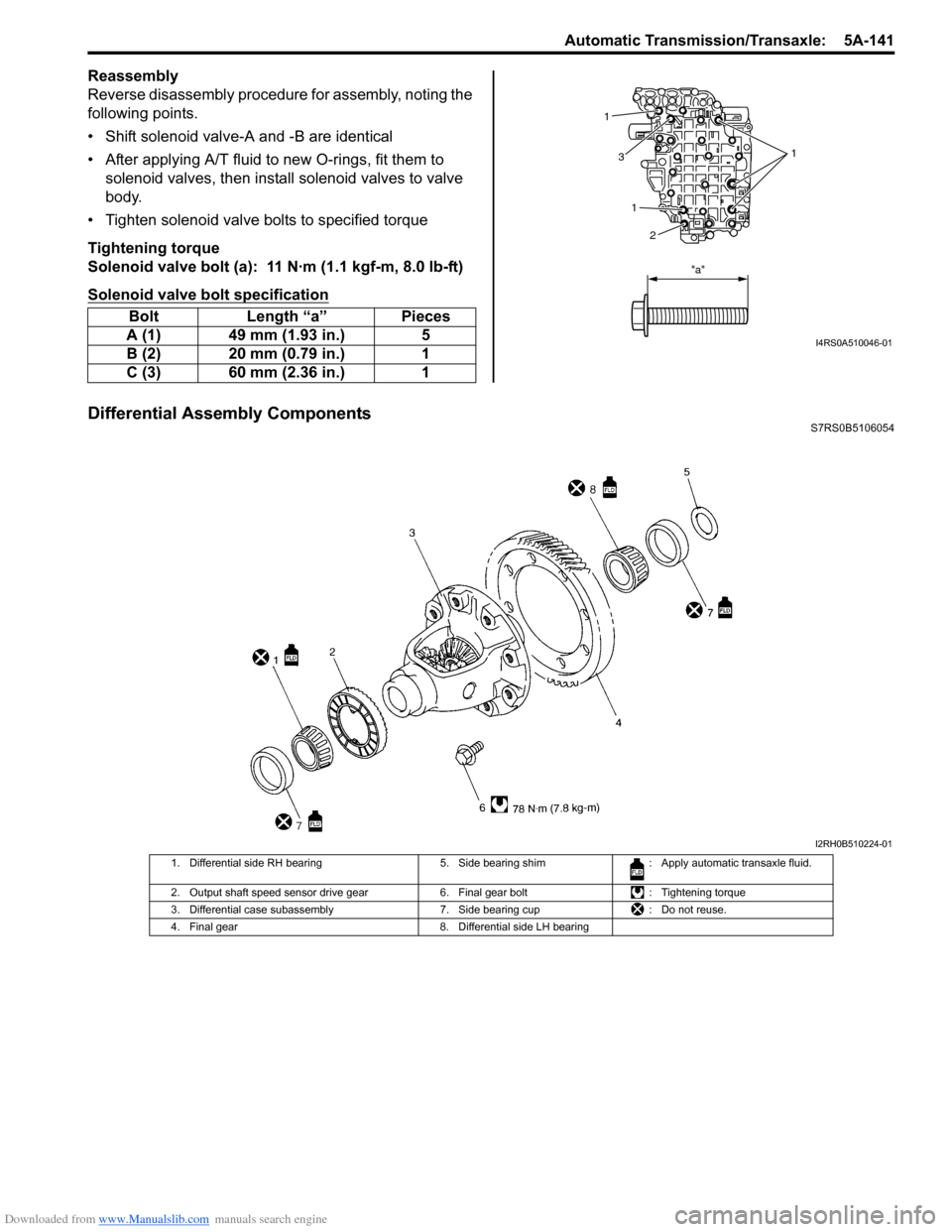
Solenoid valve bolt specification
Differential Assembly ComponentsS7RS0B5106054
Bolt Length “a” Pieces
A (1) 49 mm (1.93 in.) 5
B (2) 20 mm (0.79 in.) 1
C (3) 60 mm (2.36 in.) 1
1
1
1
3
2
"a"
I4RS0A510046-01
I2RH0B510224-01
1. Differential side RH bearing 5. Side bearing shim: Apply automatic transaxle fluid.
2. Output shaft speed sensor drive gear 6. Final gear bolt: Tightening torque
3. Differential case subassembly 7. Side bearing cup: Do not reuse.
4. Final gear 8. Differential side LH bearing
Page 787 of 1496
Downloaded from www.Manualslib.com manuals search engine Automatic Transmission/Transaxle: 5A-143
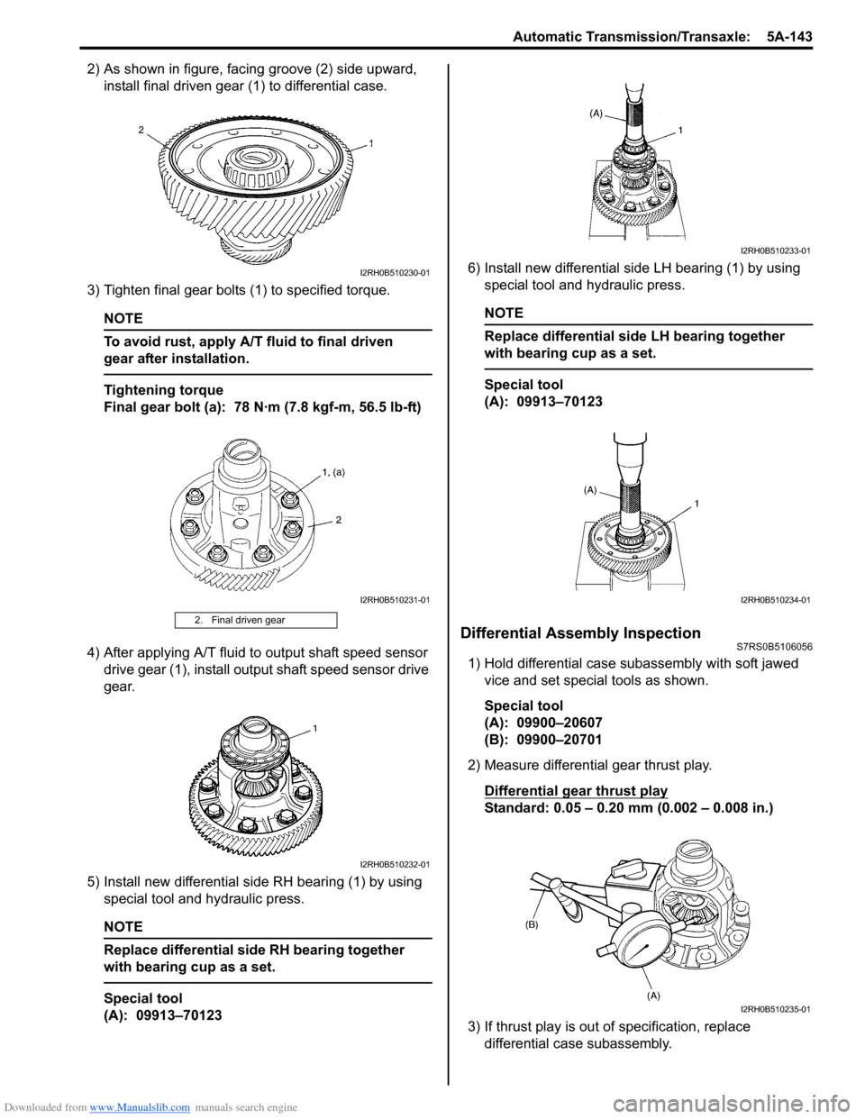
2) As shown in figure, facing groove (2) side upward, install final driven gear (1) to differential case.
3) Tighten final gear bolts (1) to specified torque.
NOTE
To avoid rust, apply A/T fluid to final driven
gear after installation.
Tightening torque
Final gear bolt (a): 78 N·m (7.8 kgf-m, 56.5 lb-ft)
4) After applying A/T fluid to output shaft speed sensor drive gear (1), install output shaft speed sensor drive
gear.
5) Install new differential side RH bearing (1) by using special tool and hydraulic press.
NOTE
Replace differential side RH bearing together
with bearing cup as a set.
Special tool
(A): 09913–70123 6) Install new differential side LH bearing (1) by using
special tool and hydraulic press.
NOTE
Replace differential side LH bearing together
with bearing cup as a set.
Special tool
(A): 09913–70123
Differential Assembly InspectionS7RS0B5106056
1) Hold differential case subassembly with soft jawed
vice and set special tools as shown.
Special tool
(A): 09900–20607
(B): 09900–20701
2) Measure differential gear thrust play.
Differential gear thrust play
Standard: 0.05 – 0.20 mm (0.002 – 0.008 in.)
3) If thrust play is out of specification, replace differential case subassembly.
2. Final driven gear
I2RH0B510230-01
I2RH0B510231-01
I2RH0B510232-01
I2RH0B510233-01
I2RH0B510234-01
I2RH0B510235-01
Page 792 of 1496
Downloaded from www.Manualslib.com manuals search engine 5A-148 Automatic Transmission/Transaxle:
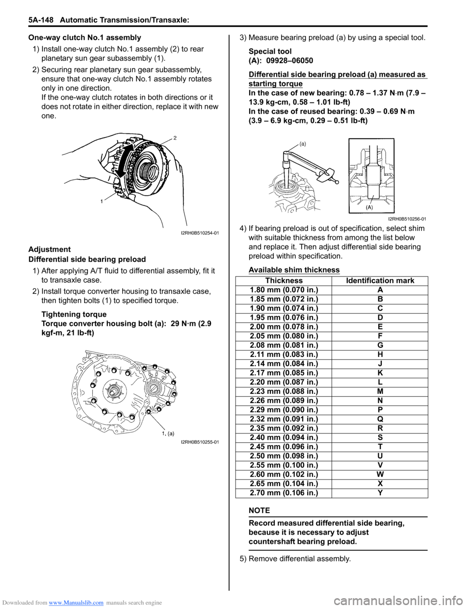
One-way clutch No.1 assembly1) Install one-way clutch No.1 assembly (2) to rear planetary sun gear subassembly (1).
2) Securing rear planetary sun gear subassembly, ensure that one-way clutch No.1 assembly rotates
only in one direction.
If the one-way clutch rotates in both directions or it
does not rotate in either direction, replace it with new
one.
Adjustment
Differential side bearing preload 1) After applying A/T fluid to differential assembly, fit it to transaxle case.
2) Install torque converter housing to transaxle case, then tighten bolts (1) to specified torque.
Tightening torque
Torque converter housing bolt (a): 29 N·m (2.9
kgf-m, 21 lb-ft) 3) Measure bearing preload (a) by using a special tool.
Special tool
(A): 09928–06050
Differential side bearing preload (a) measured as
starting torque
In the case of new bearing: 0.78 – 1.37 N ⋅m (7.9 –
13.9 kg-cm, 0.58 – 1.01 lb-ft)
In the case of reused bearing: 0.39 – 0.69 N ⋅m
(3.9 – 6.9 kg-cm, 0.29 – 0.51 lb-ft)
4) If bearing preload is out of specification, select shim with suitable thickness from among the list below
and replace it. Then adjust differential side bearing
preload within specification.
Available shim thickness
NOTE
Record measured differential side bearing,
because it is necessary to adjust
countershaft bearing preload.
5) Remove differential assembly.
I2RH0B510254-01
I2RH0B510255-01
Thickness Identification mark
1.80 mm (0.070 in.) A
1.85 mm (0.072 in.) B
1.90 mm (0.074 in.) C
1.95 mm (0.076 in.) D
2.00 mm (0.078 in.) E
2.05 mm (0.080 in.) F
2.08 mm (0.081 in.) G
2.11 mm (0.083 in.) H
2.14 mm (0.084 in.) J
2.17 mm (0.085 in.) K
2.20 mm (0.087 in.) L
2.23 mm (0.088 in.) M
2.26 mm (0.089 in.) N
2.29 mm (0.090 in.) P
2.32 mm (0.091 in.) Q
2.35 mm (0.092 in.) R
2.40 mm (0.094 in.) S
2.45 mm (0.096 in.) T
2.50 mm (0.098 in.) U
2.55 mm (0.100 in.) V
2.60 mm (0.102 in.) W
2.65 mm (0.104 in.) X
2.70 mm (0.106 in.) Y
I2RH0B510256-01