bracket SUZUKI SWIFT 2005 2.G Service Manual Online
[x] Cancel search | Manufacturer: SUZUKI, Model Year: 2005, Model line: SWIFT, Model: SUZUKI SWIFT 2005 2.GPages: 1496, PDF Size: 34.44 MB
Page 930 of 1496
Downloaded from www.Manualslib.com manuals search engine 6C-48 Power Assisted Steering System:
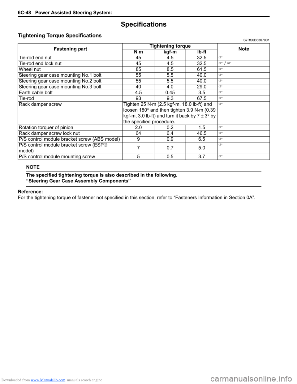
Specifications
Tightening Torque SpecificationsS7RS0B6307001
NOTE
The specified tightening torque is also described in the following.
“Steering Gear Case Assembly Components”
Reference:
For the tightening torque of fastener not specified in this section, refer to “Fasteners Information in Section 0A”.
Fastening part
Tightening torque
Note
N ⋅mkgf-mlb-ft
Tie-rod end nut 454.5 32.5 �)
Tie-rod end lock nut 454.5 32.5 �) / �)
Wheel nut 858.5 61.5 �)
Steering gear case mounting No.1 bolt 555.5 40.0 �)
Steering gear case mounting No.2 bolt 555.5 40.0 �)
Steering gear case mounting No.3 bolt 404.0 29.0 �)
Earth cable bolt 4.5 0.45 3.5�)
Tie-rod 939.3 67.5 �)
Rack damper screw Tighten 25 N⋅m (2.5 kgf-m, 18.0 lb-ft) and
loosen 180 ° and then tighten 3.9 N ⋅m (0.39
kgf-m, 3.0 lb-ft) and turn it back by 7 ± 3° by
the specified procedure. �)
Rotation torquer of pinion 2.00.2 1.5 �)
Rack damper screw lock nut 646.4 46.5 �)
P/S control module bracket screw (ABS model) 9 0.9 6.5�)
P/S control module bracket screw (ESP ®
model) 70
.7 5 .0 �)
P/S control module mounting screw 50.5 3.7 �)
Page 957 of 1496
Downloaded from www.Manualslib.com manuals search engine Air Conditioning System: Manual Type 7B-9
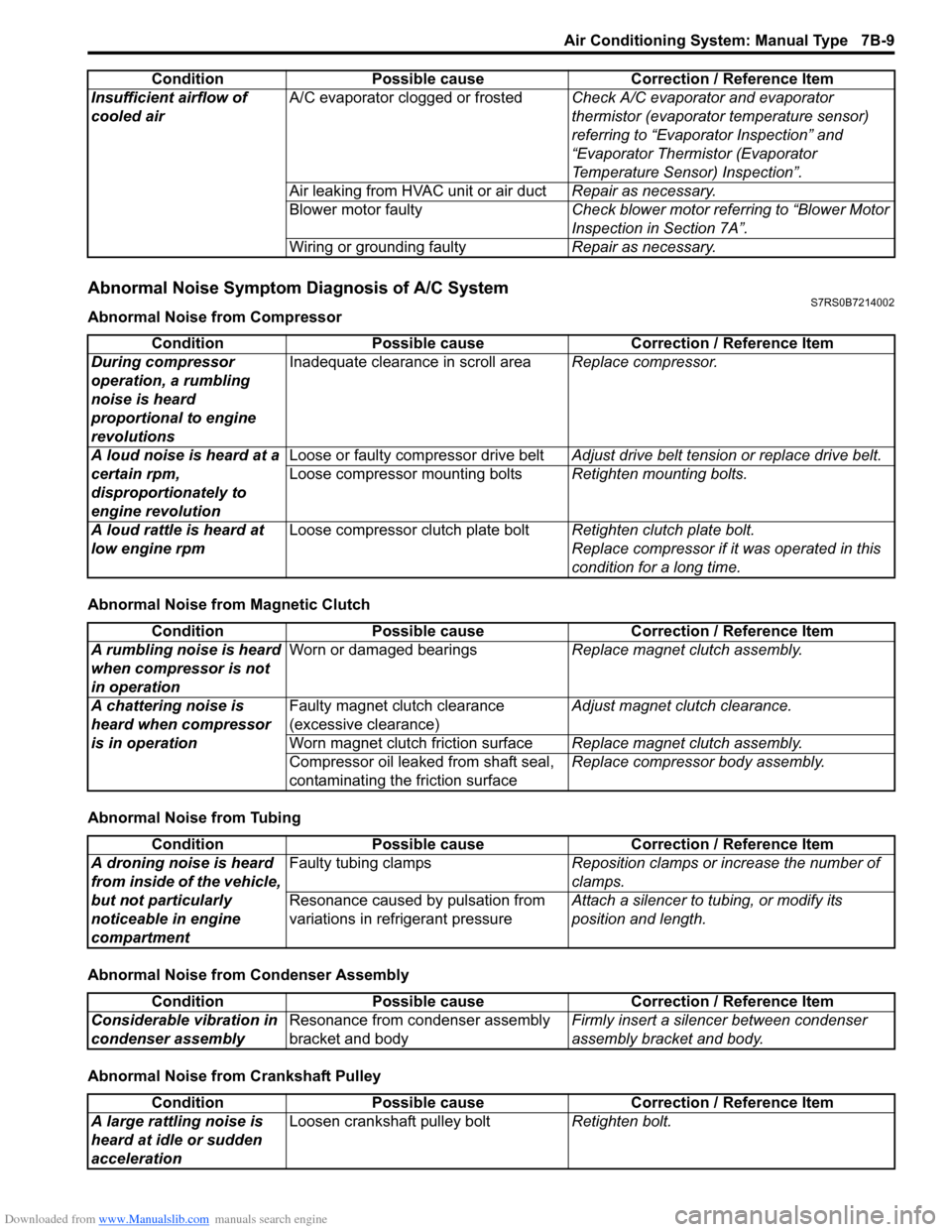
Abnormal Noise Symptom Diagnosis of A/C SystemS7RS0B7214002
Abnormal Noise from Compressor
Abnormal Noise from Magnetic Clutch
Abnormal Noise from Tubing
Abnormal Noise from Condenser Assembly
Abnormal Noise from Crankshaft PulleyInsufficient airflow of
cooled air
A/C evaporator clogged or frosted
Check A/C evaporator and evaporator
thermistor (evaporator temperature sensor)
referring to “Evaporator Inspection” and
“Evaporator Thermistor (Evaporator
Temperature Sensor) Inspection”.
Air leaking from HVAC unit or air duct Repair as necessary.
Blower motor faulty Check blower motor referring to “Blower Motor
Inspection in Section 7A”.
Wiring or grounding faulty Repair as necessary.
Condition Possible cause Correction / Reference Item
Condition
Possible cause Correction / Reference Item
During compressor
operation, a rumbling
noise is heard
proportional to engine
revolutions Inadequate clearance in scroll area
Replace compressor.
A loud noise is heard at a
certain rpm,
disproportionately to
engine revolution Loose or faulty compressor drive belt
Adjust drive belt tension or replace drive belt.
Loose compressor mounting bolts Retighten mounting bolts.
A loud rattle is heard at
low engine rpm Loose compressor clutch plate bolt
Retighten clutch plate bolt.
Replace compressor if it was operated in this
condition for a long time.
Condition Possible cause Correction / Reference Item
A rumbling noise is heard
when compressor is not
in operation Worn or damaged bearings
Replace magnet clutch assembly.
A chattering noise is
heard when compressor
is in operation Faulty magnet clutch clearance
(excessive clearance)
Adjust magnet clutch clearance.
Worn magnet clutch friction surface Replace magnet clutch assembly.
Compressor oil leaked from shaft seal,
contaminating the friction surface Replace compressor body assembly.
Condition
Possible cause Correction / Reference Item
A droning noise is heard
from inside of the vehicle,
but not particularly
noticeable in engine
compartment Faulty tubing clamps
Reposition clamps or increase the number of
clamps.
Resonance caused by pulsation from
variations in re frigerant pressure Attach a silencer to tubing, or modify its
position and length.
Condition
Possible cause Correction / Reference Item
Considerable vibration in
condenser assembly Resonance from condenser assembly
bracket and body Firmly insert a silenc
er between condenser
assembly bracket and body.
Condition Possible cause Correction / Reference Item
A large rattling noise is
heard at idle or sudden
acceleration Loosen crankshaft pulley bolt
Retighten bolt.
Page 958 of 1496

Downloaded from www.Manualslib.com manuals search engine 7B-10 Air Conditioning System: Manual Type
Abnormal Noise from Tension Pulley
Abnormal Noise from A/C Evaporator
Abnormal Noise from Blower Motor
A/C System Performance InspectionS7RS0B7214003
1) Confirm that vehicle and environmental conditions are as follows.
• Vehicle is put indoors.
• Ambient temperature is within 25 – 35 °C (77 – 95
° F).
• Relative humidity is within 30 – 70%.
• There is no wind indoors.
• HVAC unit is normal.
• Blower motor is normal.
• There is no air leakage from air ducts.
• Condenser fins are clean.
• Air filter in HVAC unit is not clogged with dirt and
dust.
• Battery voltage is about 12 V.
• Radiator cooling fan operates normally.
2) Make sure that high pressure valve (1) and low pressure valve (2) of manifold gauge are firmly
closed.
3) Connect high pressure charging hose (3) to high pressure service valve (5) on vehicle and low
pressure charging hose (4) to low pressure service
valve (6).
4) Bleed the air in charging hoses (3) and (4) by loosening their nuts respectively utilizing the
refrigerant pressure. When a hissing sound is heard,
immediately tighten nut.
CAUTION!
Do not connect high and low pressure
charging hoses in reverse.
Condition Possible cause Correction / Reference Item
Clattering noise is heard
from pulley Worn or damaged bearing
Replace tension pulley.
Pulley cranks upon
contact Cracked or loose bracket
Replace or retighten bracket.
ConditionPossible cause Correction / Reference Item
Whistling sound is heard
from A/C evaporator Depending on the combination of the
interior / exterior temperatures, engine
rpm and refrigerant pressure, the
refrigerant flowing out of the expansion
valve may, under certain conditions,
make a whistling sound At times, slightly decrea
sing refrigerant volume
may stop this noise.
Inspect expansion valve and replace if faulty.
Condition Possible cause Correction / Reference Item
Blower motor emits a
chirping sound in
proportion to its speed of
rotation Worn or damaged motor brushes or
commutator
Replace blower motor.
Fluttering noise or large
droning noise is heard
from blower motor Leaves or other debris introduced from
fresh air inlet to blower motor
Remove debris and make sure that the screen
at fresh air inlet is intact.
53
2
1
4 6
I4RS0A720006-01
Page 976 of 1496
Downloaded from www.Manualslib.com manuals search engine 7B-28 Air Conditioning System: Manual Type
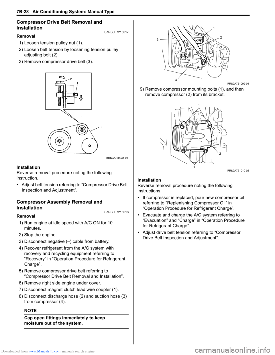
Compressor Drive Belt Removal and
Installation
S7RS0B7216017
Removal1) Loosen tension pulley nut (1).
2) Loosen belt tension by loosening tension pulley adjusting bolt (2).
3) Remove compressor drive belt (3).
Installation
Reverse removal procedure noting the following
instruction.
• Adjust belt tension referring to “Compressor Drive Belt Inspection and Adjustment”.
Compressor Assembly Removal and
Installation
S7RS0B7216018
Removal
1) Run engine at idle speed with A/C ON for 10 minutes.
2) Stop the engine.
3) Disconnect negative (–) cable from battery.
4) Recover refrigerant fr om the A/C system with
recovery and recycling equipment referring to
“Recovery” in “Operation Procedure for Refrigerant
Charge”.
5) Remove compressor drive belt referring to “Compressor Drive Belt Re moval and Installation”.
6) Remove right side engine under cover.
7) Disconnect magnet clutch lead wire coupler (1).
8) Disconnect discharge hose (2) and suction hose (3) from compressor (4).
NOTE
Cap open fittings immediately to keep
moisture out of the system.
9) Remove compressor mounting bolts (1), and then remove compressor (2 ) from its bracket.
Installation
Reverse removal procedure noting the following
instructions.
• If compressor is replaced, pour new compressor oil referring to “Replenishi ng Compressor Oil” in
“Operation Procedure for Refrigerant Charge”.
• Evacuate and charge the A/C system referring to “Evacuation” and “Charge” in “Operation Procedure
for Refrigerant Charge”.
• Adjust drive belt tension referring to “Compressor Drive Belt Inspecti on and Adjustment”.
I4RS0A720034-01
3
4 2
1
I7RS0A721009-01
1
1 2
I7RS0A721010-02
Page 1018 of 1496
Downloaded from www.Manualslib.com manuals search engine 7B-70 Air Conditioning System: Automatic Type
A/C System Performance InspectionS7RS0B7224027
Refer to “A/C System Performance Inspection”.
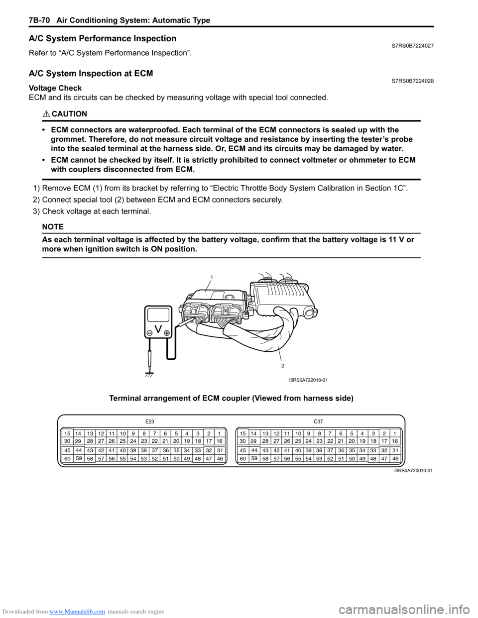
A/C System Inspection at ECMS7RS0B7224028
Voltage Check
ECM and its circuits can be checked by measuring voltage with special tool connected.
CAUTION!
• ECM connectors are waterproofed. Each terminal of the ECM connectors is sealed up with the
grommet. Therefore, do not measure circuit voltage and resistance by inserting the tester’s probe
into the sealed terminal at the harness side. Or, ECM and its circuits may be damaged by water.
• ECM cannot be checked by itself. It is strictly prohibited to connect voltmeter or ohmmeter to ECM with couplers disconnected from ECM.
1) Remove ECM (1) from its bracket by referring to “Electric Throttle Body System Calibration in Section 1C”.
2) Connect special tool (2) between ECM and ECM connectors securely.
3) Check voltage at each terminal.
NOTE
As each terminal voltage is affected by the battery voltage, confirm that the battery voltage is 11 V or
more when ignition sw itch is ON position.
Terminal arrangement of ECM coupler (Viewed from harness side)
1
2
I5RS0A722018-01
E23 C37
34
1819
567
1011
17
20
47 46
495051
2122
52 16
25 9
24
14
29
55
57 54 53
59
60 58 2
262728
15
30
56 4832 31
34353637
40
42 39 38
44
45 43 41 331
1213
238
34
1819
567
1011
17
20
47 46
495051
2122
52 16
25 9
24
14
29
55
57 54 53
59
60 58 2
262728
15
30
56 4832 31
34353637
40
42 39 38
44
45 43 41 331
1213
238
I4RS0A720010-01
Page 1040 of 1496
Downloaded from www.Manualslib.com manuals search engine 8B-2 Air Bag System:
Precautions on Handling and Storage of Air Bag
System Components
S7RS0B8200002
SDM
WARNING!
Never power up air bag system when SDM is
not rigidly attached to the vehicle. Otherwise,
personal injury may result.
CAUTION!
After detecting one time of such collision as
to meet deployment conditions, SDM must
not be used. Refer to “Air Bag Diagnostic
System Check” when checking SDM.
• Never attempt disassembly of SDM.
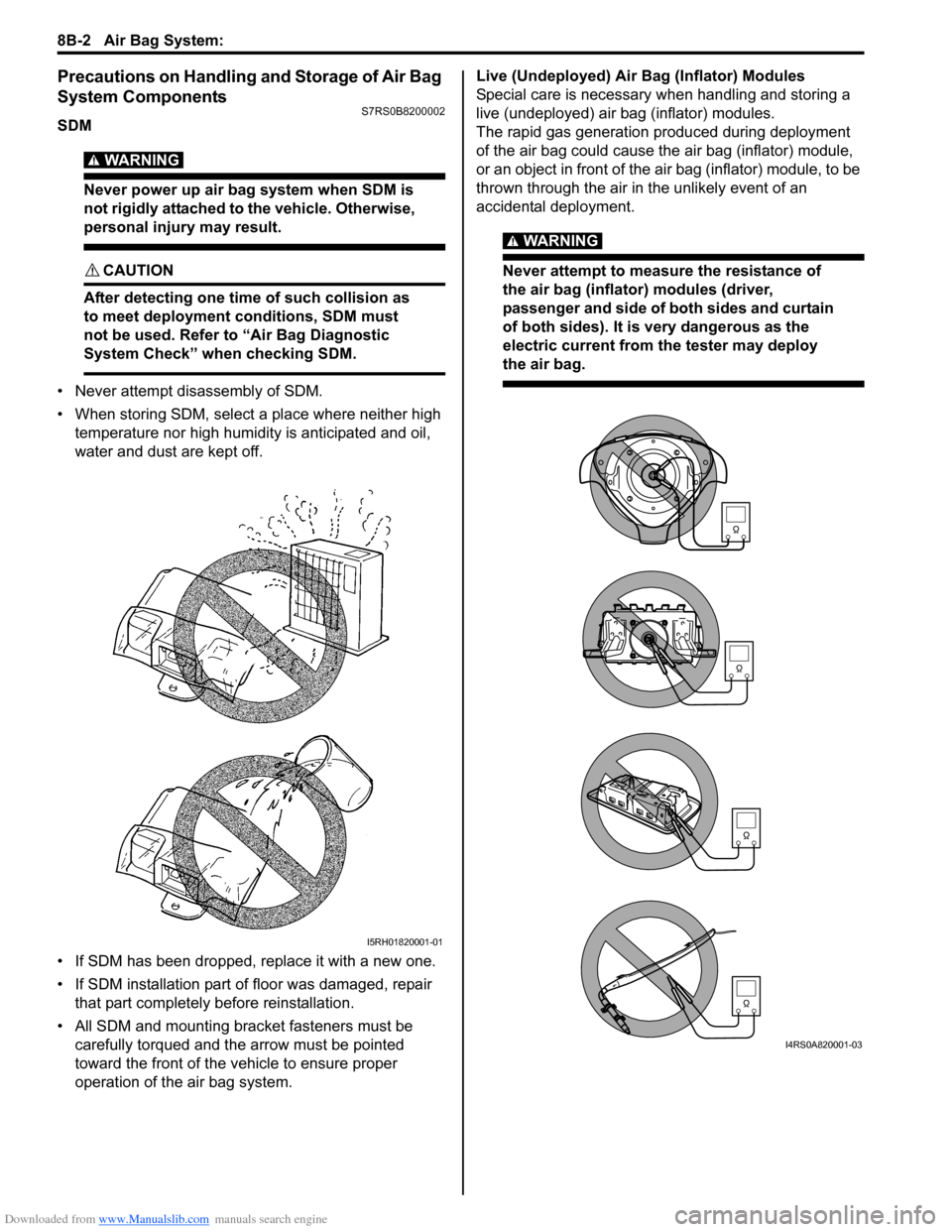
• When storing SDM, select a place where neither high temperature nor high humidity is anticipated and oil,
water and dust are kept off.
• If SDM has been dropped, replace it with a new one.
• If SDM installation part of floor was damaged, repair that part completely before reinstallation.
• All SDM and mounting bracket fasteners must be carefully torqued and the arrow must be pointed
toward the front of the vehicle to ensure proper
operation of the air bag system. Live (Undeployed) Air Bag (Inflator) Modules
Special care is necessary when handling and storing a
live (undeployed) air bag (inflator) modules.
The rapid gas generation produced during deployment
of the air bag could cause the air bag (inflator) module,
or an object in front of the air bag (inflator) module, to be
thrown through the air in the unlikely event of an
accidental deployment.
WARNING!
Never attempt to measure the resistance of
the air bag (inflator) modules (driver,
passenger and side of both sides and curtain
of both sides). It is
very dangerous as the
electric current from the tester may deploy
the air bag.
I5RH01820001-01
I4RS0A820001-03
Page 1041 of 1496
Downloaded from www.Manualslib.com manuals search engine Air Bag System: 8B-3
• Never attempt disassembly of the air bag (inflator) modules.
• If any abnormality is found, be sure to replace it with
new one as an assembly.
• When an abnormality is noted as existing in the live (undeployed) air bag (inflator) module, be sure to
deploy it before discarding it.
• When grease, cleaning agent, oil, water, etc., got on the air bag (inflator) modules (driver, passenger, side
of both sides and curtain of both sides), wipe it off
immediately with a dry cloth.
• If air bag (inflator) module was dropped from a height of 90 cm (3 ft) or more, it should be replaced with a
new one as an assembly.
WARNING!
• For handling and storage of a live air bag (inflator) module, select a place where the
ambient temperature below 65 °C (150 ° F),
without high humidity and away from
electric noise.
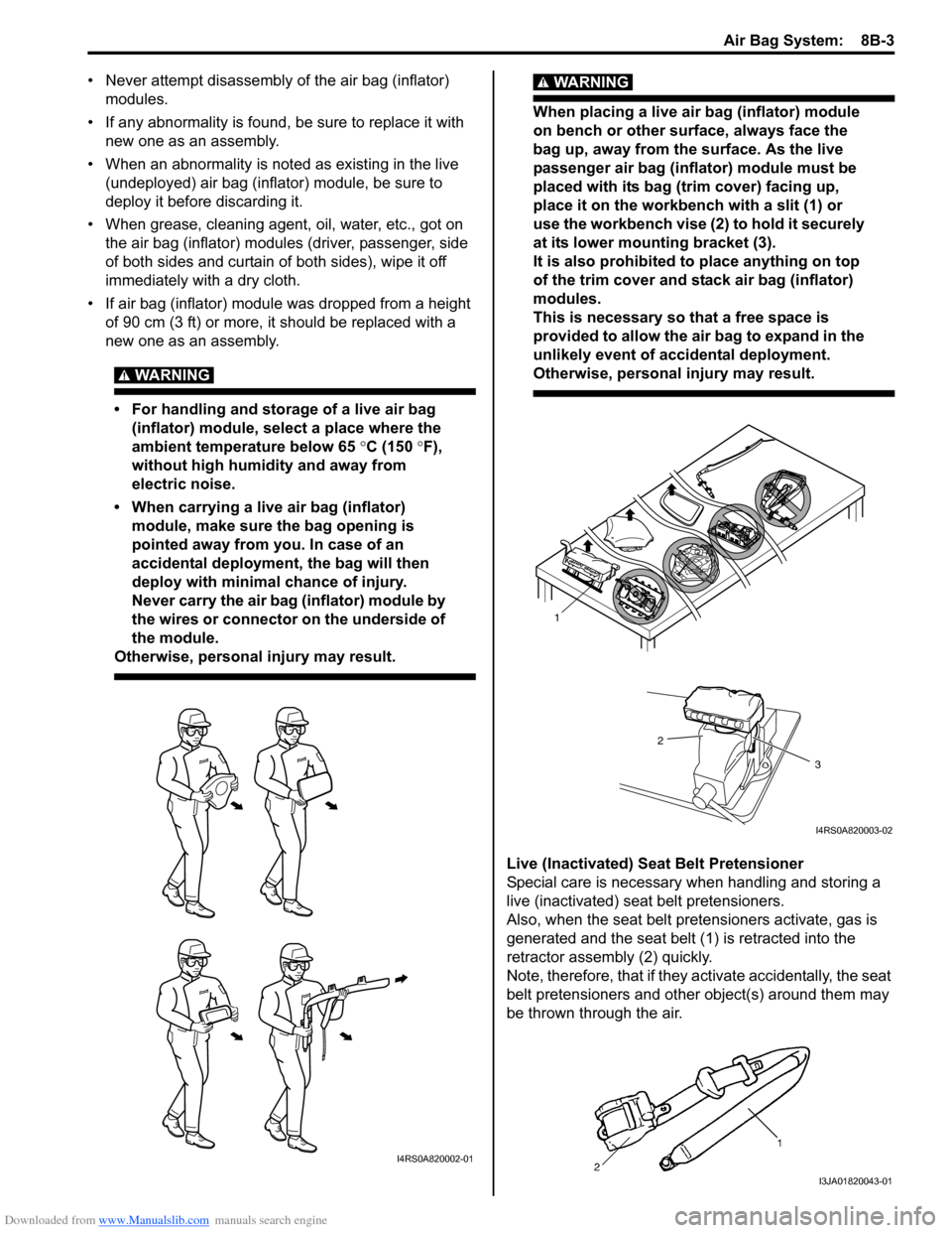
• When carrying a live air bag (inflator) module, make sure the bag opening is
pointed away from you. In case of an
accidental deployment, the bag will then
deploy with minimal chance of injury.
Never carry the air bag (inflator) module by
the wires or connector on the underside of
the module.
Otherwise, personal injury may result.
WARNING!
When placing a live air bag (inflator) module
on bench or other surface, always face the
bag up, away from the surface. As the live
passenger air bag (inflator) module must be
placed with its bag (trim cover) facing up,
place it on the workbench with a slit (1) or
use the workbench vise (2) to hold it securely
at its lower mounting bracket (3).
It is also prohibited to place anything on top
of the trim cover and stack air bag (inflator)
modules.
This is necessary so that a free space is
provided to allow the air bag to expand in the
unlikely event of accidental deployment.
Otherwise, personal injury may result.
Live (Inactivated) Seat Belt Pretensioner
Special care is necessary when handling and storing a
live (inactivated) seat belt pretensioners.
Also, when the seat belt pretensioners activate, gas is
generated and the seat belt (1) is retracted into the
retractor assembly (2) quickly.
Note, therefore, that if they activate accidentally, the seat
belt pretensioners and other object(s) around them may
be thrown through the air.
I4RS0A820002-01
1
2
3
I4RS0A820003-02
I3JA01820043-01
Page 1134 of 1496
Downloaded from www.Manualslib.com manuals search engine 8B-96 Air Bag System:
Repair and Inspection Required after AccidentS7RS0B8204049
CAUTION!
• All air bag system components, including the electrical harness (component
mounting points), must be inspected after
an accident. If any components are
damaged or bent, they must be replaced
even if air bag system activation did not
occur.
• Never use air bag system parts from another vehicle.
• Do not attempt to service the parts below. Service of these parts is by replacement
only.
– Driver / Passenger air bag (inflator) modules
– Driver / Passenger side-air bag (inflator) modules
– Driver / Passenger side curtain-air bag (inflator) modules
– Driver / Passenger seat belt pretensioners
–Forward-sensor
– Driver / Passenger side-sensors
–SDM
– Contact coil and combination switch assembly
– Air bag wire harness in main harness, instrument panel harness and floor
harness.
• Proper operation of the sensors and air bag system requires that any repairs to the
vehicle structure return it to its original
production configuration.
CAUTION!
After detecting one time of such collision as
to meet deployment conditions, the SDM
must not be used.
Refer to “Air Bag Diagnostic System Check”
when checking the SDM.
Accident with Deployment / Activation – Component
Replacement
When driver and passenger air bags are deployed, the
following components must be replaced.
• Driver and passenger air bag (inflator) modules
• Driver and passenger seat belt pretensioners
• SDM after detecting such collision as to meet
deployment conditions
• Forward-sensor
• Instrument panel When side-air bag and side curtain-air bag are deployed,
the following components must be replaced.
• Deployed side-air bag (inflator) module
• Deployed side curtain-air bag (inflator) module
• Side-sensor
•SDM
Accident with or without Deployment / Activation –
Component Inspections
Certain air bag and restraint system components must
be inspected after any crash, whether the air bag system
activated or not. If any faul
ty condition is found in the
following checks, replace faulty part.
Those components are:
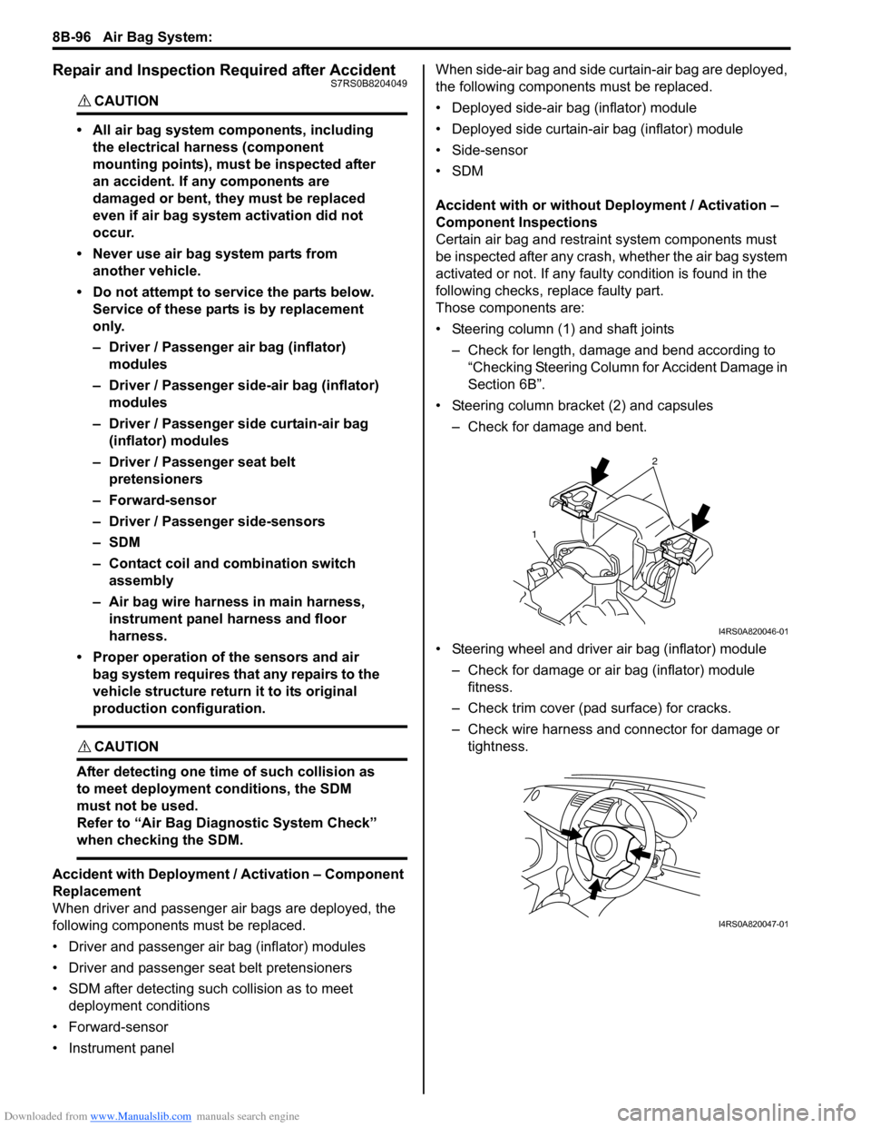
• Steering column (1) and shaft joints
– Check for length, damage and bend according to “Checking Steering Column for Accident Damage in
Section 6B”.
• Steering column bracket (2) and capsules – Check for damage and bent.
• Steering wheel and driver air bag (inflator) module – Check for damage or air bag (inflator) module fitness.
– Check trim cover (pad surface) for cracks.
– Check wire harness and connector for damage or tightness.
2
1
I4RS0A820046-01
I4RS0A820047-01
Page 1141 of 1496
Downloaded from www.Manualslib.com manuals search engine Air Bag System: 8B-103
Driver Air Bag (Inflator) Module InspectionS7RS0B8206006
WARNING!
Never disassemble air bag (inflator) module
or measure its resistance. Otherwise,
personal injury may result.
CAUTION!
If air bag (inflator) module was dropped from
a height of 90 cm (3 ft) or more, it should be
replaced.
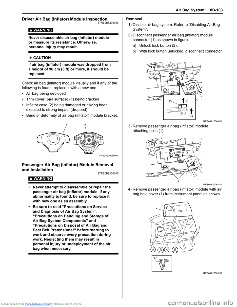
Check air bag (inflator) module visually and if any of the
following is found, replace it with a new one.
• Air bag being deployed
• Trim cover (pad surface) (1) being cracked
• Inflator case (2) being damaged or having been exposed to strong impact (dropped)
• Bend or deformity of air bag (inflator) module bracket.
Passenger Air Bag (Inflator) Module Removal
and Installation
S7RS0B8206007
WARNING!
• Never attempt to disassemble or repair the passenger air bag (inflator) module. If any
abnormality is found, be sure to replace it
with new one as an assembly.
• Be sure to read “Precautions on Service and Diagnosis of Air Bag System”,
“Precautions on Handling and Storage of
Air Bag System Components” and
“Precautions on Disposal of Air Bag and
Seat Belt Pretensioner” before starting to
work and observe every precaution during
work. Neglecting them may result in
personal injury or undeployment of the air
bag when necessary.
Removal
1) Disable air bag system. Re fer to “Disabling Air Bag
System”.
2) Disconnect passenger air bag (inflator) module connector (1) as shown in figure.
a) Unlock lock button (2).
b) With lock button unlocked, disconnect connector.
3) Remove passenger air bag (inflator) module attaching bolts (1).
4) Remove passenger air bag (inflator) module with air bag hole cover (1) from instrument panel as shown.
1 2
I4RS0A820059-01
2
1
a)b)
I4RS0A820060-01
1I4RS0A820061-01
“A”
“A”“A”
1
I4RS0A820062-01
Page 1142 of 1496
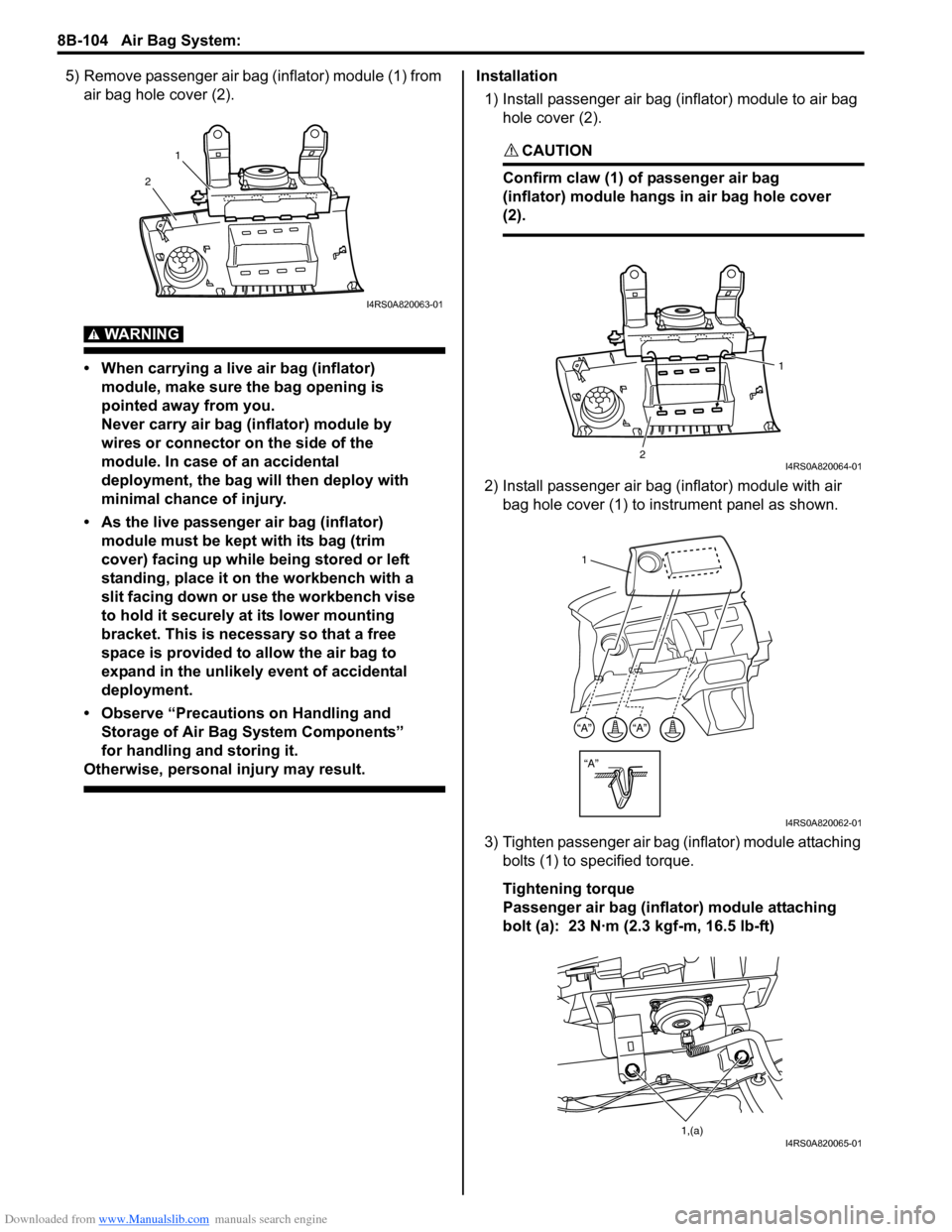
Downloaded from www.Manualslib.com manuals search engine 8B-104 Air Bag System:
5) Remove passenger air bag (inflator) module (1) from air bag hole cover (2).
WARNING!
• When carrying a live air bag (inflator) module, make sure the bag opening is
pointed away from you.
Never carry air bag (inflator) module by
wires or connector on the side of the
module. In case of an accidental
deployment, the bag will then deploy with
minimal chance of injury.
• As the live passenger air bag (inflator) module must be kept with its bag (trim
cover) facing up while being stored or left
standing, place it on the workbench with a
slit facing down or use the workbench vise
to hold it securely at its lower mounting
bracket. This is necessary so that a free
space is provided to allow the air bag to
expand in the unlikely event of accidental
deployment.
• Observe “Precautions on Handling and Storage of Air Bag System Components”
for handling and storing it.
Otherwise, personal injury may result.
Installation
1) Install passenger air bag (inflator) module to air bag hole cover (2).
CAUTION!
Confirm claw (1) of passenger air bag
(inflator) module hangs in air bag hole cover
(2).
2) Install passenger air bag (inflator) module with air bag hole cover (1) to instrument panel as shown.
3) Tighten passenger air bag (inflator) module attaching bolts (1) to sp ecified torque.
Tightening torque
Passenger air bag (inflator) module attaching
bolt (a): 23 N·m (2.3 kgf-m, 16.5 lb-ft)
1
2
I4RS0A820063-01
2 1I4RS0A820064-01
“A”
“A”“A”
1
I4RS0A820062-01
1,(a)I4RS0A820065-01