7B-5 SUZUKI SWIFT 2005 2.G Service Workshop Manual
[x] Cancel search | Manufacturer: SUZUKI, Model Year: 2005, Model line: SWIFT, Model: SUZUKI SWIFT 2005 2.GPages: 1496, PDF Size: 34.44 MB
Page 933 of 1496

Downloaded from www.Manualslib.com manuals search engine Table of Contents 7- i
7
Section 7
CONTENTS
HVAC
Precautions ................................................. 7-1
Precautions............................................................. 7-1
Precautions on HVAC ........................................... 7-1
Heater and Ventilation.... ......................... 7A-1
General Description ............................................. 7A-1
Heater and Ventilation Construction ................... 7A-1
Schematic and Routing Diagram ........................ 7A-2 Heater and Ventilation Wiring Circuit Diagram .... 7A-2
Diagnostic Information and Procedures ............ 7A-3 Heater and Ventilation Symptom Diagnosis........ 7A-3
Repair Instructions .............................................. 7A-4 HVAC Unit Components ..................................... 7A-4
HVAC Unit Removal and Installation .................. 7A-4
Blower Motor Removal and Installation............... 7A-4
Blower Motor Inspection ..................................... 7A-4
Blower Motor Resistor Removal and Installation ......................................................... 7A-5
Blower Motor Resistor Inspection ....................... 7A-5
Blower Motor Relay Inspection ........................... 7A-6
HVAC Control Unit Components ......................... 7A-6
HVAC Control Unit Remova l and Installation ...... 7A-7
Blower Speed Selector In spection ...................... 7A-9
Air Intake Selector Inspec tion ............................. 7A-9
Air Intake Control Actuator Removal and Installation ......................................................... 7A-9
Air Intake Control Actuator Inspection .............. 7A-10
Center Ventilation Louver Removal and Installation ....................................................... 7A-10
Side Ventilation Louver Removal and Installation ....................................................... 7A-11
HVAC Air Filter Removal and Installation (If Equipped)........................................................ 7A-12
HVAC Air Filter Inspection (If Equipped) ........... 7A-12
Air Conditioning System... ...................... 7B-1
Manual Type ............................................................ 7B-1
Precautions........................................................... 7B-1A/C System Caution ............................................ 7B-1
Precautions on Servicing A/C System ................ 7B-1
General Description ............................................. 7B-3 Refrigerant Type Identifica tion ............................ 7B-3
Sub-Cool A/C System Description ...................... 7B-4
A/C Operation Description .................................. 7B-4 Schematic and Routing Diagram ........................7B-5
Major Components of A/C System ...................... 7B-5
A/C System Wiring Diagram ............................... 7B-6
Diagnostic Information and Procedures ............7B-7 A/C System Symptom Diagnosis ........................ 7B-7
Abnormal Noise Sympto m Diagnosis of A/C
System .............................................................. 7B-9
A/C System Performance Inspection ................ 7B-10
A/C System Inspection at ECM ......................... 7B-15
Repair Instructions ........... .................................7B-16
Operation Procedure for Re frigerant Charge .... 7B-16
Condenser Assembly On-Vehicle Inspection .... 7B-21
Condenser Assembly Removal and Installation ....................................................... 7B-21
Receiver/Dryer Removal and Installation .......... 7B-22
HVAC Unit Components ................................... 7B-23
HVAC Unit Removal and In stallation ................ 7B-24
Evaporator Inspection ....................................... 7B-24
Evaporator Thermistor (Evaporator Temperature Sensor) Removal and
Installation ....................................................... 7B-25
Evaporator Thermistor (Evaporator Temperature Sensor) Inspec tion..................... 7B-25
Expansion Valve Removal and Installation ....... 7B-26
Expansion Valve Inspection .............................. 7B-26
A/C Refrigerant Pressure Sensor and Its Circuit Inspection............................................. 7B-26
A/C Refrigerant Pressu re Sensor Removal
and Installation ................................................ 7B-26
A/C Switch Inspection ....................................... 7B-27
Compressor Relay Inspection ........................... 7B-27
Compressor Drive Belt Inspection and Adjustment ...................................................... 7B-27
Compressor Drive Belt Removal and Installation ....................................................... 7B-28
Compressor Assembly Removal and Installation ....................................................... 7B-28
Compressor Assembly Components................. 7B-29
Magnet Clutch Inspection.................................. 7B-29
Magnet Clutch Removal and Installation........... 7B-29
Relief Valve Inspection...................................... 7B-31
Relief Valve Removal and Installation............... 7B-32
Specifications .................... .................................7B-32
Tightening Torque Specifications ...................... 7B-32
Special Tools and Equipmen t ...........................7B-33
Page 934 of 1496

Downloaded from www.Manualslib.com manuals search engine 7-ii Table of Contents
Recommended Service Material ....................... 7B-33
Special Tool ...................................................... 7B-33
Automatic Type .................... .................................7B-34
Precautions.........................................................7B-34 A/C System Caution .......................................... 7B-34
Precautions in Diagnosing Trouble ................... 7B-34
Precautions on Servicing A/C System .............. 7B-34
General Description .......... .................................7B-34
Auto A/C System Descript ion ............................ 7B-34
HVAC Control Module Operation Description ... 7B-36
Refrigerant Type Identifica tion .......................... 7B-36
Sub-Cool A/C System Description .................... 7B-36
A/C Operation Description ................................ 7B-36
On-Board Diagnostic System Description ......... 7B-37
Schematic and Routing Diagram ......................7B-37 Major Components of A/C System .................... 7B-37
A/C System Wiring Diagra m ............................. 7B-38
Diagnostic Information and Procedures ..........7B-39 A/C System Symptom Diagnosis ...................... 7B-39
Abnormal Noise Sympto m Diagnosis of A/C
System ............................................................ 7B-42
DTC Check........................................................ 7B-42
DTC Clearance ................................................. 7B-43
DTC Table ......................................................... 7B-44
Fail-Safe Table ................. ................................. 7B-45
Scan Tool Data ................................................. 7B-46
Air Conditioning System Check......................... 7B-47
Visual Inspection ............................................... 7B-49
DTC B1502: Inside Air Temperature Sensor and/or Its Circuit Malfunction .......................... 7B-49
DTC B1503: A/C Evaporator Air Temperature Sensor and/or Its Circuit Malfunction .............. 7B-50
DTC B1504: Sunload Sensor and/or Its Circuit Malfunction ......... ................................. 7B-52
DTC B1511: Temperature Control Actuator (Position Sensor) and/or Its Circuit
Malfunction ...................................................... 7B-53
DTC B1512: Air flow Control Actuator (Position Sensor) and/or Its Circuit
Malfunction ...................................................... 7B-55
DTC B1513: Temperature Control Actuator and/or Its Circuit Malfunction .......................... 7B-57
DTC B1514: Air Flow Co ntrol Actuator and/or
Its Circuit Malfunction ...................................... 7B-60
DTC B1541: HVAC Control Module Back-Up Power Supply Malfunction .............................. 7B-62
DTC B1546: A/C Refrigerant Pressure Malfunction ...................................................... 7B-63
DTC B1551: Serial Communication Circuit Malfunction ...................................................... 7B-63
DTC B1552: Serial Communication Signal Malfunction ...................................................... 7B-64
DTC B1553: CAN Communication Signal Malfunction ...................................................... 7B-65
DTC B1557: Vehicle Speed Sensor Signal Malfunction ...................................................... 7B-65
DTC B1561: Engine Coolant Temperature Sensor Signal Malfunctio n .............................. 7B-66 DTC B1562: Outside Air Temperature Sensor
Signal Malfunction ........................................... 7B-66
DTC B1563: A/C Refr igerant Pressure
Sensor Signal Malfunction .............................. 7B-66
Inspection of HVAC Control Module and Its Circuit .............................................................. 7B-67
A/C System Performance Inspection ................ 7B-70
A/C System Inspection at ECM ......................... 7B-70
Repair Instructions ............ ................................7B-71
Operation Procedure for Refrigerant Charge .... 7B-71
HVAC Unit Components ................................... 7B-72
HVAC Unit Removal and In stallation ................ 7B-73
Temperature Control Actuator Removal and Installation ....................................................... 7B-73
Temperature Control Actuat or Inspection ......... 7B-73
Air Flow Control Actuator Removal and Installation ....................................................... 7B-74
Air Flow Control Actuator Inspection ................. 7B-74
Air Intake Control Actuator Removal and Installation ....................................................... 7B-75
Air Intake Control Actuator Inspection............... 7B-75
Actuator Linkage Inspection .............................. 7B-76
Blower Motor Controller Removal and Installation ....................................................... 7B-76
Blower Motor Controller Inspection ................... 7B-76
HVAC Control Module Removal and Installation ....................................................... 7B-77
Sunload Sensor Removal and Installation ........ 7B-77
Sunload Sensor Inspection ............................... 7B-77
Outside Air Temperature Sensor Removal and Installation ................................................ 7B-77
Outside Air Temperature Sensor Inspection ..... 7B-77
Inside Air Temperature Sensor Removal and Installation ....................................................... 7B-78
Inside Air Temperature Sens or Inspection ........ 7B-78
Condenser Assembly On-Vehicle Inspection .... 7B-78
Condenser Assembly Removal and Installation ....................................................... 7B-78
Receiver/Dryer Removal and Installation .......... 7B-78
Evaporator Inspection ....................................... 7B-78
Evaporator Temperature Sensor Removal and Installation ................................................ 7B-78
Evaporator Temperature Se nsor Inspection ..... 7B-78
Expansion Valve Removal an d Installation ....... 7B-78
Expansion Valve Inspection .............................. 7B-78
A/C Refrigerant Pressure Sensor and Its Circuit Inspection............................................. 7B-78
A/C Refrigerant Pressu re Sensor Removal
and Installation ................................................ 7B-78
Compressor Relay Inspection .
.......................... 7B-78
Compressor Drive Belt Inspection and Adjustment ...................................................... 7B-78
Compressor Drive Belt Removal and Installation ....................................................... 7B-79
Compressor Assembly Removal and Installation ....................................................... 7B-79
Compressor Assembly Components................. 7B-79
Magnet Clutch Removal and Installation........... 7B-79
Magnet Clutch Inspection.................................. 7B-79
Relief Valve Inspection...................................... 7B-79
Page 953 of 1496
Downloaded from www.Manualslib.com manuals search engine Air Conditioning System: Manual Type 7B-5
Schematic and Routing Diagram
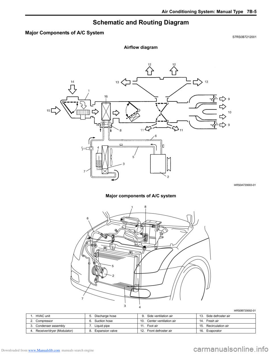
Major Components of A/C SystemS7RS0B7212001
Airflow diagram
Major components of A/C system
I4RS0A720003-01
7
2
34
1 8
6
5
I4RS0B720002-01
1. HVAC unit 5. Discharge hose9. Side ventilation air 13. Side defroster air
2. Compressor 6. Suction hose10. Center ventilation air 14. Fresh air
3. Condenser assembly 7. Liquid pipe11. Foot air 15. Recirculation air
4. Receiver/dryer (Modulator) 8. Expansion valve12. Front defroster air 16. Evaporator
Page 998 of 1496
Downloaded from www.Manualslib.com manuals search engine 7B-50 Air Conditioning System: Automatic Type
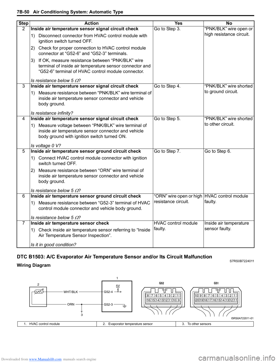
DTC B1503: A/C Evaporator Air Temperature Sensor and/or Its Circuit MalfunctionS7RS0B7224011
Wiring Diagram2
Inside air temperature sensor signal circuit check
1) Disconnect connector from HVAC control module with
ignition switch turned OFF.
2) Check for proper connection to HVAC control module connector at “G52-6” and “G52-3” terminals.
3) If OK, measure resistance between “PNK/BLK” wire terminal of inside air temp erature sensor connector and
“G52-6” terminal of HVAC control module connector.
Is resistance below 5
Ω? Go to Step 3. “PNK/BLK” wire open or
high resistance circuit.
3 Inside air temperature sensor signal circuit check
1) Measure resistance between “PNK/BLK” wire terminal of
inside air temperature sensor connector and vehicle
body ground.
Is resistance infinity? Go to Step 4.
“PNK/BLK” wire shorted
to ground circuit.
4 Inside air temperature sensor signal circuit check
1) Measure voltage between “PNK/BLK” wire terminal of
inside air temperature sensor connector and vehicle
body ground with ignition switch turned ON.
Is voltage 0 V? Go to Step 5.
“PNK/BLK” wire shorted
to other circuit.
5 Inside air temperature sensor ground circuit check
1) Connect HVAC control module connector with ignition
switch turned OFF.
2) Measure resistance between “ORN” wire terminal of inside air temperature sensor connector and vehicle
body ground.
Is resistance below 5
Ω? Go to Step 7. Go to Step 6.
6 Inside air temperature sensor ground circuit check
1) Measure resistance between “G52-3” terminal of HVAC
control module connector and vehicle body ground.
Is resistance below 5
Ω? “ORN” wire open or high
resistance circuit.
HVAC control module
faulty.
7 Inside air temperature sensor check
1) Check inside air temperature sensor referring to “Inside
Air Temperature Sensor Inspection”.
Is it in good condition? HVAC control module
faulty.
Inside air temperature
sensor faulty.
Step Action Yes No
5V
WHT/BLK
ORN G52-4
G52-3
2
1
3
7812910
65 431516 14 13 12 11
G52
789101920121112
65 431718 16 15 14 13
G51
I5RS0A722011-01
1. HVAC control module
2. Evaporator temperature sensor 3. To other sensors
Page 999 of 1496
Downloaded from www.Manualslib.com manuals search engine Air Conditioning System: Automatic Type 7B-51
DTC Detecting Condition and Trouble Area
DTC Troubleshooting
NOTE
When DTC B1502, B1513 and B1514 are indicated together, it is possible that “ORN” wire circuit open.
DTC Detecting ConditionTrouble Area
Evaporator temperature sensor signal voltage is higher than or lower than
specified value for specified time continuously. • Evaporator temperature sensor
circuit
• Evaporator temperature sensor
• HVAC control module
Step Action YesNo
1 Evaporator temperature sensor signal circuit check
1) Disconnect evaporator temperature sensor connector.
2) Check for proper connection to evaporator temperature
sensor at “WHT/BLK” and “ORN” wire terminals.
3) If OK, measure voltage between “WHT/BLK” wire terminal of evaporator te mperature sensor connector
and vehicle body ground with ignition switch turned ON.
Is voltage 4 – 6 V? Go to Step 5.
Go to Step 2.
2 Evaporator temperature sensor signal circuit check
1) Disconnect connector from HVAC control module with
ignition switch turned OFF.
2) Check for proper connection to HVAC control module connector at “G52-4” and “G52-3” terminals.
3) If OK, measure resistance between “WHT/BLK” wire terminal of evaporator te mperature sensor connector
and “G52-4” terminal of HVAC control module connector.
Is resistance below 5
Ω? Go to Step 3. “WHT/BLK” wire open
or high resistance
circuit.
3 Evaporator temperature sensor signal circuit check
1) Measure resistance between “WHT/BLK” wire terminal
of evaporator temperature sensor connector and vehicle
body ground.
Is resistance infinity? Go to Step 4. “WHT/BLK” wire
shorted to ground
circuit.
4 Evaporator temperature sensor signal circuit check
1) Measure voltage between “WHT/BLK” wire terminal of
evaporator temperature sens or connector and vehicle
body ground with ignition switch turned ON.
Is voltage 0 V? Go to Step 5. “WHT/BLK” wire
shorted to other circuit.
5 Evaporator temperature sensor ground circuit check
1) Connect HVAC control module connector with ignition
switch turned OFF.
2) Measure resistance between “ORN” wire terminal of evaporator temperature sens or connector and vehicle
body ground.
Is resistance below 5
Ω? Go to Step 7. Go to Step 6.
6 Evaporator temperature sensor ground circuit check
1) Measure resistance between “G52-3” terminal of HVAC
control module connector and vehicle body ground.
Is resistance below 5
Ω? “ORN” wire open or high
resistance circuit.
HVAC control module
faulty.
Page 1000 of 1496
Downloaded from www.Manualslib.com manuals search engine 7B-52 Air Conditioning System: Automatic Type
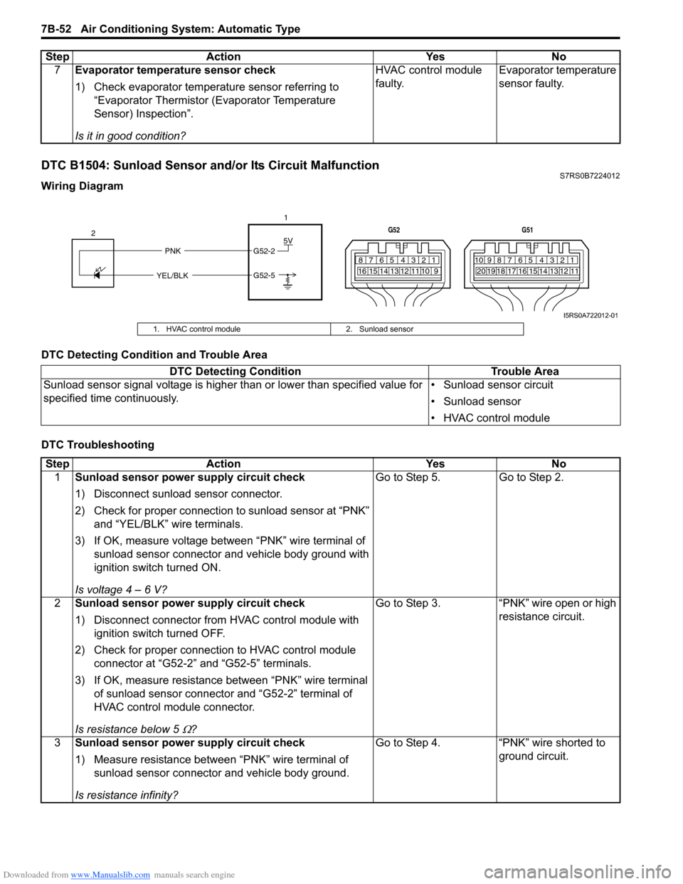
DTC B1504: Sunload Sensor and/or Its Circuit MalfunctionS7RS0B7224012
Wiring Diagram
DTC Detecting Condition and Trouble Area
DTC Troubleshooting7
Evaporator temperature sensor check
1) Check evaporator temperature sensor referring to
“Evaporator Thermistor (Evaporator Temperature
Sensor) Inspection”.
Is it in good condition? HVAC control module
faulty.
Evaporator temperature
sensor faulty.
Step Action Yes No
5V
PNK G52-2
G52-5
YEL/BLK
2
1
7812910
65 431516 14 13 12 11
G52
789101920121112
65 431718 16 15 14 13
G51
I5RS0A722012-01
1. HVAC control module
2. Sunload sensor
DTC Detecting Condition Trouble Area
Sunload sensor signal voltage is higher than or lower than specified value for
specified time continuously. • Sunload sensor circuit
• Sunload sensor
• HVAC control module
Step
Action YesNo
1 Sunload sensor power supply circuit check
1) Disconnect sunload sensor connector.
2) Check for proper connection to sunload sensor at “PNK”
and “YEL/BLK” wire terminals.
3) If OK, measure voltage between “PNK” wire terminal of sunload sensor connector and vehicle body ground with
ignition switch turned ON.
Is voltage 4 – 6 V? Go to Step 5.
Go to Step 2.
2 Sunload sensor power supply circuit check
1) Disconnect connector from HVAC control module with
ignition switch turned OFF.
2) Check for proper connection to HVAC control module connector at “G52-2” and “G52-5” terminals.
3) If OK, measure resistance between “PNK” wire terminal of sunload sensor connector and “G52-2” terminal of
HVAC control module connector.
Is resistance below 5
Ω? Go to Step 3. “PNK” wire open or high
resistance circuit.
3 Sunload sensor power supply circuit check
1) Measure resistance between “PNK” wire terminal of
sunload sensor connector and vehicle body ground.
Is resistance infinity? Go to Step 4. “PNK” wire shorted to
ground circuit.
Page 1001 of 1496
Downloaded from www.Manualslib.com manuals search engine Air Conditioning System: Automatic Type 7B-53
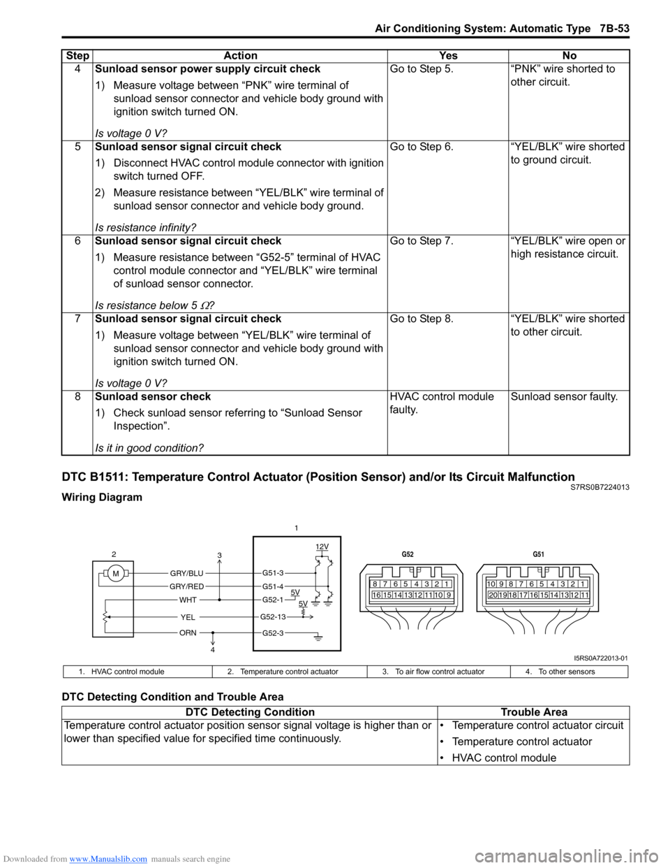
DTC B1511: Temperature Control Actuator (Position Sensor) and/or Its Circuit MalfunctionS7RS0B7224013
Wiring Diagram
DTC Detecting Condition and Trouble Area4
Sunload sensor power supply circuit check
1) Measure voltage between “PNK” wire terminal of
sunload sensor connector and vehicle body ground with
ignition switch turned ON.
Is voltage 0 V? Go to Step 5. “PNK” wire shorted to
other circuit.
5 Sunload sensor signal circuit check
1) Disconnect HVAC control modul e connector with ignition
switch turned OFF.
2) Measure resistance between “YEL/BLK” wire terminal of sunload sensor connector and vehicle body ground.
Is resistance infinity? Go to Step 6. “YEL/BLK” wire shorted
to ground circuit.
6 Sunload sensor signal circuit check
1) Measure resistance between “G52-5” terminal of HVAC
control module connector and “YEL/BLK” wire terminal
of sunload sensor connector.
Is resistance below 5
Ω? Go to Step 7. “YEL/BLK” wire open or
high resistance circuit.
7 Sunload sensor signal circuit check
1) Measure voltage between “YEL/BLK” wire terminal of
sunload sensor connector and vehicle body ground with
ignition switch turned ON.
Is voltage 0 V? Go to Step 8.
“YEL/BLK” wire shorted
to other circuit.
8 Sunload sensor check
1) Check sunload sensor referring to “Sunload Sensor
Inspection”.
Is it in good condition? HVAC control module
faulty.
Sunload sensor faulty.
Step
Action YesNo
7812910
65 431516 14 13 12 11
G52
789101920121112
65 431718 16 15 14 13
G51
M 12V
5V 5V
YEL
WHT
GRY/BLU
GRY/RED
2
1
ORN
G51-3
G51-4
G52-1
G52-13
G52-3
3
4
I5RS0A722013-01
1. HVAC control module 2. Temperature control actuator 3. To air flow control actuator4. To other sensors
DTC Detecting Condition Trouble Area
Temperature control actuator position sensor signal voltage is higher than or
lower than specified value for specified time continuously. • Temperature control actuator circuit
• Temperature control actuator
• HVAC control module
Page 1002 of 1496
Downloaded from www.Manualslib.com manuals search engine 7B-54 Air Conditioning System: Automatic Type
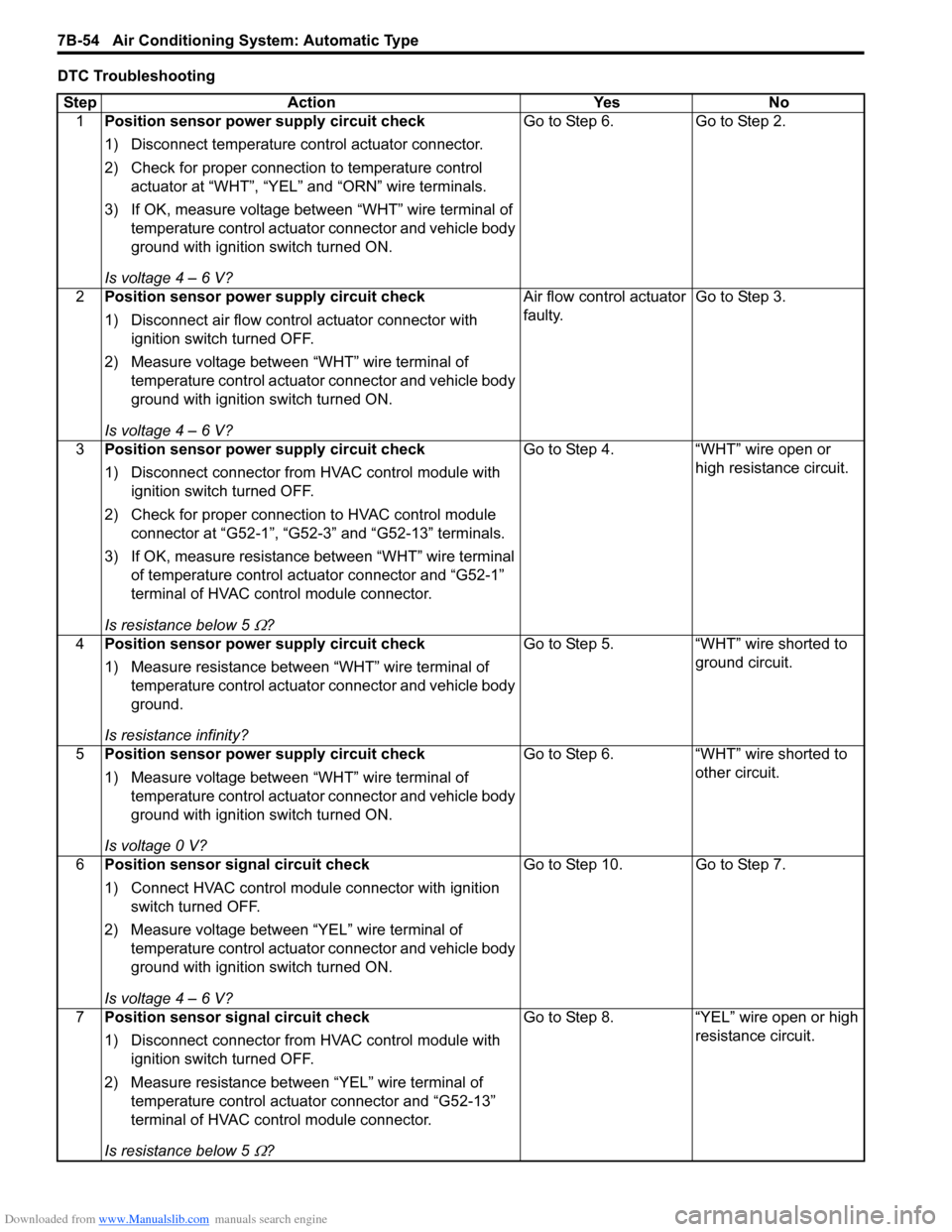
DTC TroubleshootingStep Action YesNo
1 Position sensor power supply circuit check
1) Disconnect temperature control actuator connector.
2) Check for proper connection to temperature control
actuator at “WHT”, “YEL” and “ORN” wire terminals.
3) If OK, measure voltage between “WHT” wire terminal of temperature control actuator connector and vehicle body
ground with ignition switch turned ON.
Is voltage 4 – 6 V? Go to Step 6.
Go to Step 2.
2 Position sensor power supply circuit check
1) Disconnect air flow control actuator connector with
ignition switch turned OFF.
2) Measure voltage between “WHT” wire terminal of temperature control actuator connector and vehicle body
ground with ignition switch turned ON.
Is voltage 4 – 6 V? Air flow control actuator
faulty.
Go to Step 3.
3 Position sensor power supply circuit check
1) Disconnect connector from HVAC control module with
ignition switch turned OFF.
2) Check for proper connection to HVAC control module connector at “G52-1”, “G52-3” and “G52-13” terminals.
3) If OK, measure resistance between “WHT” wire terminal of temperature control actuator connector and “G52-1”
terminal of HVAC control module connector.
Is resistance below 5
Ω? Go to Step 4. “WHT” wire open or
high resistance circuit.
4 Position sensor power supply circuit check
1) Measure resistance between “WHT” wire terminal of
temperature control actuator connector and vehicle body
ground.
Is resistance infinity? Go to Step 5.
“WHT” wire shorted to
ground circuit.
5 Position sensor power supply circuit check
1) Measure voltage between “WHT” wire terminal of
temperature control actuator connector and vehicle body
ground with ignition switch turned ON.
Is voltage 0 V? Go to Step 6.
“WHT” wire shorted to
other circuit.
6 Position sensor signal circuit check
1) Connect HVAC control module connector with ignition
switch turned OFF.
2) Measure voltage between “YEL” wire terminal of temperature control actuator connector and vehicle body
ground with ignition switch turned ON.
Is voltage 4 – 6 V? Go to Step 10. Go to Step 7.
7 Position sensor signal circuit check
1) Disconnect connector from HVAC control module with
ignition switch turned OFF.
2) Measure resistance between “YEL” wire terminal of temperature control actuator connector and “G52-13”
terminal of HVAC control module connector.
Is resistance below 5
Ω? Go to Step 8. “YEL” wire open or high
resistance circuit.
Page 1003 of 1496
Downloaded from www.Manualslib.com manuals search engine Air Conditioning System: Automatic Type 7B-55
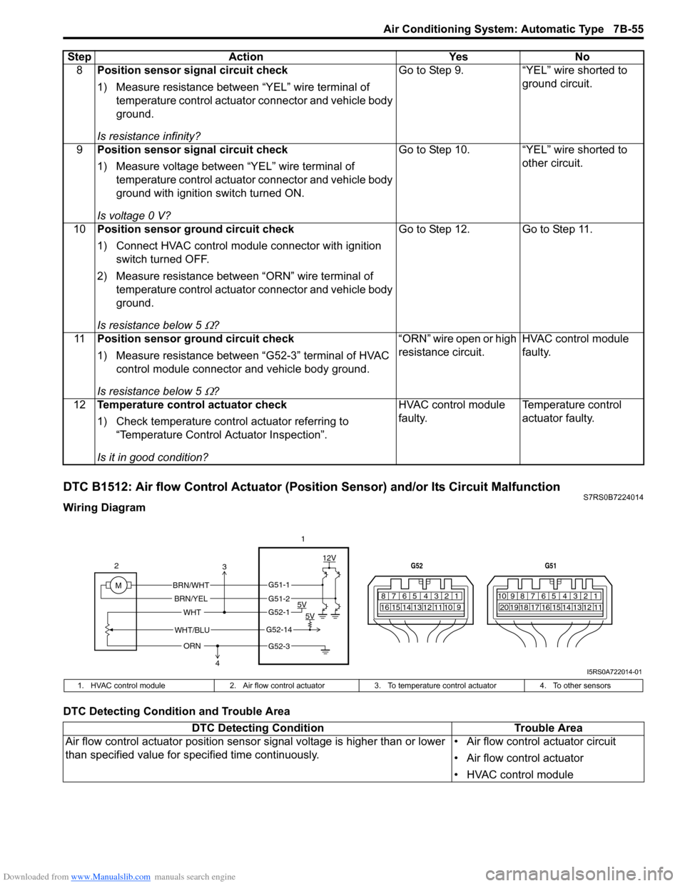
DTC B1512: Air flow Control Actuator (Position Sensor) and/or Its Circuit MalfunctionS7RS0B7224014
Wiring Diagram
DTC Detecting Condition and Trouble Area8
Position sensor signal circuit check
1) Measure resistance between “YEL” wire terminal of
temperature control actuator connector and vehicle body
ground.
Is resistance infinity? Go to Step 9. “YEL” wire shorted to
ground circuit.
9 Position sensor signal circuit check
1) Measure voltage between “YEL” wire terminal of
temperature control actuator connector and vehicle body
ground with ignition switch turned ON.
Is voltage 0 V? Go to Step 10. “YEL” wire shorted to
other circuit.
10 Position sensor ground circuit check
1) Connect HVAC control module connector with ignition
switch turned OFF.
2) Measure resistance between “ORN” wire terminal of temperature control actuator connector and vehicle body
ground.
Is resistance below 5
Ω? Go to Step 12. Go to Step 11.
11 Position sensor ground circuit check
1) Measure resistance between “G52-3” terminal of HVAC
control module connector and vehicle body ground.
Is resistance below 5
Ω? “ORN” wire open or high
resistance circuit.
HVAC control module
faulty.
12 Temperature control actuator check
1) Check temperature control actuator referring to
“Temperature Control Actuator Inspection”.
Is it in good condition? HVAC control module
faulty.
Temperature control
actuator faulty.
Step Action Yes No
7812910
65 431516 14 13 12 11
G52
789101920121112
65 431718 16 15 14 13
G51
M 12V
5V 5V
WHT/BLU
WHT
BRN/WHT
BRN/YEL
2
1
ORN
G51-1
G51-2
G52-1
G52-14
G52-3
3
4
I5RS0A722014-01
1. HVAC control module 2. Air flow control actuator3.To temperature control actuator 4. To other sensors
DTC Detecting Condition Trouble Area
Air flow control actuator position sensor signal voltage is higher than or lower
than specified value for specified time continuously. • Air flow control actuator circuit
• Air flow control actuator
• HVAC control module
Page 1004 of 1496
Downloaded from www.Manualslib.com manuals search engine 7B-56 Air Conditioning System: Automatic Type
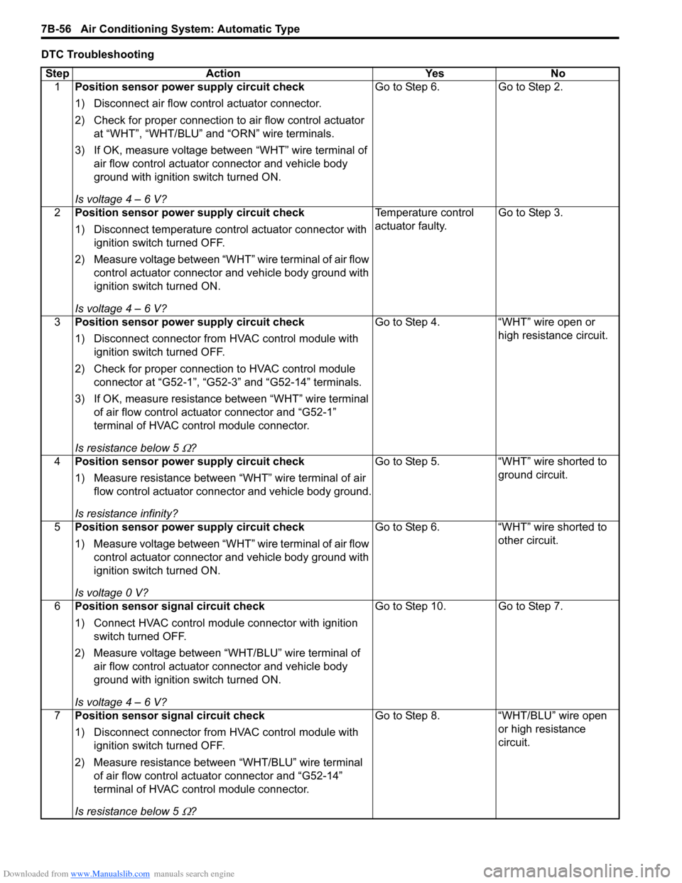
DTC TroubleshootingStep Action YesNo
1 Position sensor power supply circuit check
1) Disconnect air flow control actuator connector.
2) Check for proper connection to air flow control actuator
at “WHT”, “WHT/BLU” and “ORN” wire terminals.
3) If OK, measure voltage between “WHT” wire terminal of air flow control actuator connector and vehicle body
ground with ignition switch turned ON.
Is voltage 4 – 6 V? Go to Step 6.
Go to Step 2.
2 Position sensor power supply circuit check
1) Disconnect temperature control actuator connector with
ignition switch turned OFF.
2) Measure voltage between “WHT” wire terminal of air flow control actuator connector and vehicle body ground with
ignition switch turned ON.
Is voltage 4 – 6 V? Temperature control
actuator faulty.
Go to Step 3.
3 Position sensor power supply circuit check
1) Disconnect connector from HVAC control module with
ignition switch turned OFF.
2) Check for proper connection to HVAC control module connector at “G52-1”, “G52-3” and “G52-14” terminals.
3) If OK, measure resistance between “WHT” wire terminal of air flow control actuator connector and “G52-1”
terminal of HVAC control module connector.
Is resistance below 5
Ω? Go to Step 4. “WHT” wire open or
high resistance circuit.
4 Position sensor power supply circuit check
1) Measure resistance between “WHT” wire terminal of air
flow control actuator connector and vehicle body ground.
Is resistance infinity? Go to Step 5. “WHT” wire shorted to
ground circuit.
5 Position sensor power supply circuit check
1) Measure voltage between “WHT” wire terminal of air flow
control actuator connector and vehicle body ground with
ignition switch turned ON.
Is voltage 0 V? Go to Step 6. “WHT” wire shorted to
other circuit.
6 Position sensor signal circuit check
1) Connect HVAC control module connector with ignition
switch turned OFF.
2) Measure voltage between “WHT/BLU” wire terminal of air flow control actuator connector and vehicle body
ground with ignition switch turned ON.
Is voltage 4 – 6 V? Go to Step 10. Go to Step 7.
7 Position sensor signal circuit check
1) Disconnect connector from HVAC control module with
ignition switch turned OFF.
2) Measure resistance between “WHT/BLU” wire terminal of air flow control actuator connector and “G52-14”
terminal of HVAC control module connector.
Is resistance below 5
Ω? Go to Step 8. “WHT/BLU” wire open
or high resistance
circuit.