9F-15 SUZUKI SWIFT 2005 2.G Service Workshop Manual
[x] Cancel search | Manufacturer: SUZUKI, Model Year: 2005, Model line: SWIFT, Model: SUZUKI SWIFT 2005 2.GPages: 1496, PDF Size: 34.44 MB
Page 1170 of 1496

Downloaded from www.Manualslib.com manuals search engine 9-iv Table of Contents
Rear End Door Opener System Symptom Diagnosis .......................................................... 9F-5
Rear End Door Opener System Operation Inspection .......................................................... 9F-5
Repair Instructions ........... ................................... 9F-6
Front Door Lock Assembly Components ............ 9F-6
Front Door Lock Assembly Removal and Installation ......................................................... 9F-6
Front Door Lock Assembly Inspection ................ 9F-8
Power Door Lock Switch In spection.................... 9F-8
Door Key Cylinder Switch Inspection .................. 9F-8
Power Door Lock Actuator Inspection ................. 9F-9
Rear Door Lock Assembly Components ........... 9F-10
Rear Door Lock Assembly Removal and Installation ....................................................... 9F-10
Rear Door Lock Assembly Inspection ............... 9F-10
Rear End Door Lock Assembly Components.... 9F-11
Rear End Door Lock Assembly Removal and Installation ....................................................... 9F-11
Rear End Door Lock Assembly Inspection........ 9F-12
Rear End Door Opener Switch Inspection ........ 9F-12
Replacement of Transmitte r Battery ................. 9F-13
Programming Transmitter Code for Keyless Entry System (Vehicle without Keyless Start
System) ........................................................... 9F-13
Keyless Entry Answer Back Function
Change-over Procedure (If Equipped) ............ 9F-14
Keyless Entry Receiver Removal and
Installation ....................................................... 9F-14
Keyless Entry Receiver and Its Circuit Inspection ........................................................ 9F-15
Specifications .... ................................................. 9F-16
Tightening Torque Specifications ...................... 9F-16
Special Tools and Equipmen t ........................... 9F-16
Recommended Service Material ....................... 9F-16
Seats ............. ............................................ 9G-1
Repair Instructions ............................................. 9G-1
Front Seat Components ..................................... 9G-1
Front Seat Removal and In stallation .................. 9G-2
Rear Seat Components...................................... 9G-3
Rear Seat Removal and Installation................... 9G-4
Specifications .... .................................................. 9G-4
Tightening Torque Specifications ....................... 9G-4
Special Tools and Equipmen t ............................ 9G-4
Recommended Service Material ........................ 9G-4
Interior Trim ................. ............................ 9H-1
Repair Instructions ............ ..................................9H-1
Floor Carpet Removal and Installation ................9H-1
Head Lining Removal and Installation.................9H-1
Console Box Components ..................................9H-2
Specifications ..................... ..................................9H-3
Tightening Torque Specifications ........................9H-3
Hood / Fenders / Doors ...... ...................... 9J-1
Repair Instructions ............ .................................. 9J-1
Hood Removal and Installation ........................... 9J-1
Hood Inspection and Adjustment ........................ 9J-1
Front Fender Components .................................. 9J-2
Front Fender Removal and Installation ............... 9J-2
Front Door Assembly Comp onents ..................... 9J-3
Front Door Assembly Removal and Installation ......................................................... 9J-3
Rear Door Assembly Components...................... 9J-5
Rear Door Assembly Removal and Installation ......................................................... 9J-5
Rear End Door Assembly Components .............. 9J-6
Rear End Door Assembly Removal and Installation ......................................................... 9J-6
Specifications ..................... .................................. 9J-8
Tightening Torque Specifications ........................ 9J-8
Special Tools and Equipmen t ............................. 9J-8
Recommended Service Material ......................... 9J-8
Body Structure............... .......................... 9K-1
Repair Instructions ............ ..................................9K-1
Front Bumper and Rear Bumper Components .... 9K-1
Cowl Top Components........................................ 9K-2
Specifications ..................... ..................................9K-3
Body Dimensions ................................................ 9K-3
Panel Clearance................................................ 9K-10
Paint / Coatings ............. ...........................9L-1
General Description ............................................. 9L-1
Anti-Corrosion Treatment Construction............... 9L-1
Plastic Parts Finishing ......................................... 9L-2
Component Location ............ ............................... 9L-3
Sealant Application Areas ................................... 9L-3
Under Coating Application Areas ........................ 9L-8
Anti-Corrosion Compound Application Area ..... 9L-10
Exterior Trim ...... ...................................... 9M-1
Repair Instructions ......... .................................... 9M-1
Roof Molding Components................................. 9M-1
Splash Guard (If Equipped) Components .......... 9M-2
Page 1361 of 1496

Downloaded from www.Manualslib.com manuals search engine Security and Locks: 9F-15
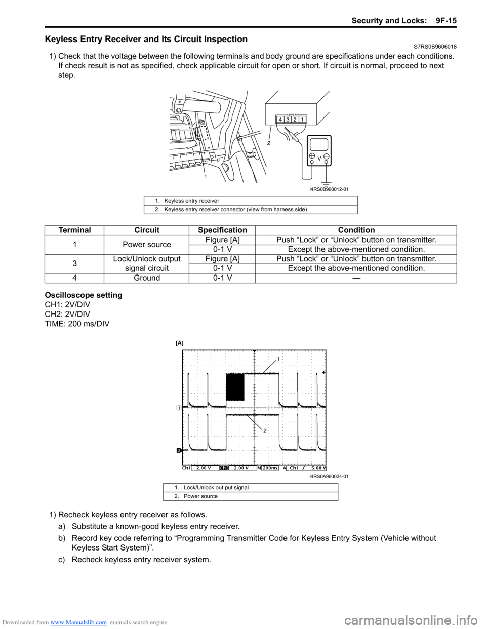
Keyless Entry Receiver and Its Circuit InspectionS7RS0B9606018
1) Check that the voltage between the following terminals and body ground are specifications under each conditions.
If check result is not as specified, ch eck applicable circuit for open or short. If circuit is normal, proceed to next
step.
Oscilloscope setting
CH1: 2V/DIV
CH2: 2V/DIV
TIME: 200 ms/DIV 1) Recheck keyless entry receiver as follows.
a) Substitute a known-good keyless entry receiver.
b) Record key code referring to “Programming Transmit ter Code for Keyless Entry System (Vehicle without
Keyless Start System)”.
c) Recheck keyless entry receiver system.
1. Keyless entry receiver
2. Keyless entry receiver connector (view from harness side)
1234
V
1 2
I4RS0B960012-01
Terminal
Circuit Specification Condition
1 Power source Figure [A] Push “Lock” or “Unlock” button on transmitter.
0-1 V Except the above-mentioned condition.
3 Lock/Unlock output
signal circuit Figure [A] Push “Lock” or “Unlock” button on transmitter.
0-1 V Except the above-mentioned condition.
4G ro un d0 -1 V —
1. Lock/Unlock out put signal
2. Power source
I4RS0A960024-01