Lamp SUZUKI SWIFT 2005 2.G Service Workshop Manual
[x] Cancel search | Manufacturer: SUZUKI, Model Year: 2005, Model line: SWIFT, Model: SUZUKI SWIFT 2005 2.GPages: 1496, PDF Size: 34.44 MB
Page 13 of 1496
Downloaded from www.Manualslib.com manuals search engine Precautions: 00-8
Precautions for Electrical Circuit ServiceS7RS0B0000008
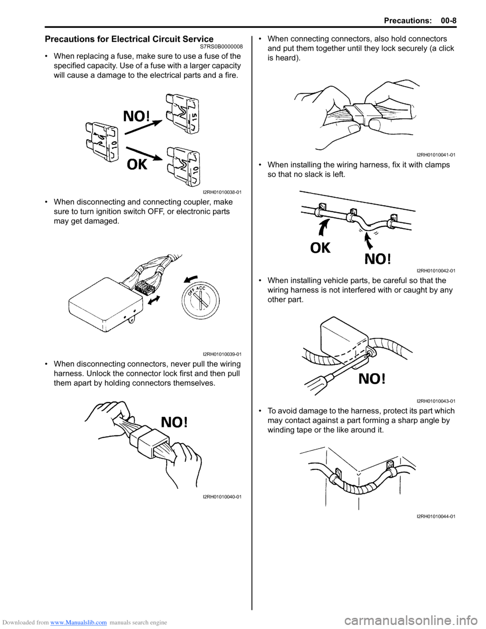
• When replacing a fuse, make sure to use a fuse of the specified capacity. Use of a fuse with a larger capacity
will cause a damage to the electrical parts and a fire.
• When disconnecting and connecting coupler, make sure to turn ignition switch OFF, or electronic parts
may get damaged.
• When disconnecting connectors, never pull the wiring harness. Unlock the connecto r lock first and then pull
them apart by holding connectors themselves. • When connecting connectors, also hold connectors
and put them together until th ey lock securely (a click
is heard).
• When installing the wiring harness, fix it with clamps so that no slack is left.
• When installing vehicle parts, be careful so that the wiring harness is not interfered with or caught by any
other part.
• To avoid damage to the harnes s, protect its part which
may contact against a part forming a sharp angle by
winding tape or the like around it.
I2RH01010038-01
I2RH01010039-01
I2RH01010040-01
I2RH01010041-01
I2RH01010042-01
I2RH01010043-01
I2RH01010044-01
Page 22 of 1496
Downloaded from www.Manualslib.com manuals search engine 0A-1 General Information:
General Information
General Information
General Description
AbbreviationsS7RS0B0101001
A:
ABDC: After Bottom Dead Center
ABS: Anti-lock Brake System
AC: Alternating Current
A/C: Air Conditioning
A-ELR: Automatic-Emergency Locking Retractor
A/F: Air Fuel Mixture Ratio
ALR: Automatic Locking Retractor
API: American Petroleum Institute
APP sensor: Accelerator Pedal Position Sensor
A/T: Automatic Transmission , Automatic Transaxle
AT D C : After Top Dead Center
ATF: Automatic Transmission Fluid, Automatic
Transaxle Fluid
B:
B+: Battery Positive Voltage
BBDC: Before Bottom Dead Center
BCM: Body Electrical Control Module
BDC: Bottom Dead Center
BTDC: Before Top Dead Center
C:
CAN: Controller Area Network
CKT: Circuit
CKP Sensor: Crankshaft Position Sensor
CMP Sensor: Camshaft Position Sensor
CO: Carbon Monoxide
CPP Switch: Clutch Pedal Position Switch (Clutch
Switch, Clutch Start Switch)
CPU: Central Processing Unit
CRS: Child Restraint System
D:
DC: Direct Current
DLC: Data Link Connector (Assembly Line Diag. Link,
ALDL, Serial Data Link, SDL)
DOHC: Double Over Head Camshaft
DOJ: Double Offset Joint
DRL: Daytime Running Light
DTC: Diagnostic Trouble Code (Diagnostic Code)
E:
EBCM: Electronic Brake Cont rol Module, ABS Control
Module
EBD: Electronic Brake Force Distribution
ECM: Engine Control Module
ECT Sensor: Engine Coolant Temperature Sensor (Water Temp. Sensor, WTS)
EFE Heater: Early Fuel Evaporation Heater (Positive
Temperature Coefficient, PTC Heater)
EGR: Exhaust Gas Recirculation
EGRT Sensor: EGR Temperature Sensor (Recirculated
Exhaust Gas Temp. Sensor, REGTS)
ELR: Emergency Locking Retractor
ESP ®: Electronic Stability Program
EPS: Electronic Power Steering
EVAP: Evaporative Emission EVAP Canister:
Evaporative Emission Canister
(Charcoal Canister)
F:
4WD: 4 Wheel
Drive
G:
GEN: Generator
GND: Ground
GPS: Global Positioning System
H:
HVAC: Heating, Ventilating and Air Conditioning
HC: Hydrocarbons
HO2S: Heated Oxygen Sensor
I:
IAC Valve: Idle Air Control Valve (Idle Speed Control
Solenoid Valve, ISC Solenoid Valve)
IAT Sensor: Intake Air Temperature Sensor (Air
temperature Sensor, ATS)
ICM: Immobilizer Control Module
IG: Ignition
ISC Actuator: Idle Speed Control Actuator
L:
LH: Left Hand
LHD: Left Hand Drive Vehicle
LSPV: Load Sensing Proportioning Valve
M:
MAF Sensor: Mass Air Flow Sensor (Air Flow Sensor, AFS, Air Flow Meter, AFM)
MAP Sensor: Manifold Absolute Pressure Sensor
(Pressure Sensor, PS)
Max: Maximum
MFI: Multiport Fuel Injection (Mu ltipoint Fuel Injection)
Min: Minimum
MIL: Malfunction Indicator Lamp (“SERVICE ENGINE
SOON” Light)
M/T: Manual Transmission, Manual Transaxle
N:
NOx: Nitrogen Oxides
O:
OBD: On-Board Diagnostic System (Self-Diagnosis
Function)
O/D: Overdrive
OHC: Over Head Camshaft
O2S: Oxygen Sensor
P:
PCM: Powertrain Control Module
PCV: Positive Crankcase Ventilation
PNP: Park / Neutral Position
P/S: Power Steering
PSP Switch: Power Steering Pressure Switch (P/S
Pressure Switch)
R:
RH: Right Hand
RHD: Right Hand Drive Vehicle
S:
SAE: Society of Automotive Engineers
Page 31 of 1496
Downloaded from www.Manualslib.com manuals search engine Maintenance and Lubrication: 0B-1
General Information
Maintenance and Lubrication
Precautions
Precautions for Maintenance and LubricationS7RS0B0200001
Air Bag Warning
Refer to “Air Bag Warning in Section 00”.
Scheduled Maintenance
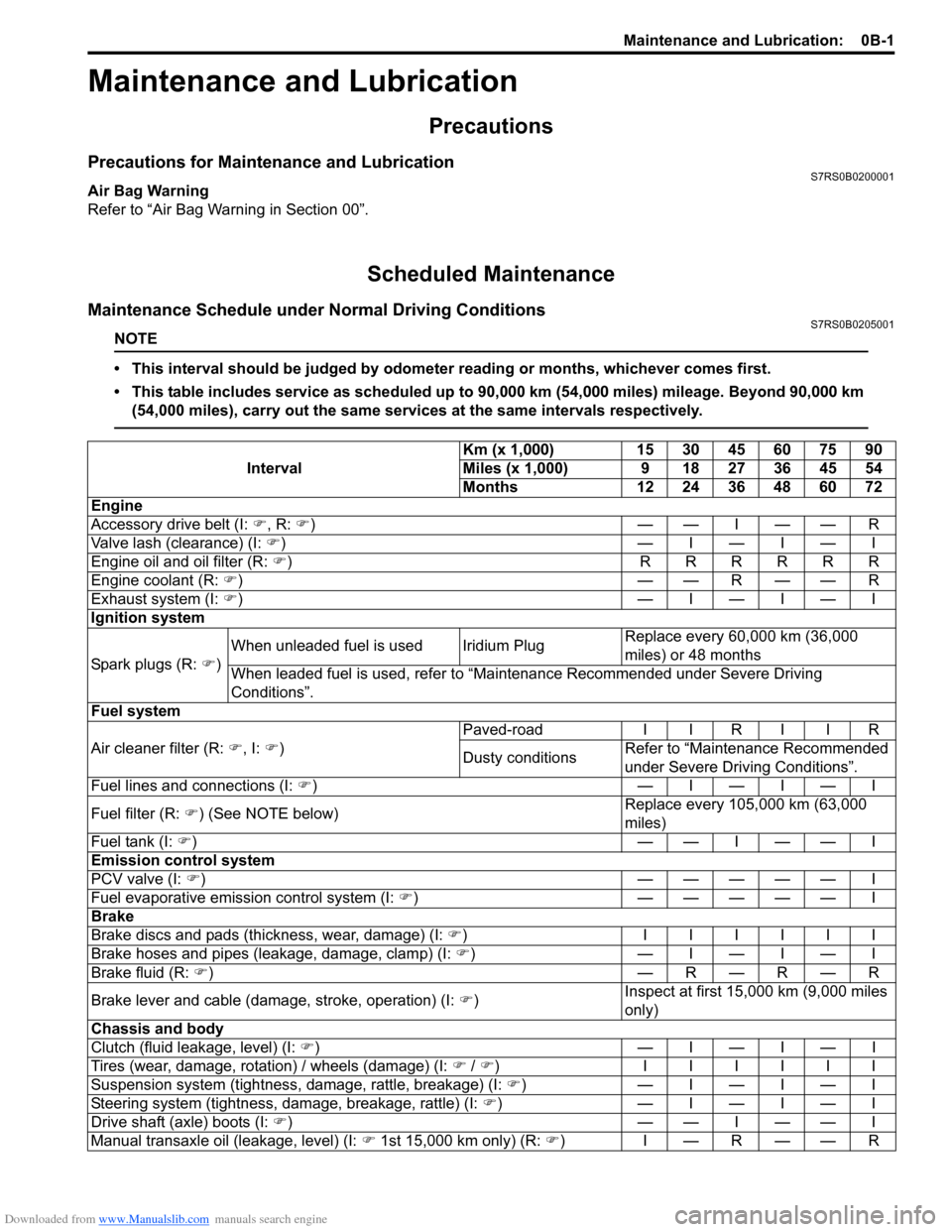
Maintenance Schedule under Normal Driving ConditionsS7RS0B0205001
NOTE
• This interval should be judged by odometer reading or months, whichever comes first.
• This table includes service as scheduled up to 90,000 km (54,000 miles) mileage. Beyond 90,000 km
(54,000 miles), carry out the same services at the same intervals respectively.
Interval Km (x 1,000) 15 30 45 60 75 90
Miles (x 1,000) 9 18 27 36 45 54
Months 12 24 36 48 60 72
Engine
Accessory drive belt (I: �), R: �))——I——R
Valve lash (clearance) (I: �)) —I—I—I
Engine oil and oil filter (R: �)) RRRRRR
Engine coolant (R: �))— —R— — R
Exhaust system (I: �)) —I—I—I
Ignition system
Spark plugs (R: �) )When unleaded fuel is used Iridium Plug
Replace every 60,000 km (36,000
miles) or 48 months
When leaded fuel is used, refer to “Maintenance Recommended under Severe Driving
Conditions”.
Fuel system
Air cleaner filter (R: �), I: �)) Paved-road
I I R I I R
Dusty conditions Refer to “Maintenance Recommended
under Severe Driv
ing Conditions”.
Fuel lines and connections (I: �)) —I—I—I
Fuel filter (R: �)) (See NOTE below) Replace every 105,000 km (63,000
miles)
Fuel tank (I: �))— —I— — I
Emission control system
PCV valve (I: �)) ————— I
Fuel evaporative emission control system (I: �)) ————— I
Brake
Brake discs and pads (thickness, wear, damage) (I: �)) IIIIII
Brake hoses and pipes (leakage, damage, clamp) (I: �)) —I—I—I
Brake fluid (R: �)) —R—R—R
Brake lever and cable (damage, stroke, operation) (I: �)) Inspect at first 15,000 km (9,000 miles
only)
Chassis and body
Clutch (fluid leakage, level) (I: �)) —I—I—I
Tires (wear, damage, rotation) / wheels (damage) (I: �) / �) ) IIIIII
Suspension system (tightness, damage, rattle, breakage) (I: �)) —I—I—I
Steering system (tightness, damage, breakage, rattle) (I: �)) —I—I—I
Drive shaft (axle) boots (I: �))— —I— — I
Manual transaxle oil (leakage, level) (I: �) 1st 15,000 km only) (R: �))I—R——R
Page 36 of 1496
Downloaded from www.Manualslib.com manuals search engine 0B-6 Maintenance and Lubrication:
Exhaust System InspectionS7RS0B0206006
WARNING!
To avoid danger of being burned, do not
touch exhaust system when it is still hot.
Any service on exhaust system should be
performed when it is cool.
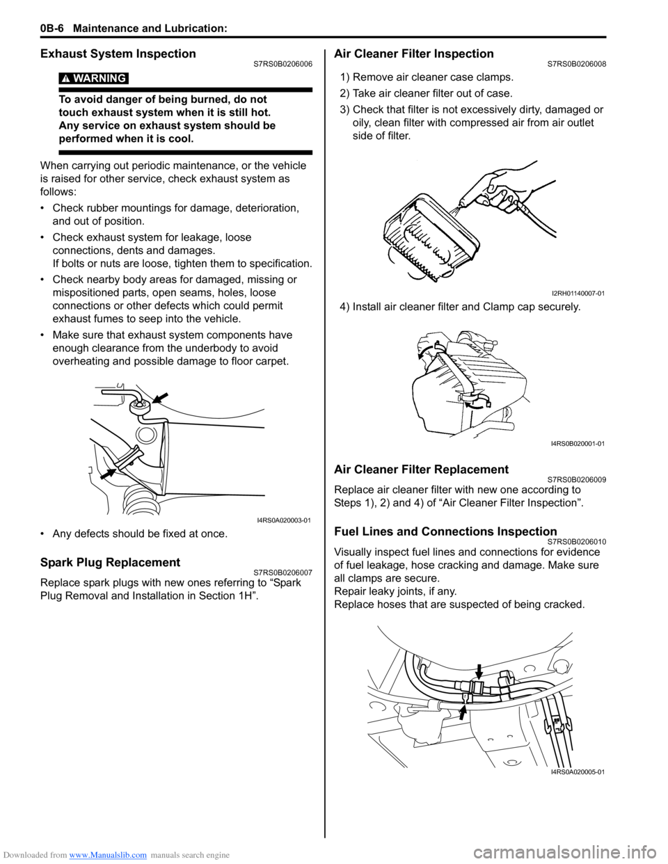
When carrying out periodic maintenance, or the vehicle
is raised for other service, check exhaust system as
follows:
• Check rubber mountings for damage, deterioration, and out of position.
• Check exhaust system for leakage, loose connections, dents and damages.
If bolts or nuts are loose, tighten them to specification.
• Check nearby body areas for damaged, missing or mispositioned parts, ope n seams, holes, loose
connections or other defects which could permit
exhaust fumes to seep into the vehicle.
• Make sure that exhaust system components have enough clearance from the underbody to avoid
overheating and possible damage to floor carpet.
• Any defects should be fixed at once.
Spark Plug ReplacementS7RS0B0206007
Replace spark plugs with new ones referring to “Spark
Plug Removal and Installation in Section 1H”.
Air Cleaner Filter InspectionS7RS0B0206008
1) Remove air cleaner case clamps.
2) Take air cleaner filter out of case.
3) Check that filter is not excessively dirty, damaged or oily, clean filter with compressed air from air outlet
side of filter.
4) Install air cleaner filter and Clamp cap securely.
Air Cleaner Filter ReplacementS7RS0B0206009
Replace air cleaner filter with new one according to
Steps 1), 2) and 4) of “Air Cleaner Filter Inspection”.
Fuel Lines and Connections InspectionS7RS0B0206010
Visually inspect fuel lines and connections for evidence
of fuel leakage, hose cracking and damage. Make sure
all clamps are secure.
Repair leaky joints, if any.
Replace hoses that are suspected of being cracked.
I4RS0A020003-01
I2RH01140007-01
I4RS0B020001-01
I4RS0A020005-01
Page 37 of 1496
Downloaded from www.Manualslib.com manuals search engine Maintenance and Lubrication: 0B-7
Fuel Filter ReplacementS7RS0B0206011
Fuel filter is installed in fuel pump assembly in fuel tank.
Replace fuel filter or fuel pump assembly with new one,
referring to “Fuel Pump Assembly Removal and
Installation in Section 1G” for proper procedure.
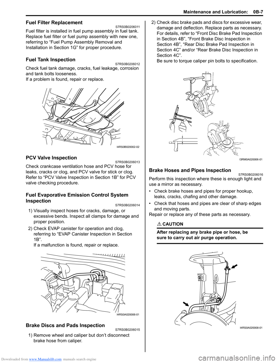
Fuel Tank InspectionS7RS0B0206012
Check fuel tank damage, cracks, fuel leakage, corrosion
and tank bolts looseness.
If a problem is found, repair or replace.
PCV Valve InspectionS7RS0B0206013
Check crankcase ventilation hose and PCV hose for
leaks, cracks or clog, and PCV valve for stick or clog.
Refer to “PCV Valve Inspection in Section 1B” for PCV
valve checking procedure.
Fuel Evaporative Emission Control System
Inspection
S7RS0B0206014
1) Visually inspect hoses for cracks, damage, or excessive bends. Inspect a ll clamps for damage and
proper position.
2) Check EVAP canister for operation and clog, referring to “EVAP Canister Inspection in Section
1B”.
If a malfunction is found, repair or replace.
Brake Discs and Pads InspectionS7RS0B0206015
1) Remove wheel and caliper but don’t disconnect brake hose from caliper. 2) Check disc brake pads and discs for excessive wear,
damage and deflection. Replace parts as necessary.
For details, refer to “Front Disc Brake Pad Inspection
in Section 4B”, “Front Brake Disc Inspection in
Section 4B”, “Rear Disc Brake Pad Inspection in
Section 4C” and/or “Rear Brake Disc Inspection in
Section 4C”.
Be sure to torque caliper pin bolts to specification.
Brake Hoses and Pipes InspectionS7RS0B0206016
Perform this inspection where these is enough light and
use a mirror as necessary.
• Check brake hoses and pipes for proper hookup, leaks, cracks, chafing and other damage.
• Check that hoses and pipes are clear of sharp edges and moving parts.
Repair or replace any of these parts as necessary.
CAUTION!
After replacing any brake pipe or hose, be
sure to carry out air purge operation.
I4RS0B020002-02
I4RS0A020006-01
I3RM0A020006-01
I4RS0A020008-01
Page 41 of 1496
Downloaded from www.Manualslib.com manuals search engine Maintenance and Lubrication: 0B-11
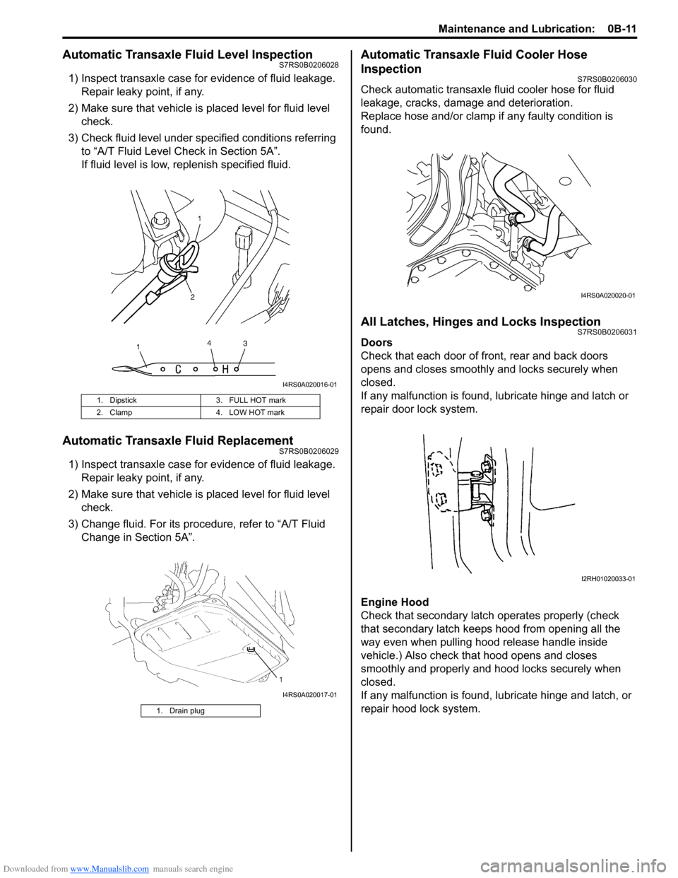
Automatic Transaxle Fluid Level InspectionS7RS0B0206028
1) Inspect transaxle case for evidence of fluid leakage.Repair leaky point, if any.
2) Make sure that vehicle is placed level for fluid level check.
3) Check fluid level under spec ified conditions referring
to “A/T Fluid Level Check in Section 5A”.
If fluid level is low, replenish specified fluid.
Automatic Transaxle Fluid ReplacementS7RS0B0206029
1) Inspect transaxle case for evidence of fluid leakage. Repair leaky point, if any.
2) Make sure that vehicle is placed level for fluid level check.
3) Change fluid. For its procedure, refer to “A/T Fluid Change in Section 5A”.
Automatic Transaxle Fluid Cooler Hose
Inspection
S7RS0B0206030
Check automatic transaxle fluid cooler hose for fluid
leakage, cracks, damage and deterioration.
Replace hose and/or clamp if any faulty condition is
found.
All Latches, Hinges and Locks InspectionS7RS0B0206031
Doors
Check that each door of front, rear and back doors
opens and closes smoothly and locks securely when
closed.
If any malfunction is found, lubricate hinge and latch or
repair door lock system.
Engine Hood
Check that secondary latch operates properly (check
that secondary latch keeps hood from opening all the
way even when pulling hood release handle inside
vehicle.) Also check that hood opens and closes
smoothly and properly and hood locks securely when
closed.
If any malfunction is found, l ubricate hinge and latch, or
repair hood lock system.
1. Dipstick 3. FULL HOT mark
2. Clamp 4. LOW HOT mark
1. Drain plug
I4RS0A020016-01
I4RS0A020017-01
I4RS0A020020-01
I2RH01020033-01
Page 45 of 1496
Downloaded from www.Manualslib.com manuals search engine Table of Contents 1- i
1
Section 1
CONTENTS
Engine
Precautions ................................................. 1-1
Precautions............................................................. 1-1
Precautions for Engine .......................................... 1-1
Engine General Information and
Diagnosis ............. .................................... 1A-1
Precautions........................................................... 1A-1
Precautions on Engine Service ........................... 1A-1
Precaution on On-Board Diagnostic (OBD) System .............................................................. 1A-1
Precautions in Diagnosing Trouble ..................... 1A-1
Precautions of ECM Circuit Inspection................ 1A-2
Precautions of Electric Throttle Body System
Calibration ......................................................... 1A-2
General Description ............................................. 1A-2 Statement on Cleanliness and Care ................... 1A-2
Engine Diagnosis General Description ............... 1A-3
On-Board Diagnostic System Description ........... 1A-3
Data Link Connector (DLC) ................................. 1A-6
Engine and Emission Control System Description ........................................................ 1A-6
CAN Communication System Description........... 1A-7
Air Intake System Description ............................. 1A-9
Description of Electric Throttle Body System ...... 1A-9
Description of Electric Throttle Body System Calibration ....................................................... 1A-10
Fuel Cut Control Description ............................. 1A-10
Generator Control System Description ............. 1A-11
Electronic Control System Description .............. 1A-12
Engine and Emission Control Input / Output Table ............................................................... 1A-18
Schematic and Routing Diagram ...................... 1A-19 Engine and Emission Control System Diagram .......................................................... 1A-19
Component Locatio n ......................................... 1A-21
Electronic Control System Components Location .......................................................... 1A-21
Diagnostic Information and Procedures .......... 1A-22 Engine and Emission Control System Check.... 1A-22
Malfunction Indicator Lamp (MIL) Check .......... 1A-25
DTC Check ....................................................... 1A-26
DTC Clearance ................................................. 1A-27
DTC Table ......................................................... 1A-27
Fail-Safe Table ................ .................................. 1A-31 Scan Tool Data ................................................. 1A-33
Visual Inspection ............................................... 1A-37
Engine Basic Inspection .................................... 1A-38
Engine Symptom Diagnosis .............................. 1A-41
MIL Does Not Come ON with Ignition Switch
ON and Engine Stop (but Engine Can Be
Started) ........................................................... 1A-47
Malfunction Indicator Lamp Remains ON after Engine Starts................................................... 1A-48
DTC P0010: “A” Camshaft Position Actuator Circuit .............................................................. 1A-49
DTC P0011 / P0012: “A” Camshaft Position - Timing Over-Advanced or System
Performance / -Retarded................................. 1A-52
DTC P0031 / P0032: HO2S Heater Control Circuit Low / High (Sensor-1) .......................... 1A-54
DTC P0037 / P0038: HO2S Heater Control Circuit Low / High (Sensor-2) .......................... 1A-56
DTC P0101: Mass or Volume Air Flow Circuit Range / Performance ...................................... 1A-58
DTC P0102: Mass or Volume Air Flow Circuit Low Input......................................................... 1A-61
DTC P0103: Mass or Volume Air Flow Circuit High Input ........................................................ 1A-63
DTC P0106: Manifold Absolute Pressure /
Barometric Pressure Circuit Range /
Performance.................................................... 1A-64
DTC P0107: Manifold Absolute Pressure /
Barometric Pressure Circ uit Low Input............ 1A-66
DTC P0108: Manifold Absolute Pressure /
Barometric Pressure Circ uit High Input ........... 1A-67
DTC P0111: Intake Air Temperature Sensor 1 Circuit Range / Performance ........................... 1A-69
DTC P0112: Intake Air Temperature Sensor 1 Circuit Low ...................................................... 1A-72
DTC P0113: Intake Air Temperature 1 Sensor Circuit High...................................................... 1A-74
DTC P0116: Engine Coolant Temperature Circuit Range / Performance ........................... 1A-76
DTC P0117: Engine Coolant Temperature Circuit Low ...................................................... 1A-79
DTC P0118: Engine Coolant Temperature Circuit High...................................................... 1A-81
DTC P0122: Throttle / Pedal Position Sensor / Switch “A” (Main) Circuit Low ........................ 1A-83
Page 53 of 1496
Downloaded from www.Manualslib.com manuals search engine Engine General Information and Diagnosis: 1A-3
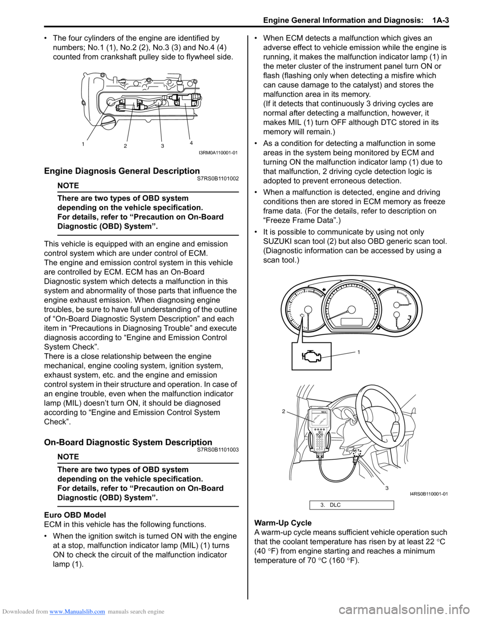
• The four cylinders of the engine are identified by numbers; No.1 (1), No.2 (2 ), No.3 (3) and No.4 (4)
counted from crankshaft pulley side to flywheel side.
Engine Diagnosis General DescriptionS7RS0B1101002
NOTE
There are two types of OBD system
depending on the vehicle specification.
For details, refer to “Precaution on On-Board
Diagnostic (OBD) System”.
This vehicle is equipped with an engine and emission
control system which are under control of ECM.
The engine and emission control system in this vehicle
are controlled by ECM. ECM has an On-Board
Diagnostic system which detects a malfunction in this
system and abnormality of those parts that influence the
engine exhaust emission. When diagnosing engine
troubles, be sure to have full understanding of the outline
of “On-Board Diagnostic System Description” and each
item in “Precautions in Diagnosing Trouble” and execute
diagnosis according to “Engine and Emission Control
System Check”.
There is a close relationship between the engine
mechanical, engine cooling system, ignition system,
exhaust system, etc. and the engine and emission
control system in their structure and operation. In case of
an engine trouble, even when the malfunction indicator
lamp (MIL) doesn’t turn ON, it should be diagnosed
according to “Engine and Emission Control System
Check”.
On-Board Diagnostic System DescriptionS7RS0B1101003
NOTE
There are two types of OBD system
depending on the vehicle specification.
For details, refer to “Precaution on On-Board
Diagnostic (OBD) System”.
Euro OBD Model
ECM in this vehicle has the following functions.
• When the ignition switch is turned ON with the engine at a stop, malfunction indicator lamp (MIL) (1) turns
ON to check the circuit of the malfunction indicator
lamp (1). • When ECM detects a malfunction which gives an
adverse effect to vehicle emission while the engine is
running, it makes the malfunction indicator lamp (1) in
the meter cluster of the inst rument panel turn ON or
flash (flashing only when detecting a misfire which
can cause damage to the catalyst) and stores the
malfunction area in its memory.
(If it detects that contin uously 3 driving cycles are
normal after detecting a malfunction, however, it
makes MIL (1) turn OFF although DTC stored in its
memory will remain.)
• As a condition for detecting a malfunction in some areas in the system being monitored by ECM and
turning ON the malfunction indicator lamp (1) due to
that malfunction, 2 driving cycle detection logic is
adopted to prevent erroneous detection.
• When a malfunction is detected, engine and driving conditions then are stored in ECM memory as freeze
frame data. (For the details, refer to description on
“Freeze Frame Data”.)
• It is possible to communicate by using not only SUZUKI scan tool (2) but also OBD generic scan tool.
(Diagnostic information can be accessed by using a
scan tool.)
Warm-Up Cycle
A warm-up cycle means sufficie nt vehicle operation such
that the coolant temperature has risen by at least 22 °C
(40 °F) from engine starting and reaches a minimum
temperature of 70 °C (160 ° F).
1
23 4
I3RM0A110001-01
3. DLC
2
3
1
I4RS0B110001-01
Page 54 of 1496
Downloaded from www.Manualslib.com manuals search engine 1A-4 Engine General Information and Diagnosis:
Driving Cycle
A “Driving Cycle” consists of engine startup and engine
shutoff.
2 Driving Cycle Detection Logic
The malfunction detected in the first driving cycle is
stored in ECM memory (in t he form of pending DTC) but
the malfunction indicator lamp does not light at this time.
It lights up at the second detection of same malfunction
also in the next driving cycle.
Pending DTC
Pending DTC means a DTC detected and stored
temporarily at 1 driving cycle of the DTC which is
detected in the 2 driving cycle detection logic.
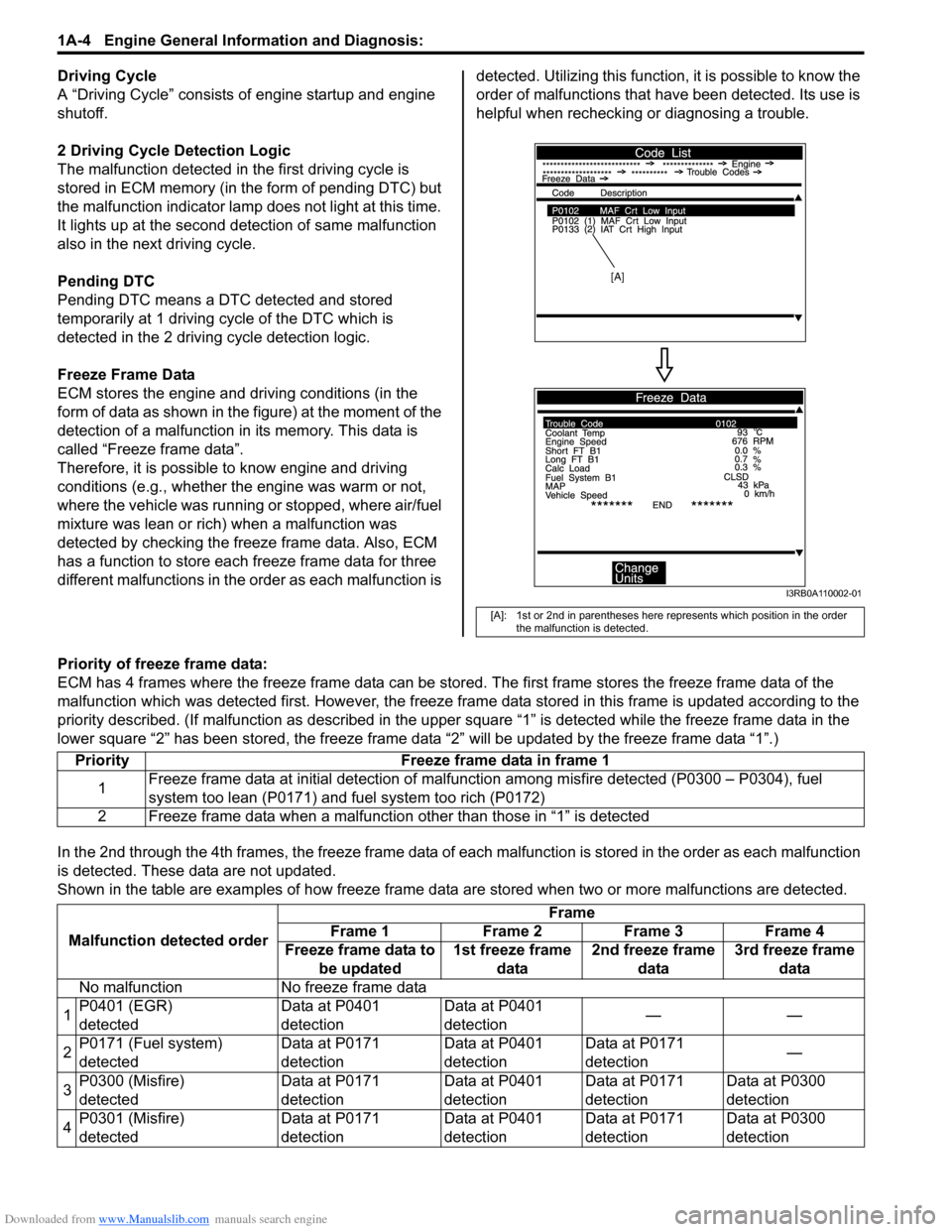
Freeze Frame Data
ECM stores the engine and driving conditions (in the
form of data as shown in the figure) at the moment of the
detection of a malfunction in its memory. This data is
called “Freeze frame data”.
Therefore, it is possible to know engine and driving
conditions (e.g., whether the engine was warm or not,
where the vehicle was running or stopped, where air/fuel
mixture was lean or rich) when a malfunction was
detected by checking the freeze frame data. Also, ECM
has a function to store each freeze frame data for three
different malfunctions in the order as each malfunction is detected. Utilizing this function,
it is possible to know the
order of malfunctions that ha ve been detected. Its use is
helpful when rechecking or diagnosing a trouble.
Priority of freeze frame data:
ECM has 4 frames where the freeze frame data can be stor ed. The first frame stores the freeze frame data of the
malfunction which was detected first. Howe ver, the freeze frame data stored in this frame is updated according to the
priority described. (If malfunction as described in the upper square “1” is detected while the freeze frame data in the
lower square “2” has been stored, the freeze frame data “2” will be updated by the freeze frame data “1”.)
In the 2nd through the 4th frames, the freeze frame data of each malfunction is stored in the order as each malfunction
is detected. These data are not updated.
Shown in the table are examples of how freeze frame data are stored when two or more malfunctions are detected.
[A]: 1st or 2nd in parentheses here represents which position in the order
the malfunction is detected.
[A]
I3RB0A110002-01
Priority Freeze frame data in frame 1
1 Freeze frame data at initial detection of malfuncti
on among misfire detected (P0300 – P0304), fuel
system too lean (P0171) and fuel system too rich (P0172)
2 Freeze frame data when a malfunctio n other than those in “1” is detected
Malfunction detected order Frame
Frame 1 Frame 2 Frame 3 Frame 4
Freeze frame data to be updated 1st freeze frame
data 2nd freeze frame
data 3rd freeze frame
data
No malfunction No freeze frame data
1 P0401 (EGR)
detected Data at P0401
detectionData at P0401
detection
——
2 P0171 (Fuel system)
detected Data at P0171
detectionData at P0401
detectionData at P0171
detection
—
3 P0300 (Misfire)
detected Data at P0171
detectionData at P0401
detectionData at P0171
detectionData at P0300
detection
4 P0301 (Misfire)
detected Data at P0171
detectionData at P0401
detectionData at P0171
detectionData at P0300
detection
Page 55 of 1496
Downloaded from www.Manualslib.com manuals search engine Engine General Information and Diagnosis: 1A-5
Freeze frame data clearance:
The freeze frame data is cleared at the same time as
clearance of DTC.
Non-Euro-OBD
ECM diagnosis troubles which may occur in the area
including the following parts w hen the ignition switch is
ON and the engine is running, and indicates the result by
turning on or flashing malfunction indicator lamp (1).
• Heated oxygen sensor
• ECT sensor
•TP sensor
• APP sensor
• MAF sensor
• IAT sensor
• MAP sensor
• CMP sensor
• CKP sensor
• Knock sensor
• Wheel speed sensor (VSS)
• CPU (Central Processing Unit) of ECM
• Oil control valve
• EGR valve
• EVAP canister purge valve
• Ignition coil
• Starter relay
• Radiator fan relay
• CAN communication
• Barometric pressure sensor
• ECM back up power supply
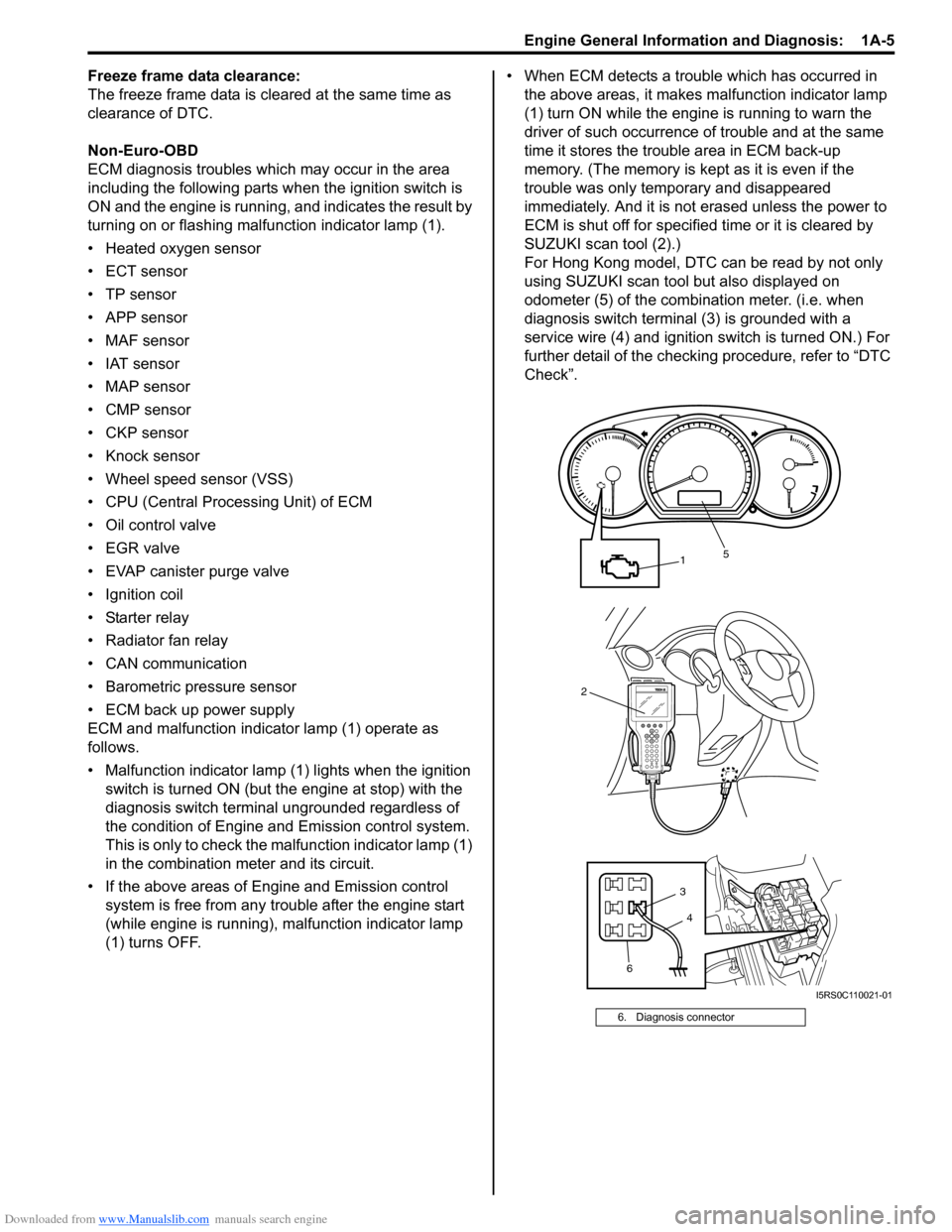
ECM and malfunction indicator lamp (1) operate as
follows.
• Malfunction indicator lamp (1) lights when the ignition switch is turned ON (but t he engine at stop) with the
diagnosis switch terminal ungrounded regardless of
the condition of Engine and Emission control system.
This is only to check the ma lfunction indicator lamp (1)
in the combination meter and its circuit.
• If the above areas of Engine and Emission control system is free from any trouble after the engine start
(while engine is running), malfunction indicator lamp
(1) turns OFF. • When ECM detects a trouble which has occurred in
the above areas, it makes malfunction indicator lamp
(1) turn ON while the engi ne is running to warn the
driver of such occurrence of trouble and at the same
time it stores the trouble area in ECM back-up
memory. (The memory is kept as it is even if the
trouble was only temporary and disappeared
immediately. And it is not erased unless the power to
ECM is shut off for specified time or it is cleared by
SUZUKI scan tool (2).)
For Hong Kong model, DTC can be read by not only
using SUZUKI scan tool but also displayed on
odometer (5) of the combination meter. (i.e. when
diagnosis switch terminal (3) is grounded with a
service wire (4) and ignition switch is turned ON.) For
further detail of the checking procedure, refer to “DTC
Check”.
6. Diagnosis connector
2
1
6 3
5
4
I5RS0C110021-01