Wheel torque specification SUZUKI SWIFT 2005 2.G Service Workshop Manual
[x] Cancel search | Manufacturer: SUZUKI, Model Year: 2005, Model line: SWIFT, Model: SUZUKI SWIFT 2005 2.GPages: 1496, PDF Size: 34.44 MB
Page 21 of 1496
Downloaded from www.Manualslib.com manuals search engine Table of Contents 0- i
0
Section 0
CONTENTS
General Information
General Information ................................ 0A-1
General Description ............................................. 0A-1
Abbreviations ...................................................... 0A-1
Symbols .............................................................. 0A-2
Wire Color Symbols ............................................ 0A-2
Fasteners Information ......................................... 0A-3
Vehicle Lifting Points ........................................... 0A-5
Engine Supporting Points ................................... 0A-7
Vehicle Identification Number ............................. 0A-7
Engine Identification Number .............................. 0A-7
Transmission Identification Number .................... 0A-7
Component Locatio n ........................................... 0A-8
Warning, Caution and Information Labels Location ............................................................ 0A-8
Maintenance and Lubricat ion ................. 0B-1
Precautions........................................................... 0B-1
Precautions for Maintenance and Lubrication ..... 0B-1
Scheduled Maintenance ...................................... 0B-1 Maintenance Schedule under Normal Driving Conditions ......................................................... 0B-1
Maintenance Recommended under Severe Driving Conditions ............................................. 0B-2
Repair Instructions .............................................. 0B-3 Accessory Drive Belt Inspection.......................... 0B-3
Accessory Drive Belt Repl acement ..................... 0B-4
Valve Lash (Clearance) Inspection ..................... 0B-4
Engine Oil and Filter Change .............................. 0B-4
Engine Coolant Change ...... ................................ 0B-5
Exhaust System Inspection ................................. 0B-6
Spark Plug Replacement .................................... 0B-6
Air Cleaner Filter Inspection ................................ 0B-6
Air Cleaner Filter Replac ement ........................... 0B-6 Fuel Lines and Connections Inspection .............. 0B-6
Fuel Filter Replacement ...................................... 0B-7
Fuel Tank Inspection ........................................... 0B-7
PCV Valve Inspection ......................................... 0B-7
Fuel Evaporative Emission Control System
Inspection .......................................................... 0B-7
Brake Discs and Pads Inspection ....................... 0B-7
Brake Hoses and Pipes Inspection ..................... 0B-7
Brake Fluid Inspection......................................... 0B-8
Brake Fluid Replacement .................................... 0B-8
Brake Lever and Cable Inspection ...................... 0B-8
Clutch Fluid Inspection ........................................ 0B-8
Tires Inspection ................................................... 0B-9
Wheel Discs Inspection ....................................... 0B-9
Wheel Bearing Inspection ................................... 0B-9
Suspension System Inspection ........................... 0B-9
Steering System Inspection .............................. 0B-10
Drive Shaft (Axle) Boots Inspection .................. 0B-10
Manual Transaxle Oil Inspection ....................... 0B-10
Manual Transaxle Oil Replacement .................. 0B-10
Automatic Transaxle Fluid Level Inspection...... 0B-11
Automatic Transaxle Fluid Replacement .......... 0B-11
Automatic Transaxle Fluid Cooler Hose Inspection ........................................................ 0B-11
All Latches, Hinges and Locks Inspection......... 0B-11
HVAC Air Filter (If Equipped) Inspection ........... 0B-12
HVAC Air Filter (If Equipped) Replacement ...... 0B-12
Final Inspection for Maint enance Service ......... 0B-12
Specifications .................... .................................0B-13
Tightening Torque Specifications ...................... 0B-13
Special Tools and Equipmen t ...........................0B-13
Recommended Fluids and Lubricants............... 0B-13
Special Tool ...................................................... 0B-14
Page 37 of 1496
Downloaded from www.Manualslib.com manuals search engine Maintenance and Lubrication: 0B-7
Fuel Filter ReplacementS7RS0B0206011
Fuel filter is installed in fuel pump assembly in fuel tank.
Replace fuel filter or fuel pump assembly with new one,
referring to “Fuel Pump Assembly Removal and
Installation in Section 1G” for proper procedure.
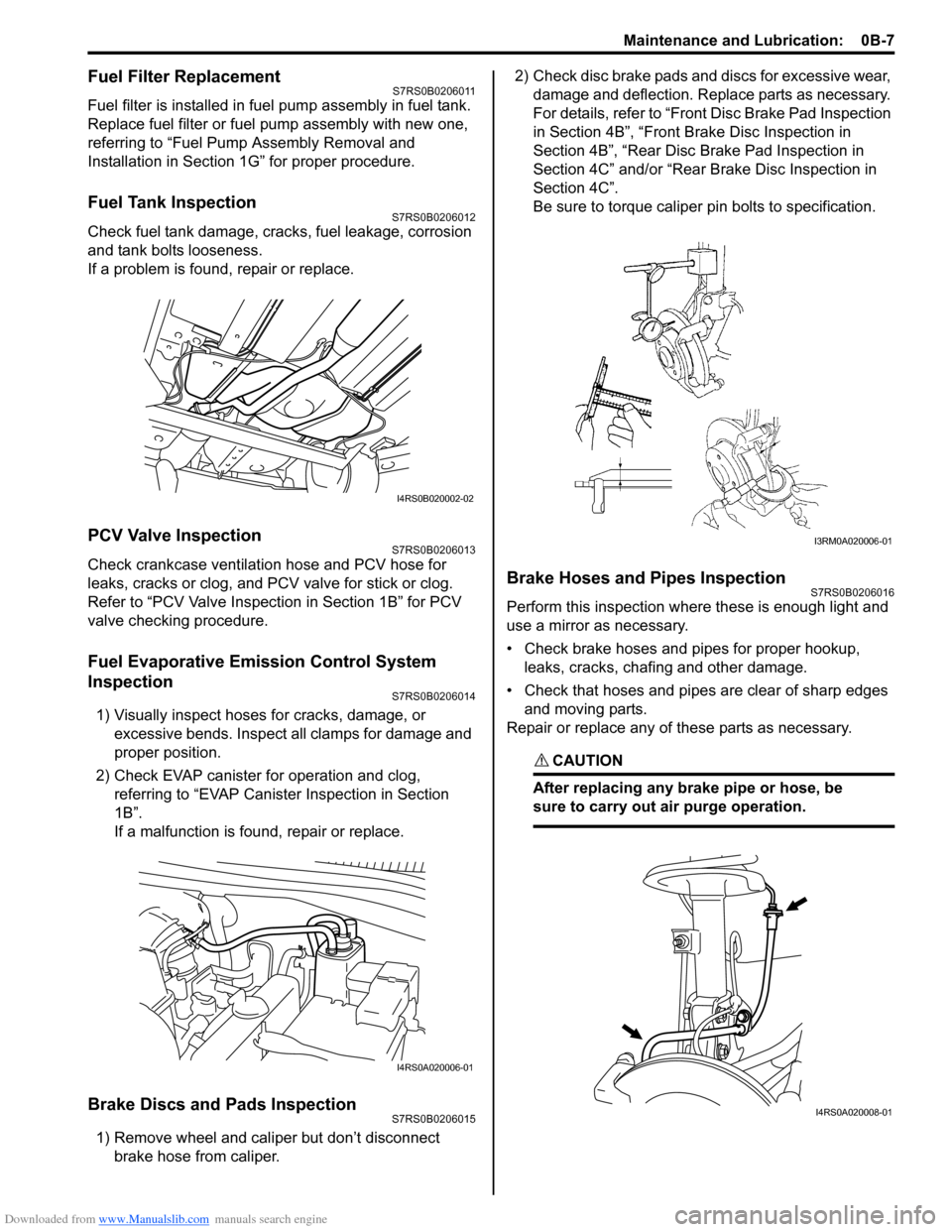
Fuel Tank InspectionS7RS0B0206012
Check fuel tank damage, cracks, fuel leakage, corrosion
and tank bolts looseness.
If a problem is found, repair or replace.
PCV Valve InspectionS7RS0B0206013
Check crankcase ventilation hose and PCV hose for
leaks, cracks or clog, and PCV valve for stick or clog.
Refer to “PCV Valve Inspection in Section 1B” for PCV
valve checking procedure.
Fuel Evaporative Emission Control System
Inspection
S7RS0B0206014
1) Visually inspect hoses for cracks, damage, or excessive bends. Inspect a ll clamps for damage and
proper position.
2) Check EVAP canister for operation and clog, referring to “EVAP Canister Inspection in Section
1B”.
If a malfunction is found, repair or replace.
Brake Discs and Pads InspectionS7RS0B0206015
1) Remove wheel and caliper but don’t disconnect brake hose from caliper. 2) Check disc brake pads and discs for excessive wear,
damage and deflection. Replace parts as necessary.
For details, refer to “Front Disc Brake Pad Inspection
in Section 4B”, “Front Brake Disc Inspection in
Section 4B”, “Rear Disc Brake Pad Inspection in
Section 4C” and/or “Rear Brake Disc Inspection in
Section 4C”.
Be sure to torque caliper pin bolts to specification.
Brake Hoses and Pipes InspectionS7RS0B0206016
Perform this inspection where these is enough light and
use a mirror as necessary.
• Check brake hoses and pipes for proper hookup, leaks, cracks, chafing and other damage.
• Check that hoses and pipes are clear of sharp edges and moving parts.
Repair or replace any of these parts as necessary.
CAUTION!
After replacing any brake pipe or hose, be
sure to carry out air purge operation.
I4RS0B020002-02
I4RS0A020006-01
I3RM0A020006-01
I4RS0A020008-01
Page 43 of 1496
Downloaded from www.Manualslib.com manuals search engine Maintenance and Lubrication: 0B-13
Brake
Foot brake
Check the following:
• that brake pedal has proper travel,
• that brake works properly,
• that it is free from noise,
• that vehicle does not pull to one side when brake is applied.
• and that brake do not drag.
Parking brake
Check that lever has proper travel.
WARNING!
With vehicle parked on a fairly steep slope,
make sure nothing is in the way downhill to
avoid any personal injury or property
damage. Be prepared to apply regular brake
quickly even if vehicle should start to move.
Check to ensure that parking brake is fully effective
when the vehicle is stopped on the safe slope and brake
lever is pulled all the way.
Steering
• Check to ensure that steering wheel is free from instability, or abnormally heavy feeling. • Check that the vehicle does not wander or pull to one
side.
Engine
• Check that engine responds readily at all speeds.
• Check that engine is free from abnormal noise and abnormal vibration.
Body, Wheels and Power Transmitting System
Check that body, wheels and power transmitting system
are free from abnormal noise and abnormal vibration or
any other abnormal condition.
Meters and Gauge
Check that speedometer, odometer, fuel meter,
temperature gauge, etc. are operating accurately.
Lights
Check that all lights operate properly.
Windshield Defroster
Periodically check that ai r comes out from defroster
outlet when operating heater or air conditioning.
Set mode control lever to defroster position and fan
switch lever to “HI” position for this check.
Specifications
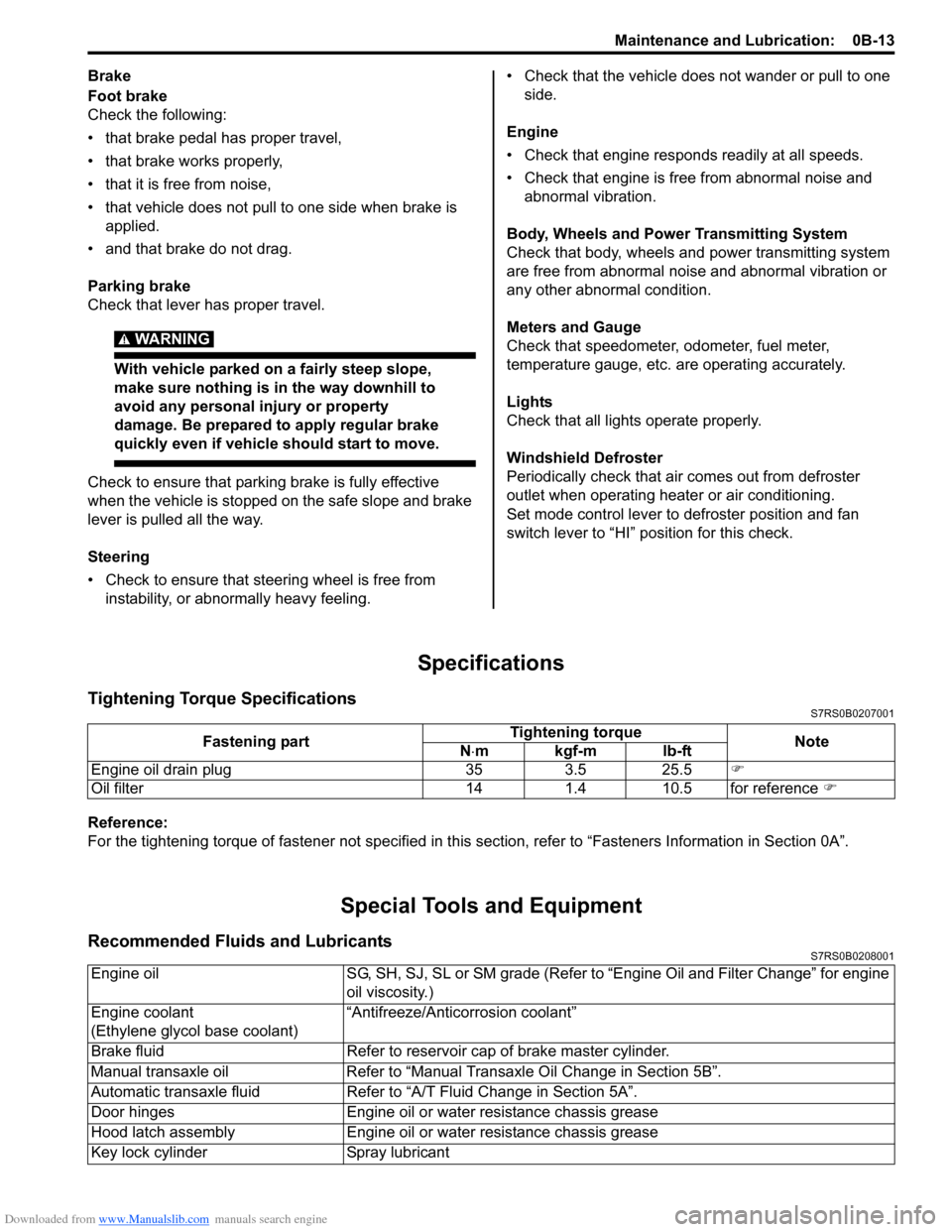
Tightening Torque SpecificationsS7RS0B0207001
Reference:
For the tightening torque of fastener not specified in this section, refer to “Fasteners Information in Section 0A”.
Special Tools and Equipment
Recommended Fluids and LubricantsS7RS0B0208001
Fastening part Tightening torque
Note
N ⋅mkgf-mlb-ft
Engine oil drain plug 35 3.5 25.5 �)
Oil filter 14 1.4 10.5 for reference �)
Engine oilSG, SH, SJ, SL or SM grade (Refer to “Engine Oil and Filter Change” for engine
oil viscosity.)
Engine coolant
(Ethylene glycol base coolant) “Antifreeze/Antico
rrosion coolant”
Brake fluid Refer to reservoir cap of brake master cylinder.
Manual transaxle oil Refer to “Manual Transaxle Oil Change in Section 5B”.
Automatic transaxle fluid Refer to “A/T Fluid Change in Section 5A”.
Door hinges Engine oil or water resistance chassis grease
Hood latch assembly Engine oil or water resistance chassis grease
Key lock cylinder Spray lubricant
Page 47 of 1496

Downloaded from www.Manualslib.com manuals search engine Table of Contents 1-iii
EVAP Canister Purge Valve and Its Circuit
Inspection.......................................................... 1B-2
Vacuum Passage Inspection .............................. 1B-3
Vacuum Hose and Purge Valve Chamber Inspection.......................................................... 1B-3
EVAP Canister Purge Valve Inspection .............. 1B-3
EVAP Canister Inspection ... ................................ 1B-4
EGR Valve Removal and Installation .................. 1B-4
EGR Valve Inspection ......................................... 1B-4
PCV Hose Inspection .......................................... 1B-4
PCV Valve Inspection ......................................... 1B-5
Special Tools and Equipmen t ............................. 1B-5
Special Tool ........................................................ 1B-5
Engine Electrical Devices .. ..................... 1C-1
Repair Instructions .............................................. 1C-1
ECM Removal and Installation ............................ 1C-1
MAP Sensor Inspection ...................................... 1C-2
Electric Throttle Body Assembly On-Vehicle
Inspection.......................................................... 1C-2
Electric Throttle Body System Calibration ........... 1C-5
APP Sensor Assembly On-V ehicle Inspection .... 1C-5
APP Sensor Assembly Removal and Installation ......................................................... 1C-5
APP Sensor Assembly Inspection ...................... 1C-6
ECT Sensor Removal and In stallation ................ 1C-6
ECT Sensor Inspection ....................................... 1C-7
HO2S-1 and HO2S-2 Heater On-Vehicle Inspection.......................................................... 1C-7
HO2S-1 and HO2S-2 Removal and Installation ......................................................... 1C-7
CMP Sensor Removal and In stallation ............... 1C-8
Camshaft Position (CMP) Se nsor Inspection ...... 1C-8
CKP Sensor Removal and Installation ................ 1C-9
CKP Sensor Inspection ....................................... 1C-9
Knock Sensor Removal and Installation ........... 1C-10
Main Relay, Fuel Pump Relay and Starting
Motor Control Relay Inspection....................... 1C-10
MAF and IAT Sensor On-Vehicle Inspection .... 1C-11
MAF and IAT Sensor Removal and Installation ....................................................... 1C-11
MAF and IAT Sensor Inspection ....................... 1C-12
Electric Load Current Sensor On-Vehicle Inspection........................................................ 1C-12
Specifications ..................................................... 1C-13
Tightening Torque Specifications ...................... 1C-13
Engine Mechanical ......... ......................... 1D-1
General Description ............................................. 1D-1
Engine Construction Description ......................... 1D-1
Camshaft Position Control (VVT Variable Valve Timing) System Description .................... 1D-2
Diagnostic Information and Procedures ............ 1D-4 Compression Check ............................................ 1D-4
Engine Vacuum Check ....................................... 1D-5
Valve Lash (Clearance) Inspection ..................... 1D-6
Repair Instructions .............................................. 1D-9 Air Cleaner Components ..................................... 1D-9
Air Cleaner Element Removal and Installation .... 1D-9 Air Cleaner Element Ins
pection and Cleaning ..1D-10
Cylinder Head Co ver Removal and
Installation .......................................................1D-10
Throttle Body and Intake Manifold
Components ....................................................1D-12
Throttle Body On-Vehicle Inspection.................1D-13
Electric Throttle Body Assembly Removal and Installation .......................................................1D-13
Throttle Body Cleaning......................................1D-14
Intake Manifold Removal and Installation .........1D-14
Engine Mountings Components ........................1D-16
Engine Assembly Removal and Installation ......1D-17
Timing Chain Cover Components .....................1D-20
Timing Chain Cover Removal and Installation ..1D-21
Timing Chain Cover Inspection .........................1D-23
Oil Control Valve Removal and Installation .......1D-23
Oil Control Valve Inspection ..............................1D-24
Timing Chain and Chain Tensioner Components ....................................................1D-24
Timing Chain and Chain Tensioner Removal and Installation ................................................1D-25
Timing Chain and Chain Tensioner Inspection ..1D-27
Camshaft, Tappet and Shim Components ........1D-28
Camshaft, Tappet and Shim Removal and Installation .......................................................1D-29
Camshaft, Tappet and Shim Inspection ............1D-31
Valves and Cylinder Head Components ...........1D-34
Valves and Cylinder Head Removal and
Installation .......................................................1D-35
Valves and Cylinder Head Disassembly and Assembly.........................................................1D-37
Valves and Valve Guides Inspection.................1D-40
Cylinder Head Inspection . .................................1D-42
Valve Spring Inspection ....................................1D-43
Pistons, Piston Rings , Connecting Rods and
Cylinders Components ....................................1D-44
Pistons, Piston Rings , Connecting Rods and
Cylinders Removal and Installation .................1D-45
Pistons, Piston Rings , Connecting Rods and
Cylinders Disassembly and Assembly ............1D-46
Cylinders, Pistons and Piston Rings Inspection ........................................................1D-47
Piston Pins and Connecting Rods Inspection ...1D-49
Crank Pin and Connecting Rod Bearings Inspection ........................................................1D-50
Main Bearings, Cran kshaft and Cylinder
Block Components ..........................................1D-53
Main Bearings, Cran kshaft and Cylinder
Block Removal and Installa tion .......................1D-54
Crankshaft Inspection .......................................1D-57
Main Bearings Inspection . .................................1D-59
Sensor Plate Inspection ....................................1D-63
Rear Oil Seal Inspection ...................................1D-63
Flywheel Inspection...........................................1D-63
Cylinder Block Inspection ..................................1D-63
Specifications .................... .................................1D-64
Tightening Torque Specifications ......................1D-64
Special Tools and Equipmen t ...........................1D-66
Recommended Service Material .......................1D-66
Special Tool ......................................................1D-66
Page 355 of 1496
Downloaded from www.Manualslib.com manuals search engine Engine Lubrication System: 1E-3
6) Start engine and warm engine up to normal operating temperature.
NOTE
Be sure to shift transaxle gear shift lever in
“Neutral” (shift select lever in “P” range for
A/T vehicle), set parking brake and block
drive wheels.
7) After warming up, raise engine speed to 4,000 r/min. and measure oil pressure.
Oil pressure specification
More than 270 kPa (2.7 kg/cm2, 39.8 psi) at 4,000
r/min. (rpm)
8) After checking oil pressure, stop engine and remove oil pressure gauge and attachment.
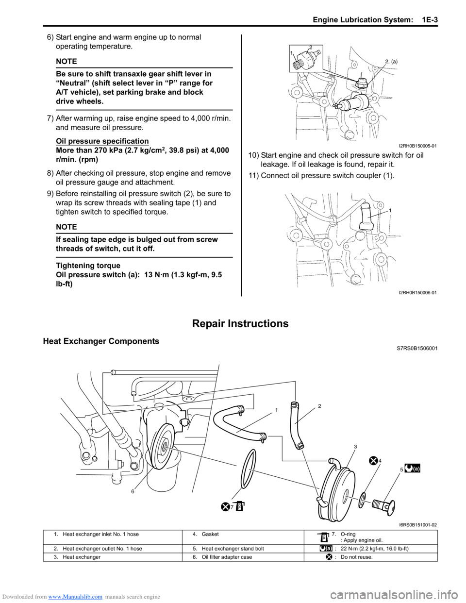
9) Before reinstalling oil pressure switch (2), be sure to
wrap its screw threads with sealing tape (1) and
tighten switch to specified torque.
NOTE
If sealing tape edge is bulged out from screw
threads of switch, cut it off.
Tightening torque
Oil pressure switch (a): 13 N·m (1.3 kgf-m, 9.5
lb-ft) 10) Start engine and check oil pressure switch for oil
leakage. If oil leakage is found, repair it.
11) Connect oil pressure switch coupler (1).
Repair Instructions
Heat Exchanger ComponentsS7RS0B1506001
I2RH0B150005-01
I2RH0B150006-01
3
4
5
7
6
(a)
2
1
I6RS0B151001-02
1. Heat exchanger inlet No. 1 hose 4. Gasket7. O-ring
: Apply engine oil.
2. Heat exchanger outlet No. 1 hose 5. Heat exchanger stand bolt : 22 N⋅m (2.2 kgf-m, 16.0 lb-ft)
3. Heat exchanger 6. Oil filter adapter case : Do not reuse.
Page 429 of 1496
Downloaded from www.Manualslib.com manuals search engine Table of Contents 2- i
2
Section 2
CONTENTS
Suspension
Precautions ................................................. 2-1
Precautions............................................................. 2-1
Precautions on Suspension .................................. 2-1
Suspension General Dia gnosis.............. 2A-1
Diagnostic Information and Procedures ............ 2A-1
Suspension, Wheels and Tires Symptom Diagnosis .......................................................... 2A-1
Front Suspension ........... ......................... 2B-1
General Description ............................................. 2B-1
Front Suspension Construction ........................... 2B-1
Front Wheel Alignment Cons truction .................. 2B-2
Repair Instructions .............................................. 2B-2 Front Wheel Alignment Inspection and Adjustment ........................................................ 2B-2
Front Strut Assembly Comp onents ..................... 2B-4
Front Strut Assembly Removal and Installation ......................................................... 2B-4
Front Strut Assembly Disassembly and Assembly .......................................................... 2B-6
Front Strut Assembly Chec k ............................... 2B-7
Front Wheel Hub and Steering Knuckle Components...................................................... 2B-8
Front Wheel Hub, Steering Knuckle and Wheel Bearing Removal and Installation .......... 2B-8
Front Wheel Hub, Disc, Nut and Bearing Check .............................................................. 2B-12
Suspension Control Arm / Bushing Removal and Installation ................................................ 2B-12
Suspension Control Arm / Bushing Disassembly and Assembly ............................ 2B-13
Suspension Control Arm / Steering Knuckle Check .............................................................. 2B-14
Suspension Control Arm Bushing Check .......... 2B-14
Suspension Control Arm Joint Check ............... 2B-14
Front Suspension Fram e, Stabilizer Bar and/
or Bushings Components................................ 2B-15
Front Suspension Fram e, Stabilizer Bar and/
or Bushings Removal and Installation ............. 2B-15
Front Suspension Frame Ch eck ....................... 2B-19
Front Stabilizer Bar, Bushing and/or Joint Check .............................................................. 2B-19
Front Suspension Fastener s Check .................. 2B-19
Specifications ..................................................... 2B-20 Tightening Torque Specifications ...................... 2B-20
Special Tools and Equipmen t ...........................2B-21
Special Tool ...................................................... 2B-21
Rear Suspension ............ ......................... 2C-1
General Description .............................................2C-1
Rear Suspension Construction ...........................2C-1
Repair Instructions ........... ...................................2C-2
Rear Wheel Alignment Inspection .......................2C-2
Rear Shock Absorber Removal and Installation .........................................................2C-2
Rear Shock Absorber Ins pection ........................2C-3
Rear Shock Absorber Bush Removal and Installation .........................................................2C-4
Rear Shock Absorber Bush Inspection ...............2C-4
Rear Coil Spring Removal and Installation .........2C-4
Spring Upper Seat / Spring Lower Seat Inspection ..........................................................2C-5
Spring Upper Seat and Lower Seat Removal and Installation ..................................................2C-6
Rear Axle Removal and Inst allation ....................2C-6
Trailing Arm, Rear Axle and Coil Spring Inspection ..........................................................2C-9
Rear Axle Bush Inspection ..................................2C-9
Rear Wheel Hub Components ..........................2C-10
Rear Wheel Hub Removal an d Installation .......2C-10
Rear Wheel Disc, bolt and Bearing Inspection ..2C-11
Spindle Removal and Installation ......................2C-12
Spindle Inspection .............................................2C-13
Rear Suspension Fasteners Inspection ............2C-13
Specifications .................... .................................2C-13
Tightening Torque Specifications ......................2C-13
Special Tools and Equipmen t ...........................2C-13
Special Tool ......................................................2C-13
Wheels and Tires ............ ......................... 2D-1
Precautions...........................................................2D-1
Precaution for Emergency Flat Tire Repair Kit ....2D-1
General Description .............................................2D-1 Tires Description .................................................2D-1
Wheels Description .............................................2D-2
Irregular and/or Premature Wear Description .....2D-3
Wear Indicators Description ................................2D-3
Radial Tire Waddle Description...........................2D-4
Radial Tire Lead / Pull Description ......................2D-5
Page 430 of 1496
Downloaded from www.Manualslib.com manuals search engine 2-ii Table of Contents
Balancing Wheels Description ............................ 2D-5
Repair Instructions ..............................................2D-6 General Balance Procedures ..............................2D-6
Tire Rotation........................................................2D-6
Wheel Removal and Installation..........................2D-7
Tire Mounting and Dismounting ..........................2D-8 Tire Repair ..........................................................2D-8
Tire Repair for Emergency Repaired-Tire with
Sealant ..............................................................2D-8
Specifications ..................... ..................................2D-9
Wheels and Tires Specifications .........................2D-9
Tightening Torque Specifications ........................2D-9
Page 436 of 1496
Downloaded from www.Manualslib.com manuals search engine 2B-3 Front Suspension:
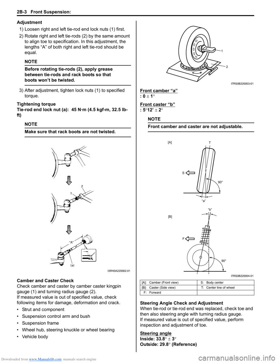
Adjustment1) Loosen right and left tie-rod end lock nuts (1) first.
2) Rotate right and left tie-rods (2) by the same amount to align toe to specification. In this adjustment, the
lengths “A” of both right and left tie-rod should be
equal.
NOTE
Before rotating tie-rods (2), apply grease
between tie-rods and rack boots so that
boots won’t be twisted.
3) After adjustment, tighten lock nuts (1) to specified torque.
Tightening torque
Tie-rod end lock nut (a): 45 N·m (4.5 kgf-m, 32.5 lb-
ft)
NOTE
Make sure that rack boots are not twisted.
Camber and Caster Check
Check camber and caster by camber caster kingpin
gauge (1) and turning radius gauge (2).
If measured value is out of specified value, check
following items for damage, deformation and crack.
• Strut and component
• Suspension control arm and bush
• Suspension frame
• Wheel hub, steering knuckle or wheel bearing
• Vehicle body Front camber “a”
: 0
± 1°
Front caster “b”
: 5 °12’ ± 2°
NOTE
Front camber and caster are not adjustable.
Steering Angle Check and Adjustment
When tie-rod or tie-rod end was replaced, check toe and
then also steering angle with turning radius gauge.
If measured value is out of specified value, perform
inspection and adjustment of toe.
Steering angle
Inside: 33.8 ° ± 3 °
Outside: 29.8 ° (Reference)
I3RH0A220002-01
[A]: Camber (Front view) S: Body center
[B]: Caster (Side view) T: Center line of wheel
F: Forward
2
1
I7RS0B220003-01
[B]
S T
90°
“a”
[A]
F
90°
“b”
I7RS0B220004-01
Page 445 of 1496
Downloaded from www.Manualslib.com manuals search engine Front Suspension: 2B-12
Front Wheel Hub, Disc, Nut and Bearing CheckS7RS0B2206008
• Inspect each wheel disc for dents, distortion and cracks.
A disc in badly damaged condition must be replaced.
• Check rust of installation face inside of wheel disc.
As rust affects adversely, remove it thoroughly.
• Check wheel nuts for tightness and, as necessary, retighten them to specification.
• Check wheel bolt press-fitted into wheel hub for wear, damage, poor thread condition, and looseness.
Replace defective bolt with a new one.
When bolt installation is found loose, replace both bolt
and wheel hub with new ones.
Tightening torque
Wheel nut: 85 N·m (8.5 kgf-m, 61.5 lb-ft)
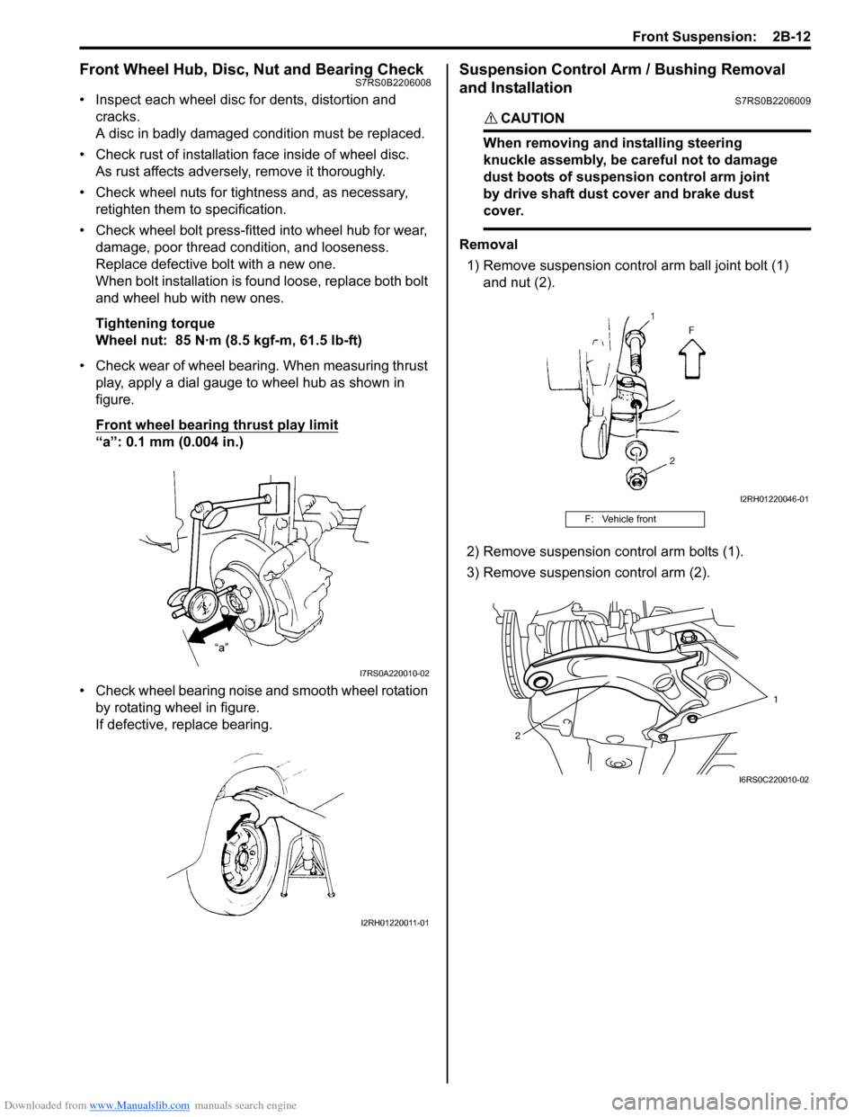
• Check wear of wheel bearing. When measuring thrust play, apply a dial gauge to wheel hub as shown in
figure.
Front wheel bearing thrust play limit
“a”: 0.1 mm (0.004 in.)
• Check wheel bearing noise and smooth wheel rotation by rotating wheel in figure.
If defective, replace bearing.
Suspension Control Arm / Bushing Removal
and Installation
S7RS0B2206009
CAUTION!
When removing and installing steering
knuckle assembly, be ca reful not to damage
dust boots of suspension control arm joint
by drive shaft dust cover and brake dust
cover.
Removal
1) Remove suspension contro l arm ball joint bolt (1)
and nut (2).
2) Remove suspension control arm bolts (1).
3) Remove suspension control arm (2).
I7RS0A220010-02
I2RH01220011-01
F: Vehicle front
I2RH01220046-01
1
2
I6RS0C220010-02
Page 453 of 1496
Downloaded from www.Manualslib.com manuals search engine Front Suspension: 2B-20
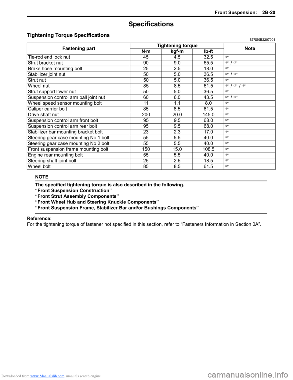
Specifications
Tightening Torque SpecificationsS7RS0B2207001
NOTE
The specified tightening torque is also described in the following.
“Front Suspension Construction”
“Front Strut Assembly Components”
“Front Wheel Hub and Steering Knuckle Components”
“Front Suspension Frame, Stabilizer Bar and/or Bushings Components”
Reference:
For the tightening torque of fastener not specified in this section, refer to “Fasteners Information in Section 0A”.
Fastening part
Tightening torque
Note
N ⋅mkgf-mlb-ft
Tie-rod end lock nut 454.5 32.5 �)
Strut bracket nut 909.0 65.5 �) / �)
Brake hose mounting bolt 252.5 18.0 �)
Stabilizer joint nut 505.0 36.5 �) / �)
Strut nut 505.0 36.5 �)
Wheel nut 858.5 61.5 �) / �) / �)
Strut support lower nut 505.0 36.5 �)
Suspension control arm ball joint nut 606.0 43.5 �) / �)
Wheel speed sensor mounting bolt 111.1 8.0 �)
Caliper carrier bolt 858.5 61.5 �)
Drive shaft nut 200 20.0 145.0�)
Suspension control arm front bolt 959.5 68.0 �)
Suspension control arm rear bolt 959.5 68.0 �)
Stabilizer bar mounting bracket bolt 232.3 17.0 �)
Steering gear case mounting No.1 bolt 555.5 40.0 �)
Steering gear case mounting No.2 bolt 555.5 40.0 �)
Front suspension frame mounting bolt 150 15.0 108.5�)
Engine rear mounting bolt 555.5 40.0 �)
Steering shaft joint bolt 252.5 18.5 �)
Wheel bolt 858.5 61.5 �)